Contents
i
About This Manual
Customer Information
Customer Response Card
Chapter 1. Getting Started
Vanguard 650 Series Features ...................................................................... 1-3
Sample Network Topology ........................................................................... 1-4
651/653 - Data Only ..................................................................................... 1-5
652/654 POTS Wit /Wit out Battery Backup ............................................. 1-6
652/654 Wit POTS Support ................................................................... 1-7
652/654 Wit POTs and Battery Backup ................................................. 1-8
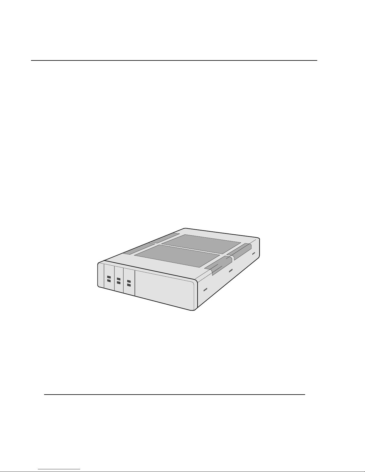
Hardware ...................................................................................................... 1-10
Detailed 650 Series Front Panel ................................................................... 1-11
Detailed 650 Series Rear Panel .................................................................... 1-13
Software ........................................................................................................ 1-14
Chapter 2. Installing 650 Series Hardware
C ecking Your S ipment Contents .............................................................. 2-2
C oosing a Site ............................................................................................. 2-3
Cabling t e 650 Series .................................................................................. 2-4
Powering Up t e Vanguard 650 Series ......................................................... 2-7
Removing t e Top Cover and Front Panel ................................................... 2-8
Chapter 3. Installing and Coldloading 650 Series Software
650 Operating Software and Option Images ................................................ 3-2
W ere to Get Operating Software ................................................................ 3-3
Installing Software ........................................................................................ 3-5
Coldloading 650 Series Operating Software ............................................ 3-6
Loading Software via TFTP Download ................................................... 3-8
Downloading Software Using t e Software Loader ................................ 3-10
Downloading Configuration Memory (CMEM) ...................................... 3-14
Vanguide Terminal ................................................................................... 3-16
Linking Software Images Using Software Builder .................................. 3-18
Selecting a Predesigned Configuration ........................................................ 3-19
Selecting a Predesigned Configurations Using t e CTP .......................... 3-20
Saving and Restoring Configurations Using Kermit ............................... 3-21
Saving and Restoring Configurations Using TFTP ................................. 3-23