VanLab Mercedes Sprinter 144 Assembly instructions

Fitting Guidelines
1

VANLAB FITTING GUIDELINES 2
Mercedes Sprinter 144”

Parts
VANLAB FITTING GUIDELINES 3
3x 2x4x
110x 8x 6x
2 holes 3 holes
Size #5 x 5/8” #6 x 3/8” #6 x ½” #8 x 1 ¼”
Quantity 616 4400
Use Part A12 Kitchen
Cupboard
Hinges
Magnet
Catches All Batten

Contents
The Rules & Process
The Sections
1. The Floor
2. Section A
3. Section B
4. Section C
5. The Table
VANLAB FITTING GUIDELINES 4

The Rules & Process
VANLAB FITTING GUIDELINES 5
IMPORTANT!
You MUST understand the Rules & Process before you begin,
as they need to be followed to assemble your kit correctly.
Refer back to them regularly during the build process.

The Rules
VANLAB FITTING GUIDELINES
The 4” Batten has 2 holes on one side and 1 hole on the
another
—
Always screw the 2 first (A)
—
Then the 3rd (B)
Batten Panel Symbols
The panels have symbols to show you the location of the batten and how to fix
the part. You have 3 symbols: The Rectangle, The Crosses and
A
B
Place the batten over the box on the
face you are looking at.
Screw into panel from the side you’re
looking at and screw through batten
first and into the panel
Place the batten on the opposite face
of the panel.
Screw from the side you’re looking at.
In this case, screw through the panel
first and into the batten
6
The 6” batten have 2 holes in the same orientation. They are
used for the Section B hatches only
—
The 8” batten have 3 holes. They are used for the rails (see
Page 19 & 24) only
The Rectangle
The Line
Place the batten over the box, on the
face you are looking at.
BUT, screw from the opposite side
The Crosses

VANLAB FITTING GUIDELINES 7
For anytime you see ‘The Rectangle’. Partially drive the screws
into the battens separately before fastening to the panel for
easier pilot hole location.
!Be careful to line up the pilot holes with the screw as the batten
may split if they are incorrectly aligned.
Don’t worry if you do, as we have provided plenty of spares!
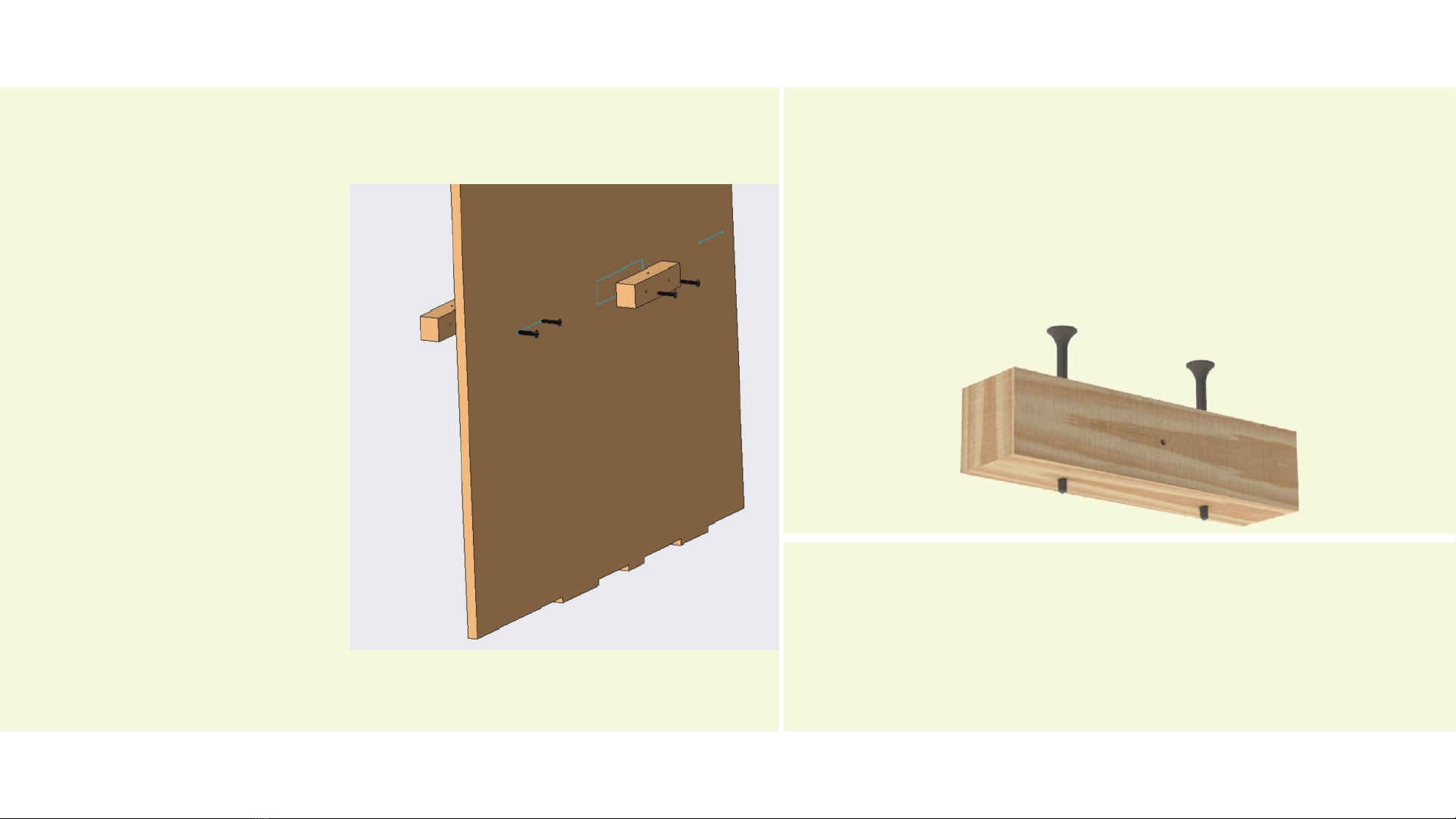
Key Tip!
Find Panel A3, as A3 has both ‘The
Rectangle’ and ‘The Line’ symbol
-The battens will be screwed in as
pictured..
-You can see that the rectangle
means the batten is on the front
face of the panel
-The line denotes that the block is
on the back side of the panel.
-Both are screwed in from the front
face of the panel
Let’s try an example:
For anytime you see ‘The Line’. Partially drive the screws
through the panel separately before fastening to the batten.
Same approach, but the opposite order.
Key Tip!

Adding panels to the floor
Batten on
panel
Fit panel Repeat
1
234
The Process
8
Key Tip!
Separate all the parts.
Stack the parts from section
A, section B and section C in
separate places before
building.
You’ll notice the panels are
engraved with a letter and a
number. Section A consists
of parts A1, A2, A3…..
Section B consists of parts
B1, B2, B3 etc.

VANLAB FITTING GUIDELINES 9
Section C
Section A
Section B
Side View
Section C
Section A
Section B
Plan View
The Sections
You’ll notice the panels are engraved with a letter and a number.
Section A consists of parts engraved A1, A2, A3… etc.
Section B consists of parts engraved B1, B2, B3… etc.
Section C consists of parts engraved C1, C2, C3… etc.

Lets get started!...
VANLAB FITTING GUIDELINES 1
0

1.The Floor
VANLAB FITTING GUIDELINES 1
1

VANLAB FITTING GUIDELINES 12

Lay the floor pieces down OUTSIDE the
Van first with the engravings facing up
Screw the batten to the floor
1
2
The Process
There are 5 floor sections.
1. Front left
2. Front middle
3. Front right
4. Middle section
5. Rear section
1
3
- You now need to screw each of the 20 batten to the
top face of the flooring sections. You can distinguish
what the top face of the floor is by the engraving. The
underneath face will be clear of any engravings.
-The batten locations are denoted by 2 ‘Crosses’ in a
rectangle (Reminder: see Page 6)
- To do this, place the batten down facing you BUT
screw from the otherside of the flooring so the screw
goes through the flooring FIRST and then into the
batten.
- Now the floor is in place outside the van you can screw
the batten to each part more easily before carrying
them inside the van and slotting in place like a jigsaw.
1
2
3
4
5

Screw the batten to the floor
2
The Process
1
4
- You now need to screw each of the 20 batten to the
top face of the flooring sections. You can distinguish
what the top face of the floor is by the engraving. The
underneath face will be clear of any engravings.
-The batten locations are denoted by 2 ‘Crosses’ in a
rectangle (Reminder: see Page 6)
- To do this, place the batten down on the top face you
BUT screw from the bottom face of the flooring so the
screw goes through the flooring FIRST and then into
the batten.
- Once all the batten is secured to the 5 flooring
sections, the flooring can be transferred to the van.
- It is slotted into place as per the previous page. It slots
in place like a jigsaw!
For the flooring, screw batten in from the bottom face

2. Section ‘A’
VANLAB FITTING GUIDELINES 1
5

Section A
VANLAB FITTING GUIDELINES
Find panel marked A1
1
Find the #8 x 1 ¼” screws and 4” batten
2
Fit all batten to panel A1. (refer back to
rules if unclear - Screw into panel first then
batten)
3
Slot A1 in place
(see marking on floor).
4
Secure A1 in place by fastening any
remaining pilot holes.
5
16

VANLAB
Find panel A2. Screw the batten on to A2 as per the symbol instructions.
Locate the A2 slot on floor and secure in place.
6
Repeat for A4.
8
Repeat for A3. Remember from our example earlier, A3 has batten on both
sides. Note the symbols on this part.
7
17
Section A

VANLAB FITTING GUIDELINES
Find Part A5.
-Screw all 4”batten into place as per the symbols.
-A5 also has 4 horizontal 8”battens.
-You will note the location as the line symbol is also 8”long. These 4
batten can be screwed in from the face as shown in the photo
-At this point, the two doors can be secured in place too. Using the
supplied small hinges and #6 x 3/8“screws,
-The doors can be secured into place from the front face of the panel.
9
18
Section A

VANLAB FITTING GUIDELINES
The shelves of A6, A7 and A8 can now be
fitted.
The Shelves rest on the batten of parts A2, A3
and A4 which you have already installed.
10 11
19
The shelves (A6, A7, A8) are screwed through the top to secure into place
Section A

VANLAB FITTING GUIDELINES
- You can now fit the rail A9.
- The grooves on rail A9 are used to locate the part on the front face of the kitchen
12
20
13 The rail is then secured with 4 holes through the front face using the existing pilot holes.
Section A
Table of contents
Popular Indoor Furnishing manuals by other brands

aspenhome
aspenhome I07-332-PEP/WBR Assembly instructions

IKEA
IKEA FREDEN instructions

Citta
Citta RADIAL FLOATING SHELF installation instructions

Balt
Balt Study Carrel 89789 Assembly instructions

Wilson & Fisher
Wilson & Fisher CHESAPEAKE BL15029 quick guide

BK RESOURCES
BK RESOURCES PTS-1848 Assembly instructions

rst brands
rst brands Vistano PS OP-PSCT2646-VST Assembly instructions

Welltime
Welltime LKZ 740372 Assembly instructions

LDI Spaces
LDI Spaces Safco Flaunt 3456 Assembly instructions

Furniture of America
Furniture of America CM7441Q Assembly instructions

BROSA
BROSA Prato Bedside Table Assembly guide

Manis-h
Manis-h 10850-1 Assembly instructions and directions for use