VANNER
VANNERVANNER
VANNER
Incorporated
Owners Manual
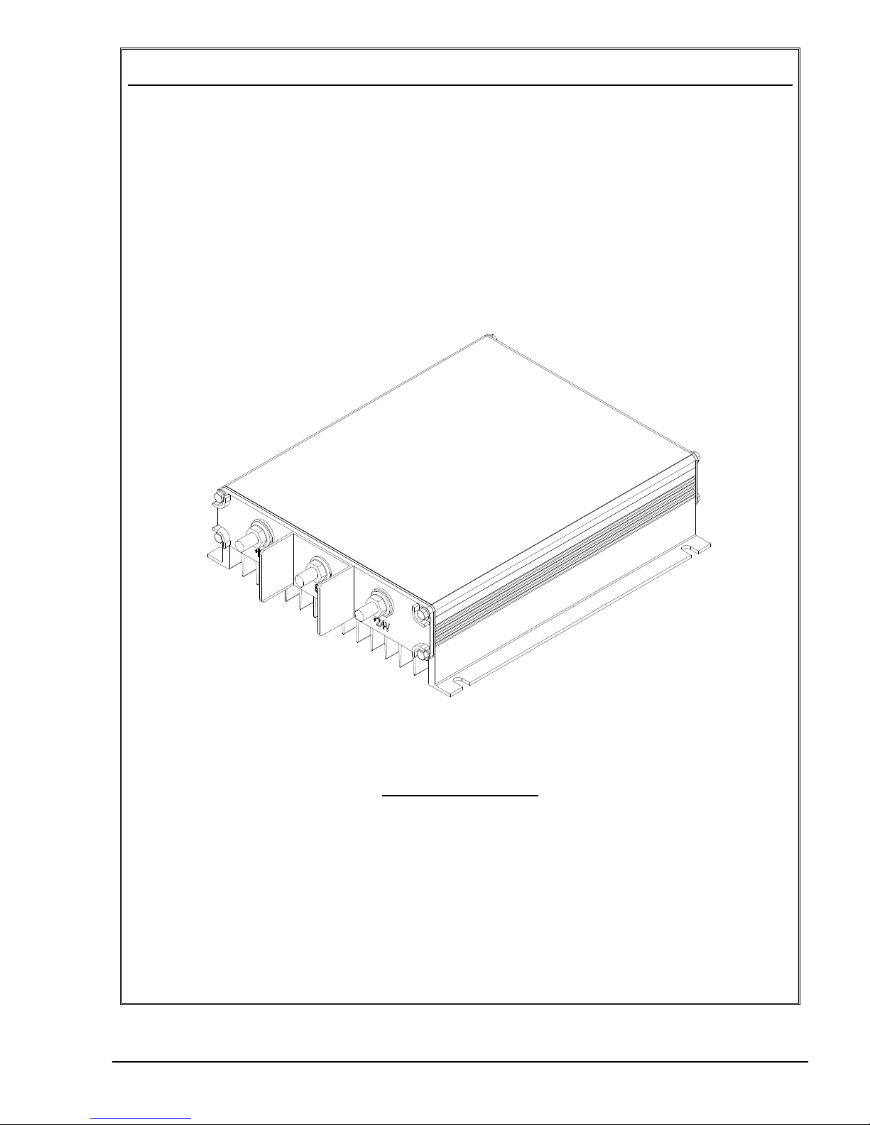
91-45 DC to DC Converter Owner’s Manual
3
Operation
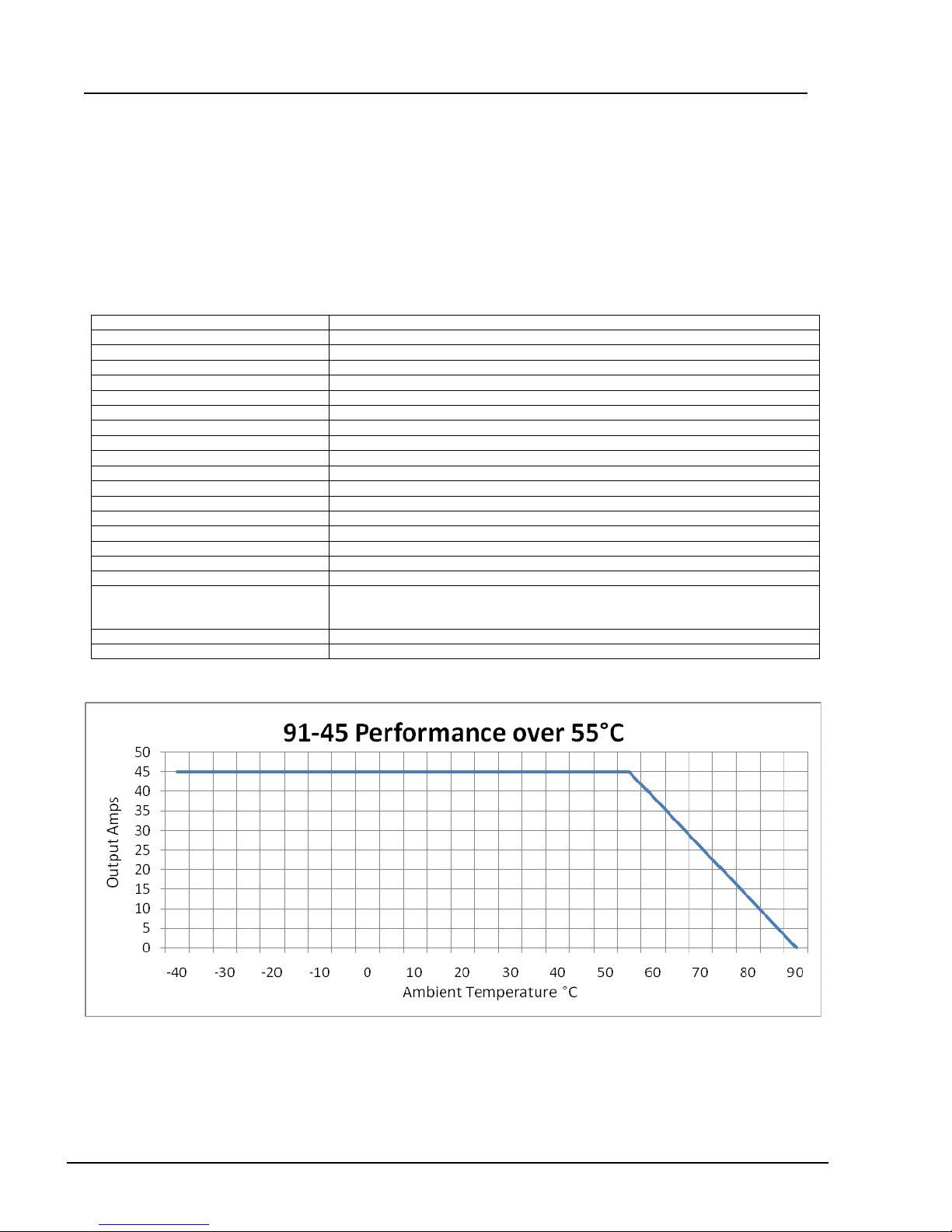
Normal Operation: Model 91-45 DC to DC Converter will provide up to 45 amps continuous output and
maintain 7.5 volts output voltage across the full range of DC input voltage. No minimum load is required.
No output condition: DC input voltage must be above 11 volts for the unit to “turn ON” and must remain
above 11 volts during operation.
ow output voltage due to overload: If the DC load tries to draw more than 45 amps the 91-45 will go into
“current limit”. “Current limit” reduces output voltage until output current does not exceed 45 amps. (For
example: output voltage would be 4.8V to a load that would draw 50 amps at 7.5V; 0.6V to a load that
would draw 60 amps at 7.5V; 15.5V to a load that would draw 80 amps at 7.5V).
“Current limit” cannot reduce output voltage BELOW input voltage. If the DC load is so great that output
voltage is reduced to (is the same as) input voltage, then the output current is no longer limited. Damage to
the 91-45 may result. Circuit protection at this point solely is provided by external fuses protecting the DC
input wiring and DC output wiring. (See wire and fuse sizing below recommending 100 amp minimum DC
input fuse and 50 amp maximum DC output fuse.)
Parallel Operation: Multiple Model 91-45 DC to DC Converters can be operated in parallel.
Installation Recommendations
Caution: This equipment employs components that tend to produce arcs and sparks. To prevent fire or
explosion, do not install in compartments containing batteries or flammable materials. Safety goggles should
always be worn when working near batteries
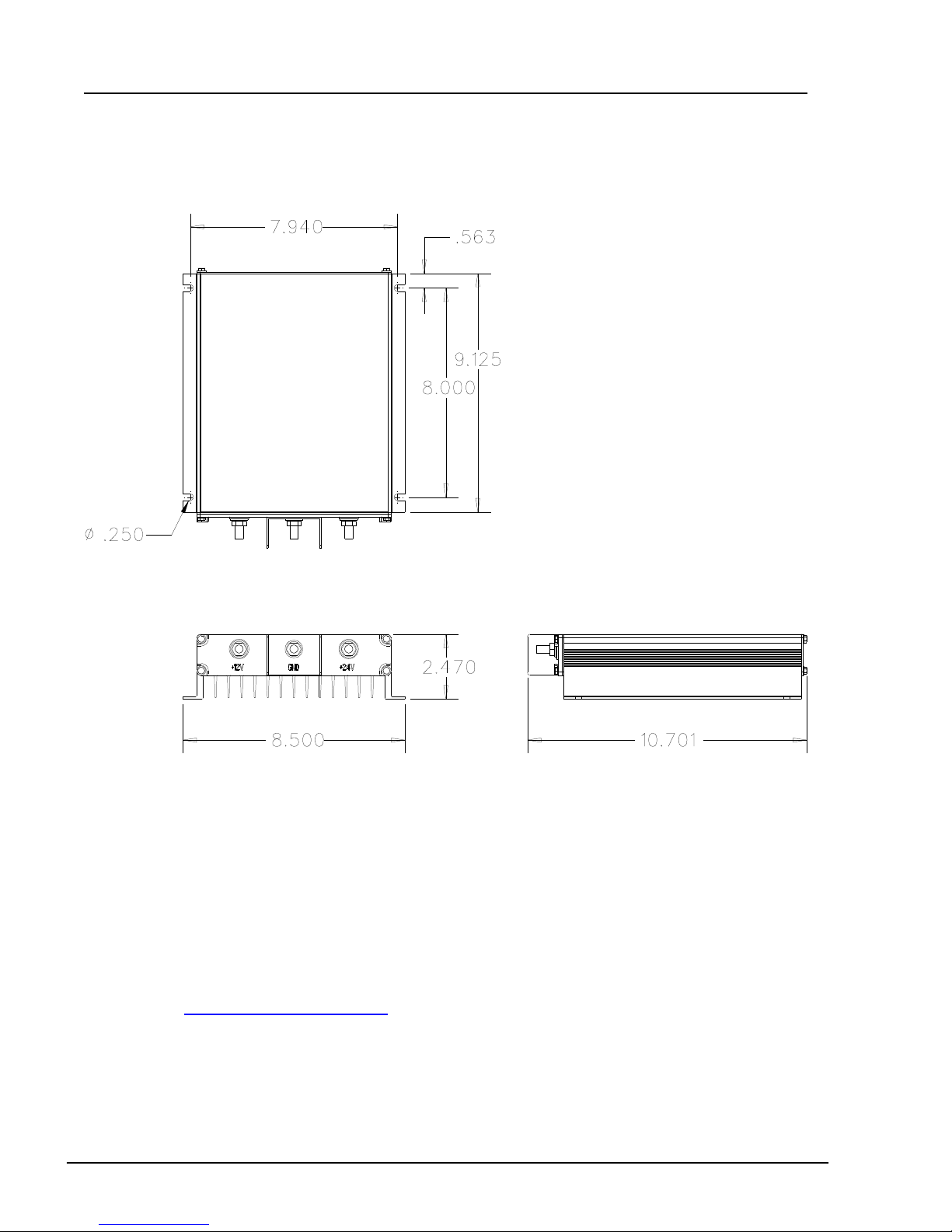
Terminal Connections: When connecting wires or cables to the electrical terminals (+ 4, GND, +1 ), do not
exceed the specified torque of 1 0 in-lbs. Torque values higher than specified may damage the product,
reducing performance or creating hazardous conditions.
Do not connect more than one conductor per terminal. Multiple wires and cables may overstress internal
components, resulting in poor performance or creating hazardous conditions.
Fusing: A fault protection device must be installed between the DC to DC Converter and the power source
(battery). A fault protection device would be any fuse or circuit breaker properly rated for the maximum DC
input current. This advisory is in accordance with SAE, NEC and UL, for mobile power applications.
Minimum Wire and Fuse Sizes: Connect Model 91-45 to the 1 vdc source using #6AWG or larger cable,
and protected by a 100 amp minimum fuse or circuit breaker. Use #6AWG cable for the 4V and GND with
50amp maximum fuse. Install adequate fuse protection to smaller wires feeding multiple output circuits.
Wire Temperature rating: Since the DC to DC Converter can be operated in temperatures up to 90ºC , use
wire rated at least 105ºC.
Mounting ocation: The DC to DC Converter may be mounted in any orientation, however, the
recommended orientation for optimum heat dissipation is wall mounted with fins vertical. It is recommended
that the wiring terminals be down to prevent the possibility of a falling metal object shorting the terminals. Do
not mount in zero-clearance compartment that may result in the DC to DC Converter overheating.
Environmental Protection: Do not expose to rain or moisture. The unit should be located in an area that will
protect it from direct exposure to moisture such as high pressure washing, rain, etc.