Vante 3800 User manual

Doc. No. 38000810-01 Rev. C
INSTRUCTION
MANUAL
3800 RF Generator and
3806MOD/3807MOD Handheld Sealing
Head

Vante® Model 3800/3806MOD/3807MOD
ii
This page intentionally left Blank

iii
Vante®
3480 E. Britannia Dr., Suite 120
Tucson, AZ 85706 USA
Telephone: (520) 881-6555
Fax: (520) 323-9055
Toll Free: (877) 565-5557
Doc. No. 38000810-01 Rev. C

iv
This page intentionally left blank

v
Introduction
Document Scope
Use this manual as a guide for the setup, adjustment and operation of the model 3800 RF
generator with the 3806MOD/3807MOD handheld sealing head. The information in this user
manual is based on technical data that has been verified and validated by Vante.
Intended Audience
This manual is intended for skilled personnel who understand the procedures for welding and
forming thermoplastic materials. Users assume any risks associated with setup and operation of
this product. Use model 3800 RF generator with 3806MOD/3807MOD sealing heads at your
own discretion.
Application
The 3800 RF generator supplies radio frequency (RF) energy to a peripheral device, such as a
3806MOD/3807MOD handheld sealing heads to perform the required operation. The Sealing
head welds tubing and film made of RF-reactive thermoplastic materials, including polyurethane
(PU), polyvinylchloride (PVC), ethylene vinyl acetate (EVA), certain types of nylons and certain
co-extrusions. Tubing may be filled with non-flammable liquid; however, the outside of the
tubing must always be clean and dry.
Exclusions and Limits of Liability
Vante makes no warranties, expressed or implied, and assumes no liability in connection with
any use of this information. Vante assumes no liability or obligation nor guarantees product
performance. The contents of this manual are not to be construed as license to operate under, nor
a recommendation to infringe upon, any patents.
Proprietary Information
All rights are reserved. Copying of the protected designs associated with the 3800 /
3806MOD/3807MOD system is strictly prohibited without the prior written consent of Vante.

vi
User Alerts
Throughout this document, WARNINGS, CAUTIONS, and NOTES notify the reader of
important and critical information.
WARNING: A warning indicates a condition or procedure that could cause bodily harm.
Warnings are enclosed in bold-line boxes.
CAUTION: A caution indicates a condition or procedure that could result in damage to the
unit. Cautions are enclosed in thin-line boxes.
NOTE: A note indicates important, useful information.
Safety symbols
Warning, hot surface
Warning, crush hazard
Warning, RF burns
Warning, risk of electric shock
Warning (general)
Protective Earth (PE)
Fuse
| On
O Off
CE Marking Information
For inquiries related to the CE marking of this product, please contact Vante at:
3480 E. Britannia Dr., Suite 120
Tucson, AZ 85706 USA
+1-520-881-6555 (tel)
+1-520-323-9055 (fax)

vii
Table of Contents
Introduction..................................................................................................................................... v
Document Scope......................................................................................................................... v
Intended Audience...................................................................................................................... v
Application.................................................................................................................................. v
Exclusions and Limits of Liability.............................................................................................. v
Proprietary Information .............................................................................................................. v
User Alerts................................................................................................................................. vi
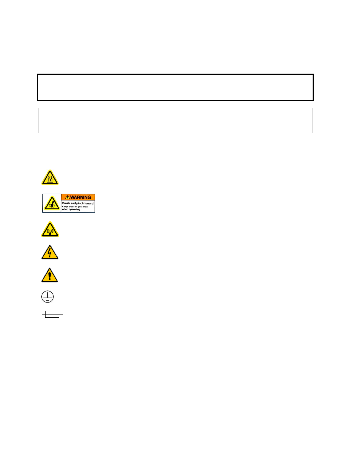
Safety symbols........................................................................................................................... vi
CE Marking Information ........................................................................................................... vi
List of Figures..............................................................................................................................viii
List of Tables ...............................................................................................................................viii
1. Description............................................................................................................................... 1
1.1. The RF Forming/Welding System ................................................................................... 1
1.2. Theory of Operation......................................................................................................... 1
1.3. Operator Safety ................................................................................................................ 1
1.4. Specifications................................................................................................................... 2
2. System Setup ........................................................................................................................... 3
2.1. Diagrams .......................................................................................................................... 3
2.2. Uncrating.......................................................................................................................... 4
2.3. Installation—3806MOD/3807MOD handheld sealer (Sealing Head)............................. 4
2.4. Power On.......................................................................................................................... 5
2.5. Generator Controls........................................................................................................... 6
3. System Operation .................................................................................................................... 7
3.1. Running a Cycle............................................................................................................... 7
3.2. Accessing the Internal Controller..................................................................................... 9
3.3. Programming the Internal Controller............................................................................... 9
3.4. Process Development..................................................................................................... 11
3.5. System Adjustments....................................................................................................... 11
4. Maintenance and Repair........................................................................................................ 13
4.1. Cleaning ......................................................................................................................... 13
4.2. Repair............................................................................................................................. 13
4.3. Returning a Unit for Service .......................................................................................... 13
4.4. Disposal of Equipment................................................................................................... 14
5. Radio Frequency System Safety Considerations................................................................... 15
5.1. Introduction.................................................................................................................... 15
5.2. RF Effects on Human Tissue ......................................................................................... 15
5.3. RF Effects on Pacemakers.............................................................................................. 15
5.4. Electrical Safety ............................................................................................................. 15
5.5. RF Effects on Electronic Equipment.............................................................................. 15
5.6. RF Effects in Potentially Explosive Atmospheres......................................................... 15
Index ............................................................................................................................................. 16

viii
List of Figures
Figure 2.1 3800 RF generator, front view....................................................................................... 3
Figure 2.2 3800 RF generator, rear view........................................................................................ 3
Figure 2.3 Fuse labels ..................................................................................................................... 4
Figure 2.5 Model 3806MOD/3807MOD midsize tube sealer........................................................ 5
Figure 2.6 LCD screen, idle state.................................................................................................... 5
Figure 3.1 Sealer operation............................................................................................................. 8
Figure 3.2 LCD screen, sealing state .............................................................................................. 8
Figure 3.3 LCD password entry screen........................................................................................... 9
Figure 3.4 LCD system configuration screen............................................................................... 10
List of Tables
Table 1.1 Specifications.................................................................................................................. 2

1
1. Description
1.1. The RF Forming/Welding System
The RF generator is the foundation of a sealing, forming, and/or welding system. The generator
supplies RF energy to a peripheral sealing head that is used to process RF-reactive thermoplastic
materials. The peripheral component of the system controls the generator.
Vante offers many off-the-shelf peripheral devices with diverse features that can be used for
most applications. Vante also offers engineering support for those who design their own custom
peripherals.
Custom peripherals must incorporate a matching network provided by Vante.
Vante will provide all of the components needed to support custom peripherals, such as
controllers, coaxial cables, interface cables, footswitches, matching network, forming/welding
heads, etc., at additional cost.
1.2. Theory of Operation
The 3800 / 3806MOD (3807MOD) System uses RF energy to seal, form, and weld certain types
of thermoplastic. The thermoplastic must be an RF-sensitive dielectric. The RF energy heats the
thermoplastic, allowing the material to change shape and bond, depending on the type of force
applied. When the material cools under the applied force, it retains its new shape or bond.
The 3800 RF generator produces RF power at a maximum of 200W. The frequency is controlled
by a solid state oscillator/amplifier operating at 40.68 ±0.020 MHz. The peripheral 3806MOD
(3807MOD) sealing head component applies force to a material throughout the heating and
cooling phases of the process.
The operator controls the dwell time and clamp time, so one system can process various
materials and tubing sizes.
1.3. Operator Safety
WARNING: Vante recommends strict adherence to the procedures specified in these user
manuals. Misuse or modification of an instrument may result in unsafe or
hazardous situations.
The 3800 / 3806MOD (3807MOD) forming system is designed to be used in a controlled
manufacturing environment by trained personnel. The 3800 / 3806MOD (3807MOD) system
applies RF equipment to form and weld thermoplastic tubing or parts.
Vante RF devices meet or exceed appropriate electric safety standards. These devices pose no
electrical shock hazard when used with properly fused and grounded outlets. Refer to section 5
for additional information on RF safety.
WARNING: This Vante product is designed for indoor use only.

2
WARNING: Do not use the peripheral sealing head to process tubing that contains flammable
liquid or hazardous materials.
1.4. Specifications Table 1.1 Specifications
Mechanical
Dimensions:
3800 generator
Width
Length
Height
Weight
17¾ in /43 cm
16 in / 41 cm
5 ¼ in / 13 cm
30 lb( 14 kg)
Dimensions:
Width
Length
Height
Weight
3806MOD Sealing Head
8.5 in / 21.6 cm
7.25 in / 18.4 cm
2 in / 5 cm
2.5 lb (1.1 kg)
3807MOD Sealing Head
10 in / 25.4 cm
7.75 in / 19.7 cm
2.5 in /6.4 cm
3.9 lb (1.8 kg)
Electrical
Power input
115 VAC, 6.3A, 50/60 Hz
230 VAC, 4A, 50/60 Hz
RF power output
Fixed: 150 –200W
Main AC power fuses
2 × 250 VAC, 5 × 20 mm T6.3A
2 × 250 VAC, 5 × 20 mm T 4A
Operating conditions
Temperature
8 –38°C
Humidity
90% relative humidity, non-condensing

3
2. System Setup
2.1. Diagrams
Figure 2.1 3800 RF generator, front view
Figure 2.2 3800 RF generator, rear panel
Star button aperture
should be plugged
DC button aperture
should be plugged
AC Power
Fuse Holder
Power SW
J2
J1
RF Output
External Air Input
Insert
Retract
AUX (Trigger/Arc)
LCD Screen
Green Button
Red Button

4
Figure 2.3 Fuse labels
WARNING: To avoid personal injuries or equipment damage use specified fuses only.
2.2. Uncrating
2.2.1. Remove the RF generator and peripheral components from their shipping
cartons. Inspect all components for damage. If any components are damaged,
contact Vante.
2.2.2. The serial plate indicates the model number and serial number of the unit.
Refer to the serial number when contacting Vante or one of its authorized
service centers.
2.2.3. Verify that the supplied power cable is compatible with your facility’s power
supply. Contact Vante if necessary to request a different power cable.
CAUTION: Do not connect the power cable to AC mains at this time.
CAUTION: Do not cover the top or side vents of the RF generator. Overheating can occur,
damaging the internal components.
WARNING: Do not insert or remove the AC power cord with the power switch in the ON
( ) position.
WARNING: User must provide means to isolate air supply. 60 –100 PSI max
WARNING: Keep fingers clear of the sealing head jaws—injuries can occur from crushing or
RF burns.
CAUTION: Severe damage to the sealing head electrodes occurs if fingers are introduced
between sealing head clamps.
2.3. Installation—3806MOD/3807MOD handheld sealer (Sealing Head)
2.3.1. 3800 / 3806MOD (3807MOD) System:
Verify power OFF the 3800 generator.
Connect the external airline, to the AIR IN port on the generator. See
figure 2.1.

5
Connect the air lines from the handheld sealer to the INSERT and
RETRACT ports on the generator. See Figure 2.1
2.3.2. Connect the coaxial cable from the sealing head to the BNC port (RF Output)
on the generator. See Figure 2.2.
2.3.3. Connect the 4-pin plastic connector on the control cable assembly from the
sealing head to the RF generator’s AUX port. See Figure 2.1.
Figure 2.5 Model 3806MOD (3807MOD is the large size version) midsize tube sealer
2.4. Power On
2.4.1. Switch the power switch to ON ( ). See Figure 2.2
2.4.2. The LCD screen and the exhaust fan activate.
NOTE: Transistor electronics allow the RF generator to start operating as soon as it is
powered on; there is no warm-up period.
If the generator fails to power on, refer to section 4.2.
2.4.3. The LCD screen displays the device name, model number, and software
version. After a short delay, the system enters an idle state. The LCD screen
says “Ready.” See Figure 2.6.
Figure 2.6 LCD screen, idle state
NOTE: If the LCD screen says, “Not Ready,” the generator cannot be triggered.

6
2.5. Generator Controls
2.5.1. The internal controller is programmed to control the RF energy intervals and
sequence.
2.5.2. The green and red buttons are used to adjust program parameters.
2.5.3. The generator is activated by the activation switch on the peripheral device.

7
3. System Operation
3.1. Running a Cycle
WARNING: Keep fingers and other objects clear of the electrodes and the coaxial connector in
the peripheral sealing head when processing materials. Severe burns, RF injuries,
and/or crush injuries may occur. Do not use this system to seal tubing that
contains flammable or other hazardous materials.
CAUTION: Improper use can severely damage the generator and/or sealing head.
Always keep fingers and other objects clear of the electrodes in the sealing head
to avoid injuries and damaging the electrodes.
Never squeeze the trigger without tubing between the jaws. Damage to the sealing
jaws and poor sealer operation can result.
3.1.1. Ensure that the 3800 generator is in an idle state. The LCD screen says
“Ready.” See Figure 2.6
3.1.2. Ensure that the materials being processed are clean and dry.
3.1.3. Position the materials in the sealer jaws as shown in Figure 3.1. The tube
positioner is a visual indicator which helps the operator create consecutive
seals with consistent spacing between them. The knob of the tube positioner
can be loosened so the positioner can be easily adjusted by the end-user to a
desired distance from the sealing region. Then, after the first seal is
completed, the operator can visually line the center of that seal up with the
radius on the end of the tube positioner. This will set the tube in a position for
the next seal to be conducted at the specified distance from the first seal. The
range the tube positioner can be set from is 1.75” to 2.5” between seals.

8
Figure 3.1 Sealer operation
3.1.4. Pull the trigger on the handheld sealing head.
The LCD says “Sealing.” See Figure 3.2.
Figure 3.2 LCD screen, sealing state
3.1.5. Continue holding the trigger until the sealing cycle is complete.
NOTE: Four conditions can terminate a cycle before it is complete:
Releasing the trigger on the handheld sealing head.
Pressing the red button on the generator.
Loss of the ready signal.
Automatic detection of an arc (a message displays on the LCD screen).

9
If the cycle is interrupted, RF energy is cut off, but the sealing head remains
closed for the duration of the post delay time.
WARNING: Allow the material to cool before proceeding.
3.1.6. Once the cycle ends, the generator returns to an idle state.
NOTE: When spacing seals, make sure that the distance between seals is at least 10 times
the diameter of the tubing. Seals that are too close together can cause segments
to rupture.
3.2. Accessing the Internal Controller
3.2.1. Ensure that the generator is in an idle state. The LCD screen says “Ready.”
See Figure 2.6.
3.2.2. Press the green button and red button at the same time until the LCD screen
changes to the password entry screen. See Figure 3.3.
Figure 3.3 LCD password entry screen
The password is a 4-digit numeric code. One digit is active at a time; the
remaining three are masked with * characters.
3.2.3. Press the green button to increment the active digit. Press the red button to
decrement the active digit.
3.2.4. Press and hold the green button to activate the next digit (to the right). Press
and hold the red button to activate the previous digit (to the left).
3.2.5. Press and hold the green button and the red button at the same time to submit
the password.
If the entered password is correct, the LCD screen shows the system
configuration screen.
If the entered password is incorrect, the generator returns to an idle state.
NOTE: The default password is 0000. To change the password, refer to section 3.5.2.
3.3. Programming the Internal Controller
3.3.1. After a valid password is entered, the LCD screen shows the system
configuration screen. See Figure 3.4.

10
Figure 3.4 LCD system configuration screen
3.3.2. The following parameters are programmable:
Pre-delay: number of seconds after a cycle is triggered, before RF energy
is activated. The maximum setting is 2.
NOTE: The sealing head closes during the pre-delay.
EOS-delay: number of seconds RF energy is activated. The maximum
setting is 5.
Post-delay: number of seconds after RF energy is deactivated, before the
material is released. The maximum setting is 5.
NOTE: The material cools during the post-delay. Releasing the material too soon can
affect the seal quality.
Clear counters: reset the arc and cycle counters to zero. See 3.5.1.
Change password: set a new password. See 3.5.2.
NOTE: The arc and cycle counters remain visible during programming.
3.3.3. To adjust the value of the pre-delay, EOS-delay, or post-delay, use the green
button to increment the value or the red button to decrement the value.
3.3.4. Press and hold the green button to change to the next parameter. Press and
hold the red button to change to the previous parameter.
3.3.5. Press and hold the green button and the red button at the same time to enter
the new values and return the generator to an idle state.

11
3.4. Process Development
WARNING: Keep fingers and other objects clear of the electrodes in the peripheral when
processing materials. Do not touch the coaxial connector connected to the sealing
head when RF energy is being applied. Severe burns, RF injuries, and/or crush
injuries may occur.
Do not use this system to seal tubing that contains flammable or other hazardous
materials.
CAUTION: Improper use can severely damage the generator and/or sealing head.
Always keep fingers and other objects clear of the electrodes in the
forming/welding head to avoid damaging the electrodes.
NOTE: Vante may recommend process settings for computer and manual controls;
however, users are responsible for determining the control settings that work best
for their application(s).
3.4.1. Run an initial sealing cycle to establish baseline results.
3.4.2. Use the internal controller (see section 3.3) to adjust the RF timing.
3.4.3. Run a second cycle to determine how the settings changes affect the seal
quality.
3.4.4. Continue to check and adjust until the settings produce the desired results.
3.5. System Adjustments
3.5.1. To reset the arc and cycle counters, navigate to the configuration screen (see
3.2).
Cycle through the process parameters (pre-delay, EOS delay, and post delay)
until the LCD displays “CLEAR COUNTERS.”
Use the red and green buttons to select YES.
Press and hold both the green and red buttons to finish.
NOTE: Clearing the counters resets both the arc and cycle counters to zero. There is no
way to recover this information after it is cleared.
3.5.2. To change the password, navigate to the configuration screen (see 3.2 ).
Cycle through the process parameters (pre-delay, EOS delay, post delay, and
clear counters) until the LCD displays “CHANGE PASSWORD.”
Use the red and green buttons to select YES. Press and hold the green button.
The LCD screen changes to the password entry screen. See Figure 3.3.

12
The password is a 4-digit numeric code. One digit is active at a time; the
remaining three are masked with * characters.
Press the green button to increment the active digit. Press the red button to
decrement the active digit.
Press and hold the green button to activate the next digit (to the right). Press
and hold the red button to activate the previous digit (to the left).
Press and hold the green button and the red button at the same time to submit
the new password.
This manual suits for next models
2
Table of contents
Other Vante Food Saver manuals