Vanteon vProtean User manual

Vanteon ♦99 Garnsey Road, Suite 200 ♦Pittsford, NY ♦14534 ♦585.419.9555
www.vanteon.com
User Manual
Version 3.1
vProtean™ Software Defined Radio

User Manual –vProtean Software Defined Radio
Information in this document is subject to change without notice
August 15, 2022 Vanteon Proprietary and Confidential i
Contents
1Introduction...................................................................................................................... 1
2Proper Care and Handling .................................................................................................. 1
3Technical Overview ........................................................................................................... 1
3.1 Block Diagram ............................................................................................................ 1
3.2 High Level Specifications ............................................................................................. 2
4Hardware Interfaces.......................................................................................................... 2
4.1 Connectors ................................................................................................................. 3
4.1.1 J2 Connector ........................................................................................................ 3
4.1.2 J14 Connector ...................................................................................................... 7
4.2 Switches..................................................................................................................... 7
4.3 LEDs ........................................................................................................................... 7
4.4 Mounts ...................................................................................................................... 7
5Software versions and Support HW.................................................................................... 8
6User Console..................................................................................................................... 8
6.1 UART.......................................................................................................................... 8
6.2 Main Menu................................................................................................................. 8
6.2.1 TX1/RX1 and TX2/RX2 Settings Menu.................................................................... 9
6.2.2 TX1 and TX2 Waveform Select Menu..................................................................... 9
6.2.3 TX1 and TX2 File Select Menu ............................................................................... 9
6.2.4 RX Waveform Capture Settings Menu ................................................................. 10
7Customer Support ........................................................................................................... 10
8Terms and Conditions of Sale........................................................................................... 10
9One Year Warranty.......................................................................................................... 11
10 Copyright Notice ............................................................................................................. 11
11 Trademark Acknowledgement ......................................................................................... 11

User Manual –vProtean Software Defined Radio
Information in this document is subject to change without notice
August 15, 2022 Vanteon Proprietary and Confidential 1
1Introduction
The Vanteon vProtean™ is a 2x2 software defined radio (SDR) that targets communications, signal
intelligence, and other multi-band processing applications. It is based on the Analog Devices ADRV9004
highly integrated wideband RF transceiver and the Xilinx Zynq-7020 all programmable System-on-Chip
(SoC). The vProtean SDR has a custom RF front end that is highly flexible, allowing its frequency range to
be configured from 30 to 6000 MHz.
Each vProtean SDR is pre-loaded with the vProtean SDR Evaluation Kit (VPROKIT-21) firmware. The
VPROKIT-21 firmware includes Vanteon proprietary, programmable logic cores and executable code to
perform transmit and receive functions via a menu-based UI over USB enabled com port from a host
computer (host not included). An encrypted Vivado Project of the VPROKIT-21’s FPGA firmware, along
with source code of the User Interface (UI) firmware is available under a free license agreement. The
vProtean schematic and layout design files, and Vanteon-proprietary DSP cores are available with a paid
license. Contact Vanteon Sales for more information.
2Proper Care and Handling
All Vanteon products are thoroughly tested before shipment. The vProtean SDR is guaranteed to be
functional at the time it is received by the customer. Improper use or handling of the vProtean SDR can
easily cause the device to become non-functional. Listed below are some examples of actions which can
prevent damage to the unit:
1. Never allow metal objects to touch the circuit board while powered.
2. Always properly terminate the transmit port with an antenna or 50Ω load.
3. Always handle the board with proper anti-static methods.
4. Never allow the board to directly or indirectly come into contact with any voltage spikes.
5. Never allow any water, or condensing moisture, to come into contact with the boards.
6. Never apply more than 0 dBm of power into any RF input.
7. Always use at least 30dB attenuation if operating in a loopback configuration.
The vProtean SDR is sold for evaluation purposes and test equipment. If you choose to use your vProtean
and Carrier to transmit using an antenna, it is your responsibility to make sure that you are in compliance
with all laws for the country, frequency, and power levels in which the device is used. Additionally, some
countries regulate reception in certain frequency bands. Again, it is the responsibility of the user to
maintain compliance with all local laws and regulations.
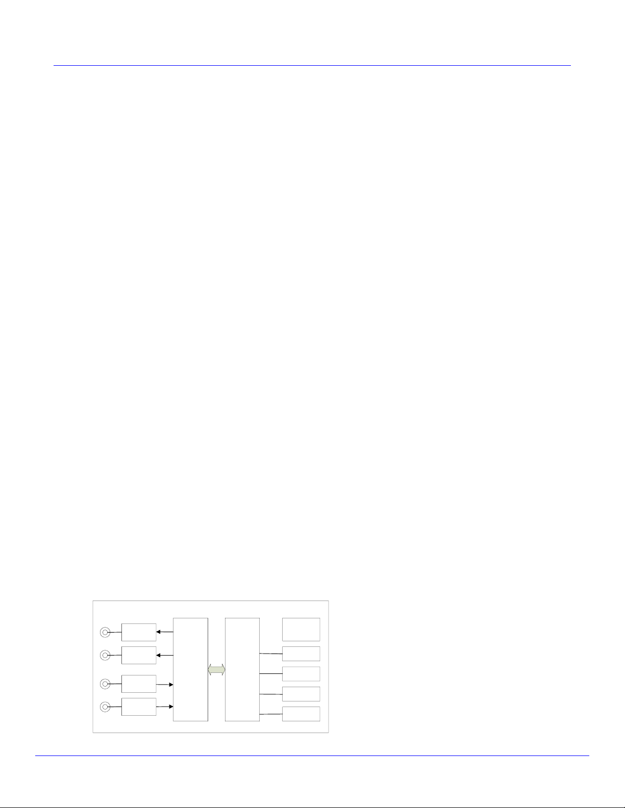
3Technical Overview
3.1 Block Diagram
vProtean SDR
Xilinx
Zynq
7020
Power
Flash
Debug I/F
(SPI, UART)
DDR
Host I/F
USB/ENET
ADRV9004
HMC8411
HMC8411
PHA-1H+
PHA-1H+

User Manual –vProtean Software Defined Radio
Information in this document is subject to change without notice
August 15, 2022 Vanteon Proprietary and Confidential 2
3.2 High Level Specifications
Frequency Band 1
30 to 6000 MHz
Instantaneous Bandwidth
12 kHz to 40 MHz
Number of transmitters
2
Number of receivers
2
Output Transmit Power
Variable up to 19 dBm
Dimensions
9.0 cm x 4.2 cm
Host interface
UART, USB, Ethernet, I2C and SD Card
Antenna connections
MMCX RF connectors
Power control
Wide range of output power from –20 dBm to +19 dBm
Flash
512 Mb
DDR SDRAM
4 Gb
Input Voltage
2.0 VDC to 3.6 VDC
Front End Module Voltage
3.3 VDC to 4.5 VDC
4Hardware Interfaces
Figure 1: vProtean RevC, Top View

User Manual –vProtean Software Defined Radio
Information in this document is subject to change without notice
August 15, 2022 Vanteon Proprietary and Confidential 3
Figure 2: vProtean RevC, Bottom View
4.1 Connectors
The vProtean SDR has a number of connectors that allow it to be interfaced to a host carrier board, and
connectors for antennas. That table below lists all of the connectors and their associated functions. Refer
to Figure 1 and Figure 2 for connector locations
Connector
Type
Function
J2
2x50 100 pin header
JTAG, UART, Boot Mode, Power, Reset, USB, Ethernet,
SD Card, I2C, GPIO
J3
MMCX
Transmit 1
J4
MMCX
Monitor 1 (DPD models only)
J5
MMCX
Receive 1
J7
MMCX
Transmit 2
J8
MMCX
Monitor2 (DPD models only)
J9
MMCX
Receive 2
J10
MICTOR
Debug
J11
MMCX
External Clock
J12
SMP
External LO1 (not fitted)
J13
SMP
External LO2 (not fitted)
J14
2-pin PicoBlade header
Fan Connector
4.1.1 J2 Connector
The J2 connector is a 100 pin header which may be used as an interface to a host carrier board, such as
the Vanteon Carrier board. The connector provides signals for several peripheral interfaces including
JTAG, UART, USB, Ethernet, SD Card, I2C and GPIO. Unless otherwise noted, minimum voltage for all
signals is PCB ground.
Other manuals for vProtean
1
Table of contents