Vari F-530.1 User manual

Mulcher
F-530.1
Instructions for use
2003

F-530.1
2
Contents
1 Basic information ...............................................................................................................3
2 Introduction ........................................................................................................................4
2.1 Warning ......................................................................................................................4
3 Operation safety..................................................................................................................5
3.1 Safety regulations .......................................................................................................5
3.2 Safety pictographs ......................................................................................................6
3.3 aximum values of noise and vibrations as measured by AO-206 SZZPLS Prague 7
4 Use, technical specification and technical description of the machine ..............................7
4.1 Use of the machine .....................................................................................................7
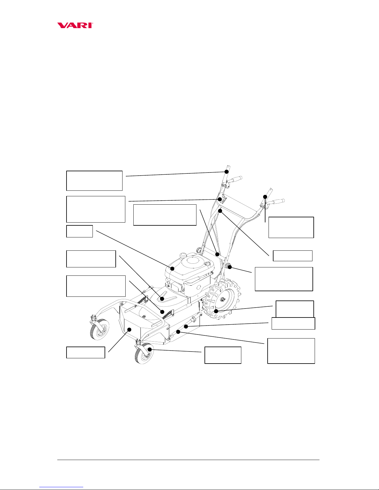
4.2 Technical description of the machine.........................................................................8
5 Instructions for use .............................................................................................................9
5.1 achine assembly ......................................................................................................9
5.2 Putting into operation ...............................................................................................10
5.3 Starting the mowing knife ........................................................................................11
5.4 achine travel ..........................................................................................................11
5.5 achine stop.............................................................................................................13
5.6 Working with the machine........................................................................................13
5.6.1 Adjusting the mowing height ...........................................................................13
5.6.2 owing of grass stands ....................................................................................14
5.6.3 Arrestment of guide wheel suspensions ...........................................................15
5.7 achine accessories .................................................................................................15
5.7.1 Slide shoe and its assembly ..............................................................................15
5.7.2 Swinging and mixing knife complement..........................................................16
6 aintenance, care and storage..........................................................................................16
6.1 Lubrication................................................................................................................16
6.1.1 Gear oil replacement and refilling....................................................................16
6.1.2 Engine oil replacement .....................................................................................18
6.1.3 Table of machine lubrication............................................................................18
6.2 Tightening of bolted connections .............................................................................19
6.3 Replacement and sharpening of working knife ........................................................19
6.4 V-belt replacement and adjustment of tension pulley ..............................................21
6.5 Setting-up litz wires of pulley, brake and machine travel gear clutch......................22
6.6 Diagnostics of driving problems...............................................................................23
6.7 Tyres of driving wheels ............................................................................................23
6.8 Table of service operations.......................................................................................24
6.9 Washing and cleaning of the machine......................................................................24
6.10 Storage......................................................................................................................25
6.11 Liquidation of packaging and machine after service life expiration ........................25
7 Instructions for ordering spare parts.................................................................................26
8 Contact to manufacturer ...................................................................................................26
9 List of components ...........................................................................................................26
9.1 Knife casing and guide wheels .................................................................................27
9.2 owing knife drive ..................................................................................................29
9.3 Handlebars................................................................................................................31
9.4 Wheel drive gear.......................................................................................................33
9.5 Gearbox.....................................................................................................................35
9.6 Swinging and mixing knives, slide shoe ..................................................................37
10 Letter of guarantee............................................................................................................39

F-530.1
3
1 Basic information
Ask your dealer to provide unpackaging of the machine and briefing.
Fill in the following table with data on your machine. The data are important for ordering
spare parts.
It is advisable to have a copy of this page with all data on the machine purchase for the
case of loss or theft of the original record.
Type F-530.1
Engine type*) riggs&Stratton INTEK EDGE 60 OHV
riggs&Stratton INTEK PRO 65
achine serial number
Engine serial number
Date of delivery (sale)
Supplier
Address
Telephone/Fax
*) Delete where inapplicable
Notes:
The product’s design complies with the requirements of Act No. 22/1997 Gaz. and
with all relating legislation, decrees, regulations, directives and norms.
anufacturer reserves the right of technical modifications and machine innovations
which do not impact the machine function and safety.

F-530.1
4
2 Introduction
Dear customer,
Thank you for trusting our products. You have become owner of one machine from a
wide range of machines and attachments made by VARI, a.s. as a system of gardening,
farming, small agricultural and communal technology.
Please read the Instructions for use carefully. If you follow them properly, you will get
our products performing a reliable work for years.
2.1 Warning
User is obliged to get acquainted with the Instructions for use and to follow all
instructions for machine operation so that the user’s and other persons’ health and property
do not suffer any harm.
Safety instructions contained in this manual do not describe all situations or conditions
possibly occurring in practical use. Safety factors such as common sense, diligence and
scrupulousness are not included; it is assumed, however, that all persons authorized for
machine operation or maintenance do possess the intelligence.
The machine can be operated only by persons in good mental and physical condition. For
the professional use of the machine the machine owner is obliged to ensure a work safety
training and provide instructions on machine control for operators and to keep records on
these trainings and briefings.
Should some instructions in the manual be intelligible, you are encouraged to contact
your dealer or directly the manufacturer of the machine. The contact address and
telephone/fax connection are to be found at the end of the manual.
Instructions for use supplied with the machine are an integral part of the machine. They
have to be available at any time, placed at an accessible place with no risk of their damage. In
the case that the machine is sold to another person, the Instructions for use must be given to
the new machine owner. If the above conditions are not met, the manufacturer bears no
responsibility for incurred risks, accidents and injuries resulting from the machine operation.
The manufacturer bears no responsibility for damages caused by unauthorized and
incorrect use of the machine and for damages caused by any machine modifications not
authorized by the manufacturer.
To prevent injuries of operators and other people occurring in the vicinity of the machine,
it is absolutely crucial to follow safety regulations marked in the Instructions for use with the
following warning safety symbol:
If you see the symbol in the manual, read the
attached instructions cerefully !

F-530.1
5
3 Operation safety
3.1 Safety regulations
This international symbol indicates important messages concerning safety. When you see
the symbol, be aware of a possible injury to yourself or to other persons and read attached
instructions carefully.
The machine operator must be over 18 years of age. He (she) must be made familiar with
the instructions for use of the machine and is supposed to be informed of general
principles of work safety.
Prior to carrying out any activities in the near vicinity of the machine, switch the engine
off and wait until the mowing knife stops moving! Before leaving the machine alone,
switch off the engine!
Never let the engine running at maximum speed or idling for a long time with the
mowing knife drive clutch and travel wheel drive clutch being switched off! Components
of the machine drive (V-belt, belt pulley, clutch pulley, etc.) might be damaged!
Prior to each employment of the machine, check its parts (working mechanism or its
casing in particular) for possible damage or loosening. Possible defects must be rectified
without delay. Repairs are to be made only with original spare parts.
Before using the machine, the stand must be cleared of solid bodies such as stones, wires,
construction debris, etc., which could be flinging up or which might damage the machine.
If these cannot be removed, don’t work the places.
The machine is equipped with the rotating working knife. aximum circumferential
speed is 109 m.sec-1. Therefore, see to it that other persons move at a safe distance from
the machine when it is in operation with regard to a possibility of mown stand or solid
objects flying away!
achine operators should use working aids authorized to CSN EN 166 or CSN EN 1731
(tight-fitting garments, sturdy shoes, working gloves and protection glasses). Keep a safe
distance given by the handle.
Don’t start the engine in enclosed spaces! Pay an increased attention when handling the
machine since the exhaust silencer remains hot after the engine has been switched off;
make sure that there are no leakages and spills on engine parts when refuelling. If they
happen to occur, dry out the stained parts or wait until the petrol evaporates.
When the machine is in operation, all other persons (children in particular) and animals
have to be outside the machine’s working space. The machine operator can continue
working only after they have been shown out to a safe distance.
Removal of any protective equipment and machine casings is forbidden.
Safe slope accessibility of the machine is 10°. aximum inclination of engine at work is
20° for a longer time and 30° for a shorter time (up to 1 minute).
All kinds of machine repair, adjustment, lubrication and cleaning are to be made with the
machine switched off and spark plug cable disconnected.

F-530.1
6
3.2 Safety pictographs
The user is obliged to keep pictographs on the machine legible and to provide for their
replacement in the case of their damage. There are following labels with safety pictographs
on the machine:
Self-stickers located on the knife casing:
1. 2. 3. 4.
1. Instructions for use to be thoroughly studied prior to machine use.
2. During the machine maintenance, the conductor should be disconnected from the spark
plug.
3. Putting one’s hands or feet into the mowing knife working space is prohibited – danger of
injury.
4. Keep a safe distance from the machine in operation – danger of injury by flying material
fragments and objects.
Self-sticker located on the plate behind the engine:
1. Instructions for use to be thoroughly studied prior to machine use.
2. During the machine maintenance, the conductor should be disconnected from the spark
plug.
3. No entry of exposed and other persons into the working space of the machine.
4. Putting one’s hands or feet into the V-belt space is prohibited .
5. Keep the maximum permitted-safe slope accessibility of the machine at work.
R
Arrow for the mowing knife
direction of rotation

F-530.1
7
Self-sticker on the machine travel switch Self-sticker for switching on the mowing
is located near the control lever on the left knife drive is located near the control
handlebar grip. lever on the right handlebar grip.
The machine is still. The knife is still.
The machine travels. The knife turns.
3.3 Maximum values of noise and vibrations as measured by AO
206 SZZPLS Prague
Level of acoustic pressure at operator’s site LpAeq,T = 87 d (according to NV No. 194/2000
Gaz.).
Level of acoustic performance of the machine LWA = 100 d (according to NV No. 9/2002
Gaz.).
Weighted effective value of accelerated vibrations transmitted onto the operator’s hands
(vector sum of rectilinear vibrations on individual axes) is 6.3 m.sec-2 (testing method to
CSN EN 1033).
4 Use, technica specification and technica description of
the machine
4.1 Use of the machine
The mulcher is meant for mowing grass stands of all kinds of stalky grasses, preferrably
old and dry, on both maintained and unkept sites.
The period most suited for the machine use is outside the growing season, i.e. in the
months of arch, at the beginning of April and in the period from the end of August to
November. In these periods the stands are usually dry and the mowing knives are capable of
crushing them into small pieces which need not be removed from the surface. The
recommended height for cutting newly grown up stands is up to 40 cm.
Engagement width has to be always accommodated to the density of the mown
stand.
The machine can also be used as a mower for park treatment of grass stands with no high
demands for grass stubble quality (flat terrain, low cut, ruts after machine wheels, etc.)

F-530.1
8
4.2 Technical specification
F-530.1 Unit Value
Length mm 1150
Width mm 610
Height mm 1050
Weight kg 80
ax. engagement width cm 52
Working knife speed (according to max. engine rotations) RP 3200-3600
Circumferential speed of knives (according to max.
engine rotations)
m.sec-1 99-109
Travel speed (according to max. engine rotations) km.hr-1 2.2-2.4
Area performance (according to stand type) m2/hr 800-1400
Gear-box oil filling litres 0.15
Oil grade API GL-4, GL-5
SAE 90, 80W-90
Engine Unit Value
Type - B & S INTEK EDGE 60 OHV
Cylinder volume cm3 189
Drilling x lift mm 68.3 x 51.8
ax. k/RP N.m/RP 10.9/2500
ax. engine speed RP 3200
Tank capacity litres 1.5
Petrol (leadless) oct.no. 91-95
Oil filling litres 0.65
Oil SAE 15W-40
Spark plug - CHA PION RC12YC
- BRISK DR17YC
Type - B & S INTEK PRO 65 OHV
Cylinder volume cm3 189
Drilling x lift mm 68.3 x 51.8
ax. k/RP N.m/RP 10.9/2500
ax. engine speed RP 3600
Tank capacity litres 1.5
Petrol (leadless) oct.no. 91-95
Oil filling litres 0.77
Oil SAE 15W-40
Spark plug - CHA PIONRC12YC
- BRISK DR17YC
4.2 Technical description of the machine
The machine is based on a rigid frame in which a gear-box is placed with primary worm
gear for machine travel and with claw clutch to be switched on after pressing the machine
travel lever. The secondary gearing onto the axis of wheels is designed as a roller chain. The
wheels have treads with the tractor herringbone pattern which finds employment especially in
sloping terrains. The wheels are equipped with the ball free wheel for easier turning and
machine handling.
Guide wheels with a possibility of mowing height adjustment and side arrestment are
attached to the knife casing which is equipped with a removable front part to be
automatically elevated when the machine enters a dense grass stand.

F-530.1
9
On the upper part of the frame there is a 4-stroke combustion engine to prime the machine
travel gear through the pin clutch and through the V-belt the mowing knife which is installed
on the knife shaft through the friction clutch. The knife is made of high-quality hardened
steel. The mowing knife drive is to be switched on by the pulley-controlled lever on the
handlebars. A part of the mowing knife is also a safety brake to stop the mowing knives after
the mowing knife drive clutch lever has been released.
The knife with bent ends and blade is installed on the knife shaft through the friction
clutch.
On the tube handlebars whose height can be adjusted in three positions there is a control
lever of the travel gear, a control lever of mowing knife drive gear with brake, and an
accelerator lever to set-up engine speed.
achine accessories include a slide shoe made of steel tube and a set of swinging and
mixing knives.
Figure 1: F-530.1
5 Instructions for use
5.1 Machine assembly
Ask your dealer to provide unpackaging of the machine and briefing.
Grip points:
a) Front: - Longitudinal arms of guide wheels frame or Slide shoe transversal tube;
Guide
wheels
Front casing
Draw bars for
adjustment of
cutting height
Driving
wheels
Engine
Handlebars
Knife casing
owing knife drive
clutch lever
Acceleratorlever
(enginespeed
adjustment)
achine travel
gear lever
Plastic rosebit to
adjust height of
handlebars
V-belt casing
Front grip
point
Rear grip point
(handlebars folded)

F-530.1
10
b) Rear: - Handlebar grips or Flat cross-beam between the frame tubes when the
handlebars are folded.
If you assemble the machine yourself, follow the below instructions:
1. Dismount guide wheels from knife casing (2x nut 10, 2x spanner No. 17 or 16);
2. Dismount clamps from handlebars and frame (2x nut + bolt 8, 2x spanner No. 13);
3. Turn handlebars and fit them on frame tubes. To fix the handlebars, use bolts
8x50 and plastic rosebits with flat washers. Bowden cables are to be attached to
handlebars by means of two tightening tapes;
4. Push the draw bars for cutting height adjustment, which are on guide wheels, into
bushes on the knife casing and fix the guide wheels into feet on the knife casing (2x
nut 10 with flat washer, 2x spanner No. 17 or 16). Secure the draw bars by means
of two lock pins.
Figure 2: Machine assembly
5.2 Putting into operation
The machine is delivered without operational fillings of the engine!
Read the instruction for engine use thoroughly! You can prevent a possible
damage to the engine.
1. Fill the engine with the prescribed types and volumes of oil and petrol.
2. ove the accelerator lever into the front position (CHOKE). By pulling on the
manual starter start the engine (see guidelines for engine use).
3. Let the new or cold engine running for about 30 seconds on the choke (accelerator
lever in the CHOKE position); then move the accelerator lever into the position
MAX and let the engine running in this position for about 30 seconds.
Don’t leave the machine alone when doing this.
Bowden cables to be fastened to
handlebars by tightening tapes

F-530.1
11
5.3 Starting the mowing knife
When starting the engine, the two levers on the handlebars must be in the off
position.
1. Start the engine. When doing this, follow the instructions presented in the operating
manual for engine use.
2. Set-up maximum engine rotations by accelerator lever on the right hand rail.
(Should the engine be cold, let it warm at maximum speed for about 30 seconds.)
3. Grasp the left handlebar grip. Then press the mowing knife drive gear lever on the
right handlebar grip with your right hand.
Press the lever slowly up to two thirds of the stroke so that the mowing knife
can start rotating and the engine does not stall.
The start of the mowing knife is accompanied with a partial slippage of the V-belt
and associated phenomena such as whistling, rattling, etc. The phenomenon usually
disappears after the belt has started properly moving.
4. After the mowing knife has started turning, press the lever down to the hand rail and
hold it.
Note: In a new or cold engine, engine stalling may occur at several first mowing
knife drive starts. The phenomenon will disappear after the engine has got warmer. If
the knife drive cannot be started even after the engine has got warm, follow the table
presented in chapter 6.6 for diagnostics.
5.4 Machine travel
The travel gear is connected by the lever on the left hand rail. Press the lever down to
the rail and hold it. The machine starts moving forward.

F-530.1
12
Figure 3: Handlebars and accelerator lever
owing knife drive
clutch lever
achine travel
clutch lever
Accelerator lever
(engine speed
adjustment)
Bowden cable of
machine travel
gear clutch
Bowden cable of
mowing knife brake
Bowden cable of
tightening pulley of
mowing knife
drive V
-
belt
Right hand
rail
Left handrail
STOP position of accelerator lever
-engine does not run
MIN
(turtle) position of accelerator
lever-engine running idle
MAX (hare) position of accelerator lever
-engine running at maximum rotations
CHOKE position of accelerator lever
- engine running on choke

F-530.1
13
5.5 Machine stop
Prior to performing any activities in the near vicinity of the machine, switch off
the engine and wait until the mowing knife stops! Always switch the engine off
before leaving the machine.
Never let the engine running at maximum speed or idling with the mowing
knife drive gear clutch released and with the released clutch of travel wheels
drive gear for a long time! Machine drive components (V-belt, belt pulley,
clutch pulley, etc.) might get damaged!
If you wish to stop the machine travel, release the lever on the left handlebar grip.
The machine travel will stop but the mowing knife is still rotating. The mowing knife
drive will switch off immediately after you have released the lever on the right
handlebar grip. The mowing knife will be stopped by safety brake.
Engine is to be switched off by pushing the lever into the STOP position.
In the case of any critical situation, release your hold on the handlebars
without any delay. The levers will return to their zero position, the machine
and the mowing knife will come to a stop (while the engine is still running at
adjusted rotations; this is why it is to be switched off by pushing the lever into
the STOP position as soon as possible!)
5.6 Working with the machine
5.6.1 Adjusting the mowing height
achine parts for adjustment of mowing height are either guide wheels or the slide
shoe. Draw bars which are attached to the guide lines and slide shoe can be arrested in
bushes on the knife casing in three positions (by means of safety pins). This is how the
three mowing heights level can be adjusted (ca. 3-5-10 cm).
Adjustment procedure:
1. Grasp the frame of guide wheels with one hand at the place where the tube of the
wheel frame bends (or the slide shoe in the middle of the slide shoe transversal part)
and slightly lift the machine so that pins with lock can be pulled out.
2. Tip the pin lock with the other hand and remove the pin from the hole.
3. By elevating or lowering the machine the draw bar is displaced into another
adjustment position.
4. Install the pins with the lock back into the holes and clap the lock in.

F-530.1
14
Figure 4: Adjusting the mowing height
Positions of mowing height adjustment (see Fig. 4 – bottom right):
Position 1 – Stubble height ca. 10 cm
Position 2 – Stubble height ca. 5 cm
Position 3 – Stubble height ca. 3 cm
5.6.2 Mowing of grass stands
Prior to the machine use, the stand must be cleared of solid bodies such as stones,
wires, loose construction debris, etc., which could be flung or might otherwise
damage the machine. Should these be impossible to remove, pass the places by.
Mowing engagement width has to be at all times accommodated to stand density!
In dense or high grass stands it is always necessary that the guide wheels or slide
shoe are adjusted at the highest position!
Adjust the engine on maximum speed, let the mowing knife rotate at maximum speed
(see chapter 5.3) and get the machine into motion (see chapter 5.4) against the stand to be
cut. If the stand is too dense, grown through, rotten or lodged, the machine engagement
width must be reduced accordingly so that the rotations of the mowing knife are not being
excessively reduced and the cutting quality impaired.
If the space of the casing of mowing knives gets choked, there are three possibilities for
a solution:
a) Engine loosing speed: cutting height to be adjusted higher (see chapter 5.6.1) and
engagement width to be reduced;
b) Engine markedly loosing speed but not stalling: machine travel to be switched off
immediately (lever on the left handrail); drive in reverse gear just a bit with a
simultaneous slight elevation of the machine front (by pushing down on the handlebar
Draw bar to adjust the
mowing height
Draw bar bush
Pin with lock
Grasp the frame of
guide wheels here
1
2
3

F-530.1
15
handrails). The casing space will do itself a partial clearance of excessive grass matter.
Then drive the machine against the stand again (see chapter 5.4).
e very careful while driving in reverse with the machine!
c) Engine loosing speed and stalling: release the both levers on the handlebars, lift the
machine front part by pushing down on the handlebars and drive a bit in reverse. Clear
the mowing knife casing space and spread the cut grass across the ground. Start the
engine, switch on the knife drive (see chapter 5.3) and once again drive the machine
against the stand (see chapter 5.4).
Engine must always be switched off when clearing the knife casing space.
Tilt the machine always only backwards on the handlebars. e very careful
while moving in the space beneath the lifted machine! Secure the machine
against motion!
e very careful while cleaning the space beneath the casing. Mowing knife
blades are sharp. Your hands should be wearing protective gloves or you can
also use a fitted piece of branch etc.
5.6.3 Arrestment of guide wheel suspensions
In order to better guide the machine while driving along the countour line on slope, the
susoensions of guide wheels can be arrested in the position which is parallel to the
longitudinal axis of the machine. Insert the safety lock pins into holes in wheel suspension
bushes on the frame of guide wheels and clap the locks on the pins in. If not using the
arrestment, place the pins with locks onto an oval partition on the machine frame rear part.
Figure 5: Arrestment of guide wheels
5.7 Machine accessories
5.7.1 Slide shoe and its assembly
Slide shoe can be used instead of guide wheels to guide the machine in uneven
terrains. After you have dismounted the guide wheels (reverse procedure as in chapter
5.1, paragraph 4), mount the slide shoes as follows:
1. Insert draw bars which are part of the slide shoe into draw bar bushes on the knife
casing and arrest them by using the pins with locks.
Pin with
the lock
Guide wheel
Hole in the wheel suspension bush on
the frame of guide wheels and in the
wheel suspension

F-530.1
16
2. Fasten the slide shoe to the knife casing by means of slide shoe studs with flat
washers and self-locking nuts.
Figure 6: Slide shoe assembly
5.7.2 Swinging and mixing knife complement
The complement can be replaced with the standard assembly of “Flat knife 52 cm“.
It is used at cutting the grass stands of lower densities with a higher proportion of thick-
walled plants or self-seeded tree species up to a max. diameter of 1 cm. Knife
complement assembly onto the shaft see chapter 6.3.
6 Maintenance, care and storage
To ensure a long-term satisfaction with our product, it must be given proper care and
maintenance. Regular maintenance of the machine will prevent its early wear ensuring
at the same time a correct functioning of all its parts.
Follow all instructions for intervals of machine maintenance and adjustment. It is
advices that you keep records on the number of machine working hours and on the
conditions in which the machine was working (for service purposes). Similarly as the
current maintenance, the after-season maintenance should be entrusted to one of our
authorized service workshops.
Regarding the machine weight, maintenance and adjustment are to be done by
two persons.
6.1 Lubrication
6.1.1 Gear oil replacement and refilling
When replacing oils, follow the basic hygienic principles, regulations and laws
on environment protection.
Slide shoe
Slide shoe stud
Flat washer ø 8
Self-locking nut 8
Knife casing
Cutting height
adjustment draw
bar
Pin with the lock

F-530.1
17
The gearing works in oil bath. Oil condition should be checked once a month (oil
plugs see Fig. 7).
inimum classification of gear oil should be GL-4, GL-5 to API or 90 or 80W-90 to
SAE.
Oil replacement in a new machine is to be made after the first 5 hours of operation
and then after 100 working hours or after the end of the season. This will ensure that
the gears will not suffer excessive wear. The exchange interval can be extended up to
130 hours (the running-in time of 5 hours must be observed) in oils with higher
classifications (API GL-5, SAE 80W-90).
Czech oils fully meeting the requirements are OGUL TRANS 90 or OGUL
TRANS 80W-90.
Oil replacement should be made when the box is warm, oil can be drained easily.
1. Clean around the oil plugs. Underlay the machine and secure it so that a space is
created under the machine for a vessel to collect oil.
2. Loosen the pour-in plug on the rear wall of the box and the drain plug in the bottom
of the gearbox (spanner No. 19).
3. After the oil has been drained, screw back the drain plug in the bottom of the box.
Fill the gearbox with the new oil (it is adviced to use a funnel with flexible tubing).
Oil level should reach to the lower edge of the hole. Then screw the pour-in plug
back. If the seals under the plugs are damaged, replace them with new ones.
Figure 7: Oil plugs
Plug for pouring oil into
the gearbox
Plug for draining oil
from the gearbox

F-530.1
18
6.1.2 Engine oil replacement
See the operational manual for engine. To drain the oil, the machine should be either
inclined onto the side with the pour-in neck with oil gauge or the engine should be
dismounted from the machine.
6.1.3 Table of machine lubrication
Machine lubrication During
season
After season Fig.
Tightening pulley arm pin (after
disassembly of V-belt casing
min 2x yes 8.1
All cables
- on the input to Bowdens
- on the output from adjustment bolts
min 2x
min 2x
yes
yes
Both swivel seatings of rotary lever in
the gearbox (after belt casing
disassembly)
min 2x
yes
8.2
Brake lever seating near the front belt
pulley (accessible after belt casing
disassembly)
min 2x
yes
8.3
Guide wheel suspension pins and wheel
pivots
as needed or
min 1x a
month
yes
to be disassembled
and cleaned
8.4
Figure 8.1: Tightening pulley arm pin Figure 8.2: Rotary clutch lever
Figure 8.3: rake lever seating Figure 8.4: Suspension pins and wheel
pivots

F-530.1
19
6.2 Tightening of bolted connections
Do pay attention to properly tightened bolted connections. Check tightening of the bolt
fastening the working knife on the shaft before any machine use. In the swinging knives,
check also the bolted connection of rotary blades with the knife holder.
6.3 Replacement and sharpening of working knife
If the working knife cutting edges show wear or a knife damage results in machine
vibrations, the cutting edges must be renewed or knives replaced.
The machine must be standing on a firm support plate and must be secured so that
the knife can be easily accessible and an unexpected spontaneous machine motion
cannot occur.
e very careful at knife disassembly. The knife cutting edges are sharp! Protect
your hands with protective gloves.
The engine must be switched off and the cable end connector to spark plug
disconnected!
Replacement procedure is as follows (always work with a helping hand):
a) Insert the auxiliar wrench into holes in the friction lamella and hold the drive shaft so that
it does not turn; loosen the bolt by using barrel spanner No. 16).
b) Take the knife out, plane the blade and sharpen cutting edges. Inclination of the
sharpened blade should be 25° with respect to the lower plane of the knife. The knife has
to be properly balanced even after the sharpening; therefore, the material loss should be
identical when sharpening the two cutting edges.
c) ount the knife back at its place. The order of packing pieces as in the figure should be
observed in order to ensure correct functioning of the friction clutch.
d) Tighten the bolt by using tightening moment 45 N.m.
Should there be excessive vibrations occurring on the machine handlebars after the
assembly, it is absolutely necessary to balance the knife once again!
Note: anufacturer does not answer for damages caused by the machine if the knives were
repaired by unskilled persons without the use of the original spare parts. The spare
“Complete knife 52 cm“ is supplied as one assembly (with respect to the fact that the user
cannot guarantee correct replacement of swinging knives and their safe attachment to knife
holder). Authorized service shops VARI can also make a replacement of the two swinging
knives with the whole bolted connection (see position 4 in the table “Swinging and mixing
knife“ on page ...) onto the original knife holder.

F-530.1
20
Figure 9: Mowing knife assembly
Figure 10: Assembly of swinging and upper (mixing) knife complement
Knife shaft
Cover packing piece
Friction pad (ferodo)
Flat knife 52 cm
Friction pad (ferodo)
Friction lamella
Friction pin (steel)
Belleville washer
Knife shaft
Cover packing piece
Friction pad (ferodo)
Upper knife (mixing)
Complete knife 52 cm
Pin 6x8 mm modification
Friction pad (ferodo)
Friction lamella (steel)
Belleville washer
Washer
Spring
washer 10 mm
Fixing bolt 10x1x25
Auxiliary wrench for knife release
and installation into friction lamella
Washer
Spring washer 10 mm
Fixing bolt 10x1x25
Table of contents
Other Vari Lawn Mower manuals

Vari
Vari Trimmer 50 User manual

Vari
Vari Adela PRO BDR-720 User manual

Vari
Vari agatha DS-521 User manual

Vari
Vari Agatha User manual

Vari
Vari FM33 User manual

Vari
Vari agatha DS-521 User manual

Vari
Vari 590H User manual

Vari
Vari BDR-620 User manual

Vari
Vari BDR-595 D Adela User manual

Vari
Vari BDR-620 User manual