Vari BDR-595 E EuroAdela User manual

Drum mower
BDR-595 E EuroAdela
Instructions for use

BDR-595 E EuroAdela
2
Contents
1Basic information...............................................................................................................3
2EC-Conformity Statement..................................................................................................4
3Introduction........................................................................................................................5
3.1 Warning..........................................................................................................................5
4Operation safety .................................................................................................................6
4.1 Safety regulations...........................................................................................................6
4.2 Declared and guaranteed noise and vibration values ..................................................... 7
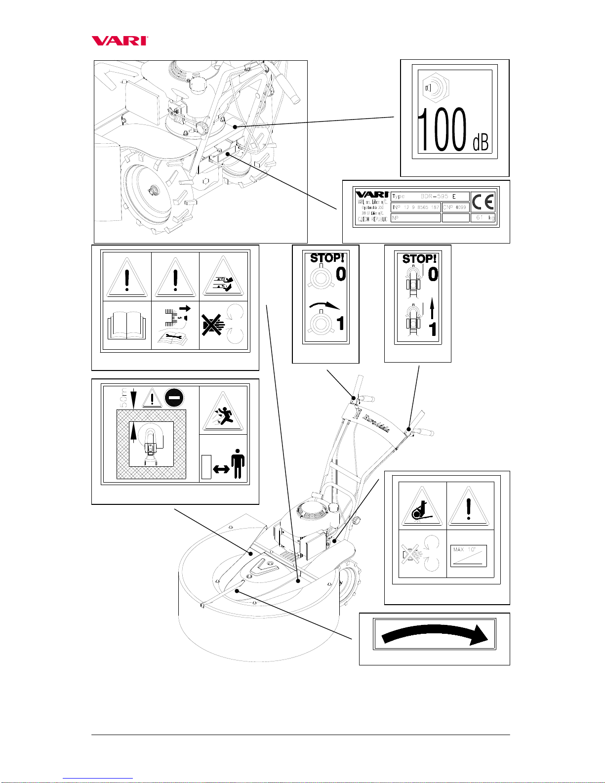
4.3 Safety pictographs..........................................................................................................7
5Machine: Its use, technical specification and description..................................................9
5.1 Use of the machine.........................................................................................................9
5.2 Technical specification...................................................................................................9
6Instructions for use........................................................................................................... 10
6.1 Machine assembly........................................................................................................10
6.2 Putting into operation...................................................................................................12
6.3 Starting the mowing disk..............................................................................................13
6.4 Machine travel.............................................................................................................. 13
6.5 Machine stop................................................................................................................15
6.6 Working with the machine...........................................................................................15
6.6.1 Working engagement of the machine...................................................................15
6.6.2 Mowing grass stands............................................................................................16
6.6.3 Problems at cutting...............................................................................................16
7Maintenance, care and storage........................................................................................17
7.1.2 Engine oil replacement.........................................................................................18
7.1.3 Table of machine lubrication................................................................................18
7.2 Tightening of bolted connections.................................................................................19
7.3 Replacement and sharpening of working knives..........................................................19
7.4 V-belt replacement and adjustment of tightening pulley.............................................20
7.5 Setting-up litz wires of pulley, brake and machine travel gear clutch.........................22
7.6 Driving problems: Diagnostics.....................................................................................24
7.9 Machine storage ...........................................................................................................26
7.10 Disposal of packaging and machine after service life expiration.............................26
8Instructions for ordering spare parts.................................................................................27
8.1 Machine casing.........................................................................................................29
8.2 Handlebars................................................................................................................31
8.3 Mowing disk drive ...................................................................................................33
8.4 Wheel driving gear...................................................................................................36
8.5 Gearbox.................................................................................................................... 38
Text and illustrations 2003 VARI,a.s.
Publication No. VL-079-2003

BDR-595 E EuroAdela
3
1Basic information
,Ask your dealer to provide unpackaging of the machine and briefing.
Fill in the following table with data on your machine. The data are important for ordering
spare parts.
It is advisable to have a copy of this page with all data on the machine purchase for the
case of loss or theft of the original record.
Type BDR-595 E
Trade name EuroAdela
Engine type HONDA GCV160
Machine Serial No./Year of
Manufacture /
Engine Serial No.
Date of delivery (sale)
Supplier
Address
Telephone/Fax/E-mail/Internet
Your notes:
Manufacturer reserves the right of technical modifications and machine innovations not
impacting function and safety of the machine. The alterations may not reflect in these
instructions for use.

BDR-595 E EuroAdela
4
2EC-Conformity Statement
EC-CONFORMITY STATEMENT
according to Act No. 22/1997 Gaz.
(as amended)
,Manufacturer:
VARI,a.s., Opolanská 350, 289 07 Libice nad Cidlinou, Czech Republic
Identification No.: 00660574
issues the following Statement at its own responsibility
,Machine
a) Name: Drum mower
b) Model: BDR-595 E
c) Brand: -
d) Serial No: 00001-99999
,Regulations to which the conformity was assessed:
Government Decree No.170/1997 Gaz. , Government Decree No.169/1997
Gaz., Government Decree No.9/2002 Gaz. (all Government Decrees as
amended), Directive 98/37/ES – Attachment No.1
,Person authorized for testing:
a) Name: Státní zkušebna zemědělských, potravinářských a lesnických strojů
b) Seat: Třanovského 22/II, Praha - Řepy
c) AO: 206 , accredited testing laboratory no.: 1054
d) Final report No.: 22 508 of 5 March 2003
,Harmonized technical norms, national technical standards and specifications:
ČSN EN 292-2+A1, ČSN EN 12733, ČSN CISPR 12
,
Technical documentation set containing the assessment of product compliance with the
regulations: No. STD/043/2003
,Manufacturer confirms that:
The above machine based on his concept and design, as well as the model introduced by us
into circulation, comply with relevant basic safety requirements of the government decrees.
Should there be machine alterations not approved by us, this Statement becomes void.
The product is safe under conditions of its common use specified by manufacturer.
Manufacturer has adopted measures to ensure conformity of all products introduced onto
the market with technical documentation and basic requirements.
,In Libice nad Cidlinou Date: 28 March 2003
signed by person authorized to act on our behalf:
Name: Jiří Belinger -CEO
Signature: Stamp:

BDR-595 E EuroAdela
5
3Introduction
Dear customer and user,
Thank you for the trust you have shown by purchasing our product. You have become owner
of machine from a wide range of machines and attachments made by ,a.s. as a system of
gardening, farming, small agricultural and communal technology.
Drum mower BDR-595 EEuroAdela meets with its design the latest European safety
standards and directives for this category of mowing machines. Construction of the protective frame
with screen around the entire mowing disk circumference does not prevent perfect cutting of the grass
and its continuous swathing on the right side of the machine. Thanks to this frame with the screen
which provides protection from possible fly-away stand fragments, the drum mower can also be used
inside towns and villages (while adhering to instructions listed under 4.1 Safety regulations). The
drum mower can also be favourably used at places where cutting of the high-grown grass must not
result in damage to young trees, shrubs, etc. such as in forest nurseries, orchards, ...
Please read the Instructions for use carefully. Following them properly, you will get our
product performing reliable work for years.
3.1 Warning
User is obliged to get acquainted with the Instructions for use and to follow all instructions for
machine operation so that the user’s and other persons’ health and property do not suffer any harm.
Safety instructions contained in this manual do not describe all situations or conditions
possibly occurring in practical use. Safety factors such as common sense, diligence and
scrupulousness are not included; it is assumed, however, that all persons authorized for machine
operation or maintenance do possess the intelligence.
The machine can be operated only by persons in good mental and physical condition. For the
professional use of the machine the machine owner is obliged to ensure a work safety training and
provide instructions on machine control for operators and to keep records on these trainings and
briefings. In addition, the machine owner is obliged to make a so called categorization of
operations according to the relevant national legislation.
Should some instructions in the manual be unintelligible, you are encouraged to contact your
dealer or directly the manufacturer of the machine. The contact address and telephone/fax connection
are to be found at the end of the manual.
Instructions for use supplied with the machine are an integral part of the machine. They have
to be available at any time, placed at a well accessible place with no risk of their damage. In the case
that the machine is sold to another person, the Instructions for use must be given to the new machine
owner. If the above conditions are not met, the manufacturer bears no responsibility for incurred
risks, accidents and injuries resulting from the machine operation.
The manufacturer bears no responsibility for damages caused by unauthorized and incorrect
use of the machine and for damages caused by any machine modifications not authorized by the
manufacturer.
To prevent injuries of operators and other people occurring in the vicinity of the machine, it is
absolutely crucial to follow safety regulations marked in the Instructions for use with the following
warning safety symbol:
,
As soon as you meet with this symbol in the
manual, read the attached instructions
carefully !

BDR-595 E EuroAdela
6
4Operation safety
4.1 Safety regulations
,This international symbol indicates important messages concerning safety. When you see
the symbol, be aware of a possible injury to yourself or to other persons and read attached
instructions carefully.
,The machine operator must be over 18 years of age. He (she) is obliged to get familiar
with the instructions for use of the machine and is supposed to be informed of the general
principles of work safety.
,Prior to carrying out any activities in the near vicinity of the machine, switch the engine
off and wait until the mowing disk stops moving! Before leaving the machine alone,
switch off the engine!
,Never let the engine running at maximum speed or idling for a long time with the
mowing disk drive clutch and travel wheels drive clutch being switched off! Components
of the machine drive (V-belt, belt pulley, clutch pulley, etc.) might get damaged!
,Prior to each employment of the machine, check its parts (working mechanism or its
casing in particular) for possible damage or loosening. Possible defects must be rectified
without any delay. Repairs are to be made only with original spare parts.
,Before using the machine, the stand must be cleared of solid bodies such as stones, wires,
loose construction debris, etc., which could be flinging up or which might damage the
machine. If these cannot be removed, don’t work the places.
,The machine is equipped with the rotating working tool. Maximum circumferential speed
is 60.3 m.sec-1. Therefore, see to it that other persons move at a safe distance from the
machine when it is in operation with regard to a possibility of mown stand or solid
objects flying away
,With respect to exceeded recommended values of noise and vibrations, you are warned to
observe the following instructions when working with the machine:
a) Protect your hearing by using suitable protective aids specified in CSN EN 352-1
(shell ear protectors) or CSN EN 352-2(plug ear protectors). Require the aids from
your dealer.
b) Work with the machine should be interrupted after max. 20 minutes for min.10
minutes. During these breaks, the machine operator must not be exposed to the effect
of another source of noise or vibrations.
,Machine operators should use working aids authorized to CSN EN 166 or CSN EN 1731
(tight-fitting garments, sturdy shoes, working gloves and protection glasses). Keep a safe
distance given by the handle.

BDR-595 E EuroAdela
7
,Don’t start the engine in enclosed spaces! Pay an increased attention when handling the
machine since the exhaust silencer remains hot after the engine has been switched off;
make sure there are no leakages and spills on engine parts when refuelling. If they
happen to occur, dry out the stained parts or wait until the petrol evaporates.
,When the machine is in operation, all other persons (children in particular) and animals
have to be outside the machine’s working space. The machine operator can continue
working only after they have been shown out to a safe distance of min. 50 meters (see
Pictograph 6).
,Removal of any protective equipment and machine casings is forbidden.
,Safe slope accessibility of the machine is 10°. Maximum inclination of engine at work is
20° for a longer time and 30° for a shorter time (up to 1 minute).
,All kinds of machine repair, adjustment, lubrication and cleaning are to be made with the
machine switched off and spark plug cable disconnected.
4.2 Declared and guaranteed noise and vibration values
Declared emission level of acoustic pressure A at the operator’s site LpAeq,T = 84 dB
(according to ČSN EN 836+A1/A2, Attachment H and ČSN EN ISO 11 201
Guaranteed level of machine’s acoustic performance LWA = 100 dB (according to
Government Decree No..9/2002 Gaz. )
Declared aggregative value of accelerated vibrations transmitted onto the operator’s hand-arm
ahv = 8,1 + 3,2 [m.s-2] (according to ČSN EN 836+A1/A2, Attachment G and ČSN EN 1033 .
4.3 Safety pictographs
User is obliged to maintain pictographs on the machine legible and to provide for their
replacement in case of their damage.
10 At work, keep the maximum permitted-safe slope accessibility of the machine
11 Switching on the mowing disk drive: „0“ = Mowing disk standing still; , „1“ = Mowing
disk turning
12 Switching on the machine travel: „0“ = Machine standing still; , „1“ = Machine moving
Pictograph no. Safety information description
1Label with manufacturing data
2Guaranteed level of machine’s acoustic performance
3Instructions for use to be thoroughly studied prior to machine use
4During machine maintenance, conductor should be disconnected from the spark plug
5Putting one’s hands or feet into the mowing disk working space is prohibited –Danger
of injury
6Entry prohibited for other persons and animals. Keep minimum safe distance from the
machine.
7Danger of injury by fly-away material fragments, chips, objects, etc.
8Arrow for the tool direction of rotation -right
9Putting one’s hands into the V-belt space is prohibited –Danger of squeezed limbs.

BDR-595 E EuroAdela
8
LwA
2.
1.
3. 4. 5.
6. 7.
8.
11.
12.
9. 10.

BDR-595 E EuroAdela
9
5Machine: Its use, technical specification and description
5.1 Use of the machine
Drum mower Model BDR-595 EuroAdela has been designed and manufactured to the
latest knowledge in the field of small gardening and farming machinery, its design meeting
the most recent European safety standards binding for this machine category. It also excels in
easy maneouvrability and problem-free maintenance.
The mower is meant for cutting thin-walled stalky grass stands of medium height up to
max. 80 cm on well-kept (i.e. annually mown) surfaces. The mown surfaces must be without
any solid articles in the stand and greater terrain roughness. The mower is not meant for park
treatment of grass stands neither for cutting stands with even a minimum representation of
woody plants arisen from self-seeding.
,Engagement width has to be at all times accommodated to the density of
mown stands
5.2 Technical specification
BDR-595 E EuroAdela Unit Value
Length (incl. protective screen) mm 1745
Width (incl. protective screen) mm 978
Height (incl. protective screen) mm 1120
Weight kg 61
Max. engagement width cm 56
Mowing disk speed (at max. engine rotations) min-12068
Circumferential speed of knives (at max. engine
rotations) m.s-160.3
Travel speed (at max. engine rotations) km.hr-12.7
Area performance (according to stand type) m2/hr 800-1400
Gear box oil filling litres 0.15
Oil grade API GL -4, GL –5
SAE 90, 80W -90
Engine type Unit Value
HONDA GCV 160 -- --
Cylinder volume cm3160
Drilling x Lift mm 64x50
Max. output at RPM kW/rpm 4.1/3600 (5.5HP)
Max. torque at RPM N.m/rpm 11.4/2500
Maximum engine speed adjustment rpm 3200 (+/-100)
Tank volume litres 1.1
Petrol (leadless) oct.no. 91-95
Oil filling litres 0.55
Oil SAE 15W-40
Spark plug -- NKG BPR6ES
-- BRISK LR15YC

BDR-595 E EuroAdela
10
6Instructions for use
6.1 Machine assembly
Ask your dealer to provide machine unpackaging and briefing.
Grip points for unpackaging the machine from the box: Front – Mowing disk; Rear – the
„U“ tube of the machine frame.
Should you do the machine assembly yourself, please follow the below instructions:
Note: Washer size (e.g. Ø6.4mm) is always presented as the diameter of washer hole.
1. Take the machine out from the box and all parts from the packages.
2. Slip the front part of screen frame (1a) into the rear part of screen frame (1b) and connect
them by means of M6x16 bolts (2) with small flat washers Ø6.4mm (3).
3. Put the assembled screen frame on a flat surface (table, floot, etc.) and slip the screen (4)
onto the longitudinal beam on the front part of screen frame with its back side out. Bolt
the screen (4) to the assembled apron frame by means of two bolts M6x16 (2) with
washers Ø6.6mm (5) and self-locking nuts M6 (6) with small flat washers Ø6.4mm (3).
Provide the bolt heads with plastic caps (7). Then sling the screen sides over the screen
frame so that they are in the position illustrated in Fig. 2a.
4. Turn the handlebars (8)so that the handrails point to the rear of the machine. Attach the
handlebars (8) onto the frame tubes at a required height by means of bolts with squares
(9), small flat washers Ø8.4mm (10) and plastic rosebits with internal tread (11). Fix the
Bowdens to the tubes of handlebars by means of two plastic tightening tapes.
Driving wheels
Engine
Handleba
rs
Mowing disk drive gear
lever with brake
Accelerator lever (adjustment
of engine speed)
Machine travel gear
clutch lever
Plastic rosebit to
adjust handlebars
height
Upper
casing
Figure 1: Drum mower BDR-595 E EuroAdela
Starter grip
Side apron
Front grip handrail (e.g. for
lifting the machine etc.)
Rear grip points
(for steering, lifting
or loading the
machine)
Apron

BDR-595 E EuroAdela
11
5. Put the apron with frame into the cut-out in the upper casing (13). Then put the casing
with the apron frame on the machine and bolt it with two nuts M8 (14) with large flat
washers Ø9mm (10). Provide the nuts with plastic caps (19). The apron frame will be
screwed to the machine under engine front with M6x20 bolts (20) with small flat washers
Ø6.4mm (3). Provide the heads of M6x20 bolts with plastic caps (7).
6. Then bolt the apron to the upper casing by means of bolts M6x16 (2) with large flat
washers Ø6.6mm (5) and self-locking nuts M6 (6). Provide the M6x16 bolt heads with
plastic caps (7).
7. Bolt the mud guards (17) to the upper casing (13) by means of bolts M6x16 (2), self-
locking nuts M6 (6) and large flat washers Ø6.6mm (5).
Apron around the
mowing disk
Figure 2a :
Apron assembly
4
7
2
5
3
6
1b
1a
2
3

BDR-595 E EuroAdela
12
6.2 Putting into operation
,The machine can be delivered without working fillings of the engine (as
depending on varied national regulations)!
,First read the instruction for engine use thoroughly! You can prevent a possible
damage to the engine.
1. Check oil in the engine and/or fill the engine with the prescribed oil type and volume.
Fill the tank with the prescribed amount and type of petrol.
9
13
10
11
10
2
17
6
5
Figure 2b: Machine assembly
5
20
7
19
14
2
5
7
5
6
8
3

BDR-595 E EuroAdela
13
2. Move the accelerator lever into the front position (CHOKE). Start the engine by pulling
on the manual starter (instructions for starting see the guidelines for engine use).
3. Let the new or cold engine running for about 30 seconds on the choke (accelerator lever
in the CHOKE position); then move the accelerator lever into the position MAX and let
the engine running in this position for about 30 seconds.
,Don’t leave the machine alone when doing this.
6.3 Starting the mowing disk
,When starting the engine, the two levers on the handlebars must be in the off
position.
1. Start the engine. When doing this, follow the instructions presented in the operating
manual for engine use.
2. Set-up maximum engine rotations by accelerator lever on the right handrail. (Should the
engine be cold, let it warm up at maximum speed for about 1 minute.)
3. Grasp the left handlebar grip. Then slowly press the mowing disk drive gear lever on the
right handlebar grip with your right hand.
,Press the lever slowly up to two thirds of the stroke so that the mowing disk can
start rotating and the engine does not stall.
The start of the mowing disk is accompanied with a partial slippage of the V-belt and
with the related phenomena such as whistling, rattling, etc. which usually disappear after the
belt has started properly moving.
4. After the mowing disk has started turning, press the lever completely to the handrail and
hold firm.
Note: In a new or cold engine, engine stalling may occur at several first mowing disk
drive starts. The phenomenon will disappear after the engine has got warmer. If the disk
drive cannot be started even after the engine has got warm, follow the table presented in
chapter 7.6 for diagnostics.
6.4 Machine travel
The travel gear is to be switched on by a lever on the left handrail. Press the lever down
to the handrail and the machine starts immediately moving forward. You have to start slowly
walking as soon as you have pressed the lever down and the machine has started its travel.
,The machine may start moving with a slight jerk; be prepared for that.

BDR-595 E EuroAdela
14
Note: all four main positions of accelerator lever are locked by means of a simple hollow-lug
system in the lever body.
Mowing disk drive clutch
lever and brake lever
Machine travel
clutch lever
Accelerator lever
(engine speed
adjustment)
Bowden cable of
machine travel
Mowing disk brake
Bowden cable
Bowden cable of
tightening pulley of
the mowing disk
drive V-belt
Right
handrail
Left handrail
STOP position of accelerator lever –
Engine not running MIN
(turtle) position of accelerator
lever –Engine running idle
MAX (hare) position of accele
rator lever
–Engine running at maximum speed CHOKE
position of accelerator lever (for cold
engine start only) –Engine running on choke
Figure 3: Handlebars and accelerator lever

BDR-595 E EuroAdela
15
6.5 Machine stop
,Prior to performing any activities in the near vicinity of the machine, switch off the
engine and wait until the mowing disk stops! Always switch the engine off before
leaving the machine.
,Never let the engine running at maximum speed or idling with the mowing disk
drive gear clutch released and with the released clutch of travel wheels drive gear
for a long time! Machine drive components (V-belt, belt pulley, clutch pulley, etc.)
might get damaged!
If you wish to stop the machine travel, release the lever on the left handlebar grip. The
machine travel will stop but the mowing disk is still rotating. The mowing disk drive will
switch off immediately after you have released the lever on the right handlebar grip. The
mowing disk will be stopped by safety brake.
Engine is to be switched off by pushing the lever into the STOP position.
,In the case of any critical situation, release your hold on the handlebars
immediately. The levers will return to their zero position, the machine and the
mowing disk will come to a stop (while engine is still running at adjusted rotations;
this is why it is to be switched off by pushing the lever into the STOP position as
soon as possible!)
6.6 Working with the machine
6.6.1 Working engagement of the machine
,Prior to the machine use, the stand must be cleared of solid bodies such as stones,
wires, loose construction debris, etc., which could be flung or might otherwise
damage the machine. Should these be impossible to remove, avoid working the
places.
,Mowing engagement width has to be at all times accommodated to stand density!
On the upper surface of the apron, there is a
yellow strip placed on the right side to indicate
the maximum working engagement of the
mowing disk on the right. Edge of the to-be-
mown stand should not exceed the boundary
given by the strip (see Figure).
Warning: When mowing, make sure that the
lower disk is permanently pushed against the
Strip on the apron
To-be-mown stand

BDR-595 E EuroAdela
16
ground and does not rebound. Disk rebounding results in uneven stand mowing
6.6.2 Mowing grass stands
Set the engine to maximum speed, let the mowing disk rotate at maximum speed
(starting the mowing disk see chapter 6.3) and get the machine into motion (see chapter 6.4)
facing the stand to be cut. The mown grass is thrown away by the mowing disk to the right
side onto the screen which forms a swath. Grass leaves the space under the screen from in
front of the right wheel.
The only correct way how to proceed at cutting the grass stand is to have the to-
be-mown grass at all times on the left side of the machine (see Figure).
It is adviseable to drive the machine along the slope contour lines for cutting.
Keep in mind, however, that the maximum machine tilt permitted is 20° (long-term)
and 30° (short-term)!
If the stand is very dense, grown through, rotten or lodged, the machine working
engagement width must be reduced accordingly so that the mowing disk rotations are not
being excessively reduced and the cutting quality impaired.
6.6.3 Problems at cutting
Choking of the space under the upper casing and apron with grass can show as follows:
a) Engine markedly loosing speed but not stalling: machine travel to be switched off
immediately (lever on the left handrail); drive in reverse gear just a bit with a
simultaneous slight lifting of the machine front (by pushing down on the handlebar
handrails). The casing space will do itself a partial clearance of excessive grass matter.
Then drive the machine against the stand again (see chapter 6.4).
,Be very careful while lifting the machine and at reverse driving!
b) Engine loosing speed and stalling: release the both levers on the handlebars, lift the
machine front part by pushing down on the handlebars and drive a bit in reverse. Clear
the space under the upper casing and spread the cut grass across the ground. Start the
engine, switch on the mowing disk drive (see chapter 6.3) and once again drive the
machine against the stand (see chapter 6.4).
,The engine must always be switched off when clearing the space under the upper
casing and screen!
,Tilt the machine always only backwards onto the handlebars. Be very careful while
moving in the space beneath the lifted machine! Secure the machine against
spontaneous motion!
,Be very careful while cleaning the space under the upper casing and screen. Cutting
edges of knives are sharp. You should wear protective gloves or you can also use a
piece of branch etc.

BDR-595 E EuroAdela
17
7Maintenance, care and storage
To ensure a long-term satisfaction with our product, it must be given proper care and
maintenance. Regular maintenance of the machine will prevent its early wear ensuring at the
same time a correct functioning of all its parts.
Follow all instructions for intervals of machine maintenance and adjustment. It is adviced
that you keep records on the number of machine working hours and on the conditions in
which the machine was working (for service purposes). Similarly as the current maintenance,
the post-season maintenance should be entrusted to one of our authorized service workshops
if you are not certain of your own technical skill.
,Regarding the machine weight, its maintenance and adjustment are to be made by a
team of two persons.
7.1 Machine lubrication
7.1.1 Gear oil replacement and refilling
,When replacing oils, follow the basic hygienic principles, regulations and laws
on environment protection.
The gearing works in an oil bath. Oil condition should be checked once a month (oil
plugs see Fig. 4).
Minimum grade of gear oil according to API should be GL-4, GL-5; according to SAE:
90 or 80W-90.
Oil replacement in a new machine is to be made after the first 5 hours of operation and
then after 100 working hours or after the season. This will ensure that the gears will not
suffer excessive wear. The exchange interval can be extended up to 130 hours (the running-
in time of 5 hours must be adhered to) in higher oil grades (API GL-5, SAE 80W-90).
Czech oils fully meeting the requirements are MOGUL TRANS 90 or MOGUL TRANS
80W-90.
Oil replacement should be made when the gearbox is warm, oil can be drained easily.
1. Clean around the oil plugs. Underlay the machine and secure it so that a space is created
under the machine for a vessel to collect oil.
2. Loosen the pour-in plug on the rear wall of the box and the drain plug in the bottom of
the gearbox (spanner No. 19).
3. After the oil has been drained, screw back the drain plug in the bottom of the box. Fill the
gearbox with the new oil (it is adviced to use a funnel with flexible tubing). Oil level
should reach to the lower edge of the hole. Then screw the pour-in plug back. If the seals
under the plugs are damaged, replace them with new ones.

BDR-595 E EuroAdela
18
7.1.2 Engine oil replacement
See the guidelines for engine operation. To drain the oil, the machine should be either
inclined onto the side with the pour-in neck with oil gauge, or the engine should be
dismounted from the machine (see chapter 7.4 a,b,d).
7.1.3 Table of machine lubrication
Both swivel seatings of rotary lever in
the gearbox min 1x a
month yes silicon oil in
atomizer 5.1
Tightening pulley arm pin (after
disassembling upper casing) min 2x yes grease,
engine oil 5.2
Brake lever seating near the front belt
pulley (accessible after upper casing
disassembly) min 2x yes grease,
engine oil 5.3
Machine lubrication During the
season After the
season Lubricant Figure
All cables
-input points to Bowdens
-output points from adjustment
bolts
min 2x
min 2x yes
yes silicon oil in
atomizer -
Plug to pour oil into the
gearbox
Plug to drain oil from the gearbox
Figure 4: Oil plugs

BDR-595 E EuroAdela
19
7.2 Tightening of bolted connections
Check the bolted connections for proper tightening. Check tightening of bolts
fastening the knives in the upper disk and bolts fastening the lower disk onto the flange prior
to any machine use.
7.3 Replacement and sharpening of working knives
If the cutting edges of working knives show wear or a damage to knives results in
machine vibrations, the cutting edges must be renewed or the knives replaced.
,The machine must be standing on a firm support plate and must be secured so that
the knife can be easily accessible and an unexpected spontaneous machine motion
cannot occur.
,Be very careful when dismounting the knives. Their cutting edges are sharp. Protect
your hands with working gloves.
,The engine must be switched off and the cable end connector to the spark plug
disconnected!
1. Turn the screen sides over to back or disassembly the screen with the frame
Figure 5.2: Tightening pulley arm pin
Figure 5.1: Rotary clutch lever
Figure 5.3: Brake lever seating
Figure 5: Lubrication

BDR-595 E EuroAdela
20
2. Hold the upper disk so that it does not turn and dismount the knife bolted connection by
using the barrel spanner No. 16 and flat wrench No. 17.
3. Take the knife and parts of knife seating out of the mowing disk. Level the blade and
sharpen the knife cutting edges. Inclination of the sharpened blade should be 30° with
respect to the lower plane of the knife.
,Should some of knives be bent or showing a considerable wear, you must always
replace all knives in the mowing disk!
4. Screw back the bolt with the filler, knife and flat washer. Than screw on the nut.
5. Hold the bolt head with the barrel spanner No. 16 and tighten the nut. All knives must
freely rotate on the bolts. The knives have blades on both sides; when one side is worn
out, the knife can be reversed and the blade of the other side can be used. When replacing
the knife, replace also all damaged parts of the knife clamping (see Fig. 6).
Note: Manufacturer does not answer for damages caused by the machine if the knives
were repaired by unskilled persons without the use of the original spare parts. There is a
“VARI“ stamp on the knife, which identifies the manufacturer and is at the same time a
control mark indicating that the knife is an original spare part.
7.4 V-belt replacement and adjustment of tightening pulley
The V-belt should be replaced according to its wear (cracked sides, torn belt, sides worn
out down to belt carrier fibres, belt pulled out of shape) or after about 100 hours of operation
at the maximum. In this machine, the belt stretched to maximum is considered a belt in which
the distance between the internal belt surfaces is lesser than 7 mm (with the pressed lever of
mowing disk drive clutch) – see Fig. 7.
The replacement procedure is as follows:
Nut M10
Order no.189 561
Washer
Order no. 189 587
Knife
Order no. 189 060
Washer 10.5
Order no. 131 518
Bolt M10x30
Order no. 189 545
Figure 6: Knife clamping on the mowing disk
Table of contents
Other Vari Lawn Mower manuals

Vari
Vari Trimmer 50 User manual

Vari
Vari BDR-1200 User manual

Vari
Vari Adela PRO BDR-720 User manual

Vari
Vari Lucina Max BDR-620 User manual

Vari
Vari F-530.1 User manual

Vari
Vari Samson - 56 BK User manual

Vari
Vari FM33 User manual

Vari
Vari Agatha User manual

Vari
Vari Liza DS-520 User manual

Vari
Vari BDR-620 User manual
Popular Lawn Mower manuals by other brands

Snapper
Snapper NZM19482KWV, NZM21522KWV, NZM2 Safety instructions & operator's manual

Scag Power Equipment
Scag Power Equipment CHEETAH II Operator's manual

Fort
Fort MICRO 2000 Use and maintenance instructions

SIP
SIP SILVERCUT DISC 340 F FC manual

Flymo
Flymo HOVER COMPACT 300 quick guide

MTD
MTD 115-102-000 owner's guide