10
VERIFICHE
Effettuata la corretta selezione del variatore, si consiglia di pro-
cedere alle seguenti veriche:
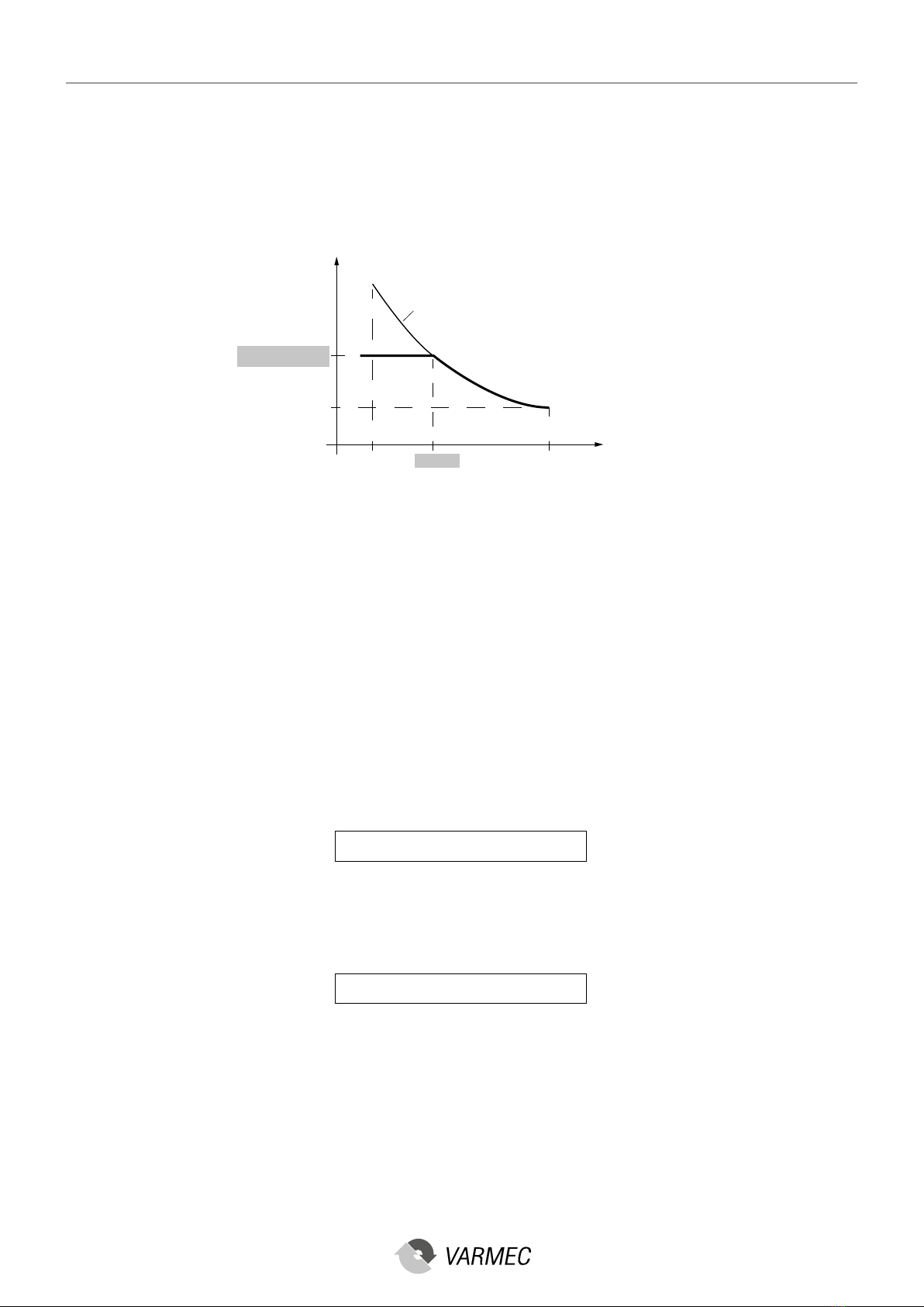
Momento torcente massimo
I sovraccarichi istantanei previsti dall’applicazione non devono
essere superiori al doppio dei valori di momento torcente del
variatore riportati a catalogo.
Carichi radiali e assiali
I carichi radiali e assiali agenti sugli alberi lenti devono rientrare
nei valori di catalogo ammessi.
CHECK POINTS
Once you have correctly chosen the type of variator, it is then
advisable to check that the following apply:
Maximum torque
The maximum torque at instantaneous peak overloads of the
application must not be higher than the double of the torque
values of the variator given in this catalogue.
Radial and thrust loads
Radial and thrust loads on the output shafts must be within the
permissible loads given in this catalogue.
CARICHI RADIALI E ASSIALI RADIAL AND AXIAL LOADS
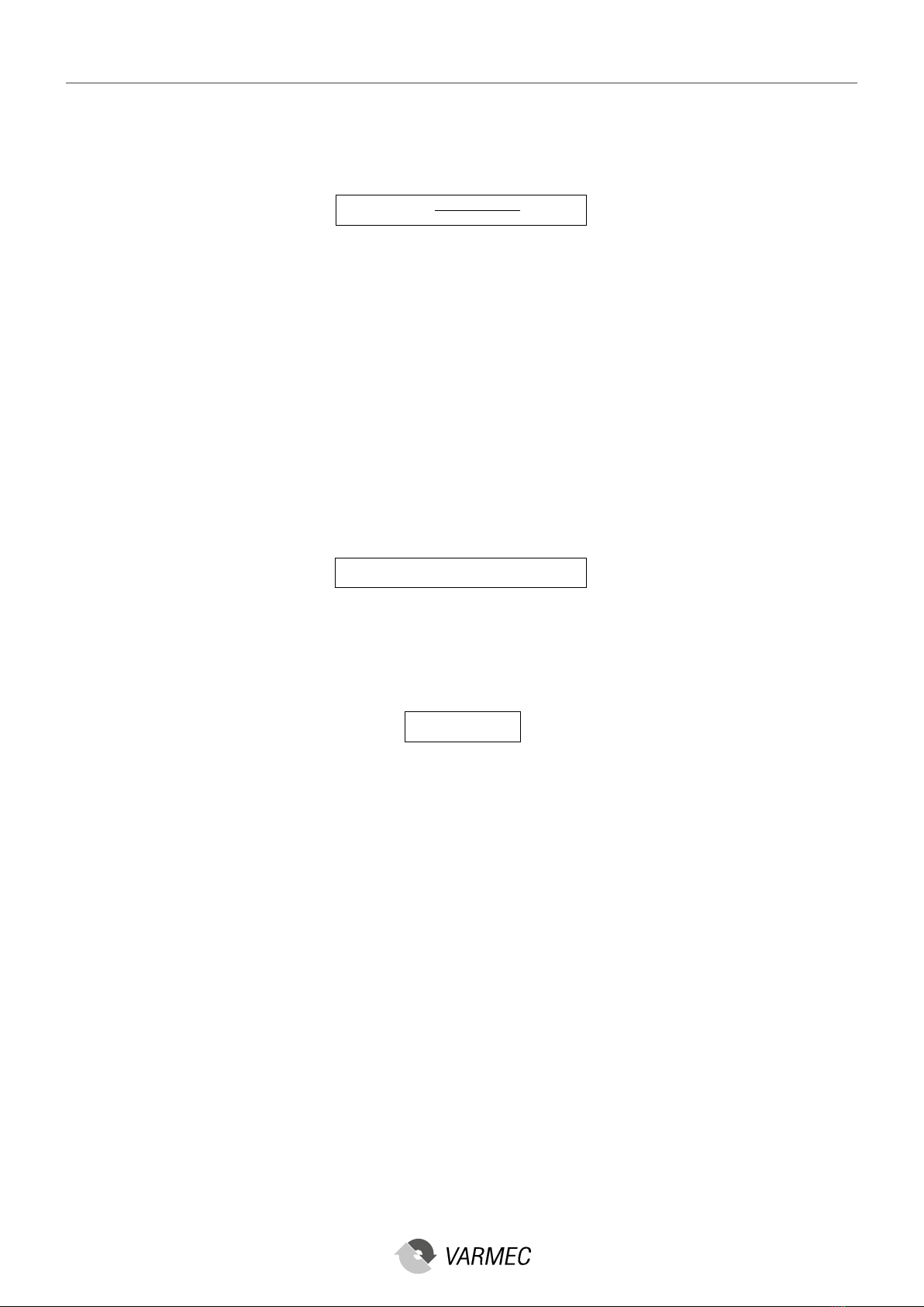
Gli alberi di uscita dei variatori possono essere soggetti a cari-
chi radiali, la cui entità può essere calcolata, in base al tipo di
trasmissione realizzata, con la seguente formula:
2000 .M2.C
D
Frc =
Frc Carico radiale di calcolo sull’al-
bero lento
M2Momento torcente sull’albero
lento
D Diametro primitivo della ruota
per catena, ingranaggio, puleg-
gia, ecc.
C = 1 per trasmissioni a catena
C = 1.25 per trasmissioni a ingranaggi
C = 1.5 per trasmissioni a cinghie
dentate
C = 2.5 per trasmissioni a cinghie
trapezoidali
C = 3.5 per trasmissioni a ruote di
frizione
Frc ≤ Fr2
Fa2 = 0.2 .Fr2
I valori riportati nelle tab. dei dati tecnici, rappresentano i carichi
radiali massimi Fr2, sopportabili dal variatore, pertanto dovrà
essere rispettata la seguente condizione:
• I carichi indicati sono riferiti alla mezzeria della sporgenza dell’al-
bero lento e valgono per qualunque direzione di applicazione e
senso di rotazione.
• Contemporaneamente al carico radiale Fr può agire un cari-
co assiale Fa pari a:
• Nel caso in cui il valore del carico radiale sia nullo, si può con-
siderare il carico assiale ammissibile pari al 50% del valore
del carico radiale massimo sull’albero.
Output shafts of speed reducers can be subject to radial loads,
the value of which can be calculated – based on the type of
transmission carried out – using the following formula:
Frc Calculated radial load on output
shafts
M2Transmitted torque at output
shafts
D Diameter of chain wheel, gear
pulley etc.
C = 1 for chain transmission
C = 1.25 for gear transmission
C = 1.5 for timing belt transmission
C = 2.5 for V-belt transmission
C = 3.5 for clutch wheel transmission
The values given in table of technical data represent the maximum
radial loads that the speed reducer can withstand and therefore
the following condition must always apply:
• The given loads refer to the centre of the output shaft and are
valid for any applicational direction and sense of rotation.
• An axial load Fa can act simultaneously with a radial load
equal to:
• If the value of the radial load happens to be zero, the per-
mitted axial load can be regarded as being 50% of the max
radial load on the shaft.
• Se i valori di carico radiale e assiale ammissibili risultassero
inferiori a quelli desiderati, vi preghiamo di contattare il nostro
servizio tecnico.
• If the values of admissible radial and axial loads are lower than
desired, please consult out technical service department.