manuals.online logo
Brands
  1. Home
  2. •
  3. Brands
  4. •
  5. VAS
  6. •
  7. Automobile Accessories
  8. •
  9. VAS SL2600 User manual

VAS SL2600 User manual

1 www.vanracking.com.au - issue02
LADDER RACK
FITMENT
MAX LADDER LOAD: 40KG.
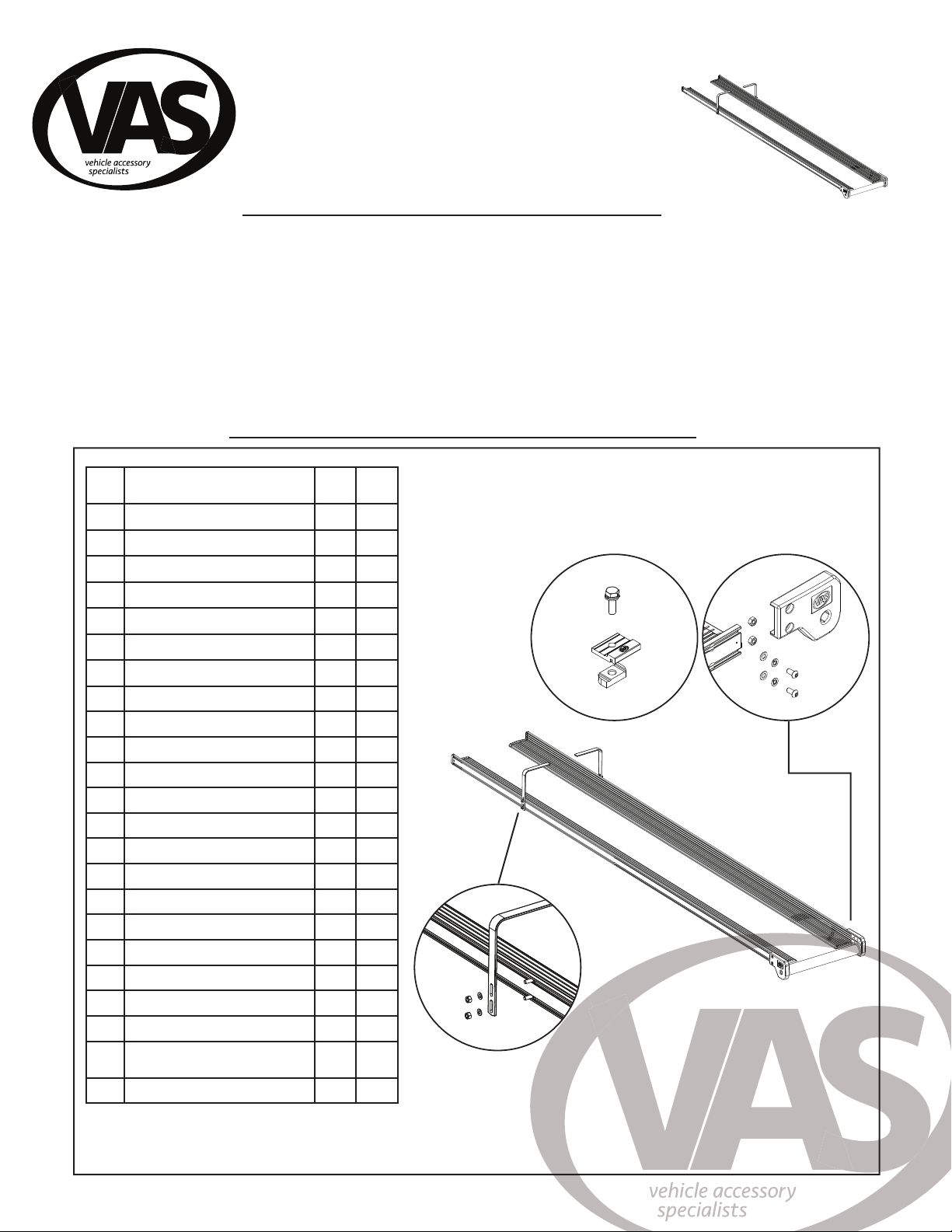
Parts list:
Item Part 2.6m
Step
3m
Kit
1a Left Rail Assembly - VA-001 0 1
2a Right Rail Assembly - VA-002 0 1
1b Left Rail Assembly 2.6m - VA-006 1 0
2b Right Rail Assembly 2.6m - VA-007 1 0
3 Front End Cap LH - C108 1 1
4 Front End Cap RH - C109 1 1
5 Rear End Cap LH - C110 1 1
6 Rear End Cap RH - C111 1 1
7 End Cap Screw3x8 - F037 8 8
8 Rear Roller End Cap L - C112 1 1
9 Rear Roller End Cap R - C113 1 1
10 M8x16 Button Screw - F016 4 4
11 M8 Flat Washer - F017 8 8
12 M8 Spring Washer - F018 4 4
13 M8 Hex Nut - F045 4 4
14 Ladder Hoop - C180 2 2
15 M8x20 Hex Screw - F046 4 4
16 M8 Nyloc Nut - F042 4 4
17 Roller 470mm - VA-003 0 1
18 Roller 680mm - VA-005 1 0
19 Locking Tabs - C097 12 12
20 M8x25 Hex Combination Bolts -
VA-004
12 12
21 M8 Channel Nut 12 12
1 - Small phillips head
screwdriver.
2 - 5mm allen key
3 - 13mm spanner
4 - Tape Measure
5 - 13mm socket
wrench (for ladder lock)
Important information:
- Narrow and heavy loads are to be carried near the crossbar mounts.
- Loads which overhang shall conform to any relevant state laws.
- Check tie down strap tension every 50kms as loads can shift and resettle
- Do not use elastic straps to secure a load.
- Specialised equipment carriers for specic products should always be used. I.e Ladder rack.
Note: The handling characteristics of a vehicle will change when a carrier system is tted. Driving techniques should be altered to allow for these changes,
reducing speed, cornering and allowing longer braking distances.
- Roof bars can be removed when not in use.
- Store spare ladder lock key in a safe place.
- Always store lock in housing to avoid damage to vehicle.
- The key must be inserted in the lock and turned clockwise to both open and close the ladder lock.
1. 2.
3.
4.
19.
5.
17/18.
6.
15.
8.
10.
20.
16.
9.
12.
14.
13.
11. 8/9.
11.
21.
2 www.vanracking.com.au
VAN RACKING MOUNT FITMENT
NOTE: For installation of the ladder lock kit, before tting front end caps,
slide the 2 M8 hex bolts into the rail (found in ladder lock kit).
Step 1
Insert the rail end caps and x with 3x8 xing screws, item No.7. A small phillips head screw driver will be required.
1: 2:
M8 Flat Washer
M8 Nyloc Nut
Cable Clamp
Block
Braided
Cable
Optional: If you have purchased ladder locks, please proceed with tting at step 1, otherwise begin at step 2.
1 - Assemble the cable and cable clamp onto the installed hex bolts. 2 - Tighten the hardware in place with a 13mm socket wrench in the appropriate area.
M8 x 20mm Hex Bolt
3 www.vanracking.com.au
VAN RACKING MOUNT FITMENT
Step 2
1 - Slide 2 hex nuts in the rear of each rail assembly as shown.
2 - Fix the roller end caps onto place using the M8 hardware listed below. Tighten the hard-
ware with a 5mm allen key.
Step 3
1 - Slide 2x M8 x 20mm hex bolts into the side of each rail assembly.
2 - Place a ladder loop over the installed bolts, xing them in place with M8 at washers and nyloc nuts. Do not completely tighten at this stage to allow for
adjustments.
M8 Hex Nut
M8 Hex Nut
M8 x 16mm btn Head Screw
M8 Spring Washer
M8 Flat Washer
M8 x 20mm Hex Screw
M8 Nyloc Nut
Step 4
Place the two rails onto the roof of the vehicle. Be sure that the rear door when opened, does
not contact the ladder rack. Make sure the rear door doesn’t
connect with ladder rack.
8-10Nm
4 www.vanracking.com.au
VAN RACKING MOUNT FITMENT
Step 5
With the ladder rack rails in the approximate position, insert the
roller between the rear mouldings as shown.
Step 6
1 - Assemble the locking tabs.
2 - Place 4x locking tabs (2x each rail) onto the ladder rack. Lock in
place with a 13mm spanner.
Combination bolts
Locking Tabs
Channel Nut
The locking tabs
clamp down on the
rails.
Channel nuts are situated
across the bar.
2600
680
385
NOTE: For 2.6m step ladder kits, taper the ladder rack as shown.
680mm
2600mm
385mm
5 www.vanracking.com.au
VAN RACKING MOUNT FITMENT
Step 8
Step 7
Install both sections of the retention strap into the rear crossbar. These sections should be xed between the two halves of
the ladder rack. Tighten with a 13mm wrench.
Channel nuts are situated
across the bar.
Place the restraint
kit between the
rails.
Make sure all hardware is tightened
in place. Finalise the ladder hoop
position and x.
230mm

This manual suits for next models

1

Popular Automobile Accessories manuals by other brands

Magneti Marelli AC161 Installation instruction

Magneti Marelli

Magneti Marelli AC161 Installation instruction

FDI uEZ GUI Start here

FDI

FDI uEZ GUI Start here

JCROffroad JT Install instructions

JCROffroad

JCROffroad JT Install instructions

Rostra VOXXElectronics 250-1930 owner's guide

Rostra

Rostra VOXXElectronics 250-1930 owner's guide

TOP VEHICLE TECH GR3FORD5 installation manual

TOP VEHICLE TECH

TOP VEHICLE TECH GR3FORD5 installation manual

Safe Fleet PRIME DESIGN AR-2000-BLK manual

Safe Fleet

Safe Fleet PRIME DESIGN AR-2000-BLK manual

Skoda Fabia Combi 5J Fitting instructions

Skoda

Skoda Fabia Combi 5J Fitting instructions

Camcar 40077 Al Mounting instructions

Camcar

Camcar 40077 Al Mounting instructions

Camcar 40089 AL Mounting instructions

Camcar

Camcar 40089 AL Mounting instructions

Impac Tradesman 2000 installation manual

Impac

Impac Tradesman 2000 installation manual

DVB OFFROAD BRSB-01 installation manual

DVB

DVB OFFROAD BRSB-01 installation manual

Safari Snorkel SS385HF installation guide

Safari Snorkel

Safari Snorkel SS385HF installation guide

ULTIMATE SPEED 279746 Assembly and Safety Advice

ULTIMATE SPEED

ULTIMATE SPEED 279746 Assembly and Safety Advice

SSV Works DF-F65 manual

SSV Works

SSV Works DF-F65 manual

ULTIMATE SPEED CARBON Assembly and Safety Advice

ULTIMATE SPEED

ULTIMATE SPEED CARBON Assembly and Safety Advice

Witter F174 Fitting instructions

Witter

Witter F174 Fitting instructions

WeatherTech No-Drill installation instructions

WeatherTech

WeatherTech No-Drill installation instructions

TAUBENREUTHER 1-336050 Installation instruction

TAUBENREUTHER

TAUBENREUTHER 1-336050 Installation instruction

manuals.online logo
manuals.online logoBrands
  • About & Mission
  • Contact us
  • Privacy Policy
  • Terms and Conditions

Copyright 2025 Manuals.Online. All Rights Reserved.