31
1968 FORDF-100 ASCENDER, BND
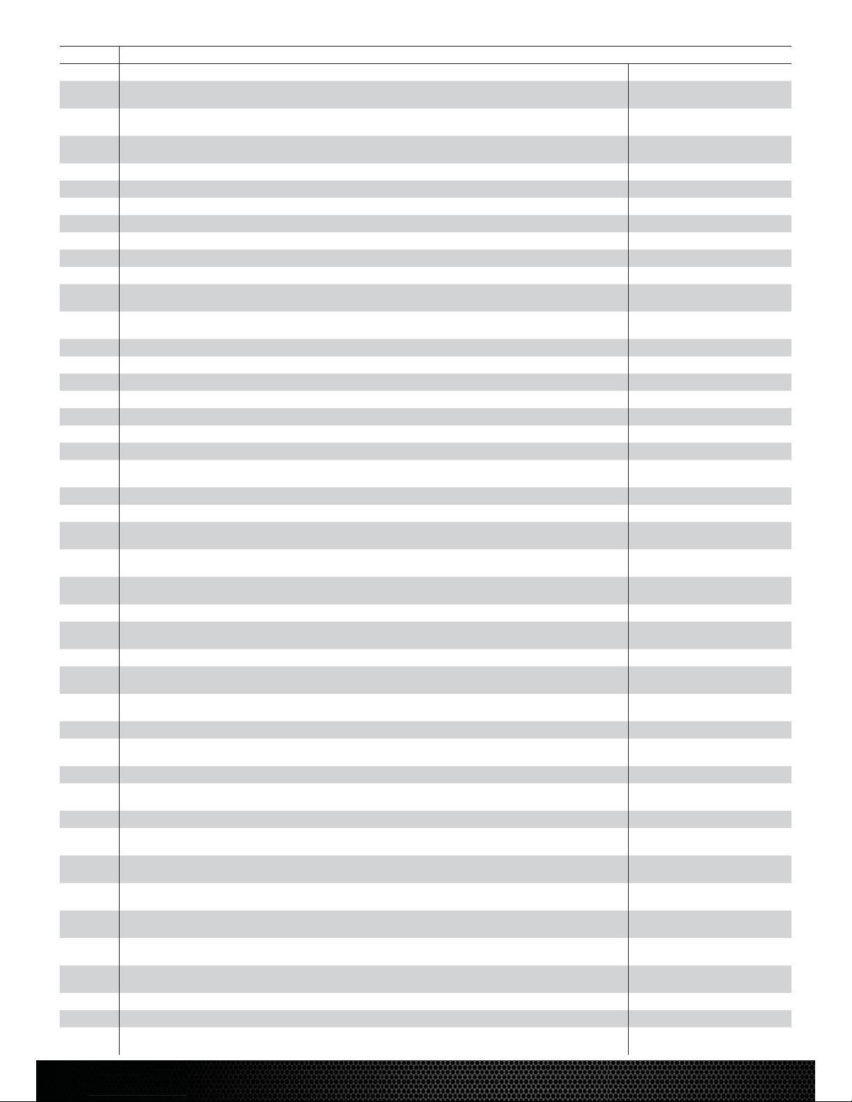
Replacement Parts List • Teileliste • Liste des pièces de rechange • Elenco dei ricambi
Part # English Deutsch Français Italiano
LOS4114 48 Pitch Pinion Gear, 14T 48 Pitch Ritzel, 14T Pignon moteur 48DP, 14T 48 Pitch pignone, 14T
DYNS2210 Waterproof 60A Forward/Reverse
Brushed ESC
Wasserdicht 60A Vorwärts / Rückwärts
gebürstet ESC
Étanche à l'eau 60A avant / inversé ESC
brossé
Impermeabile 60A ESC spazzolato in
avanti / invertito
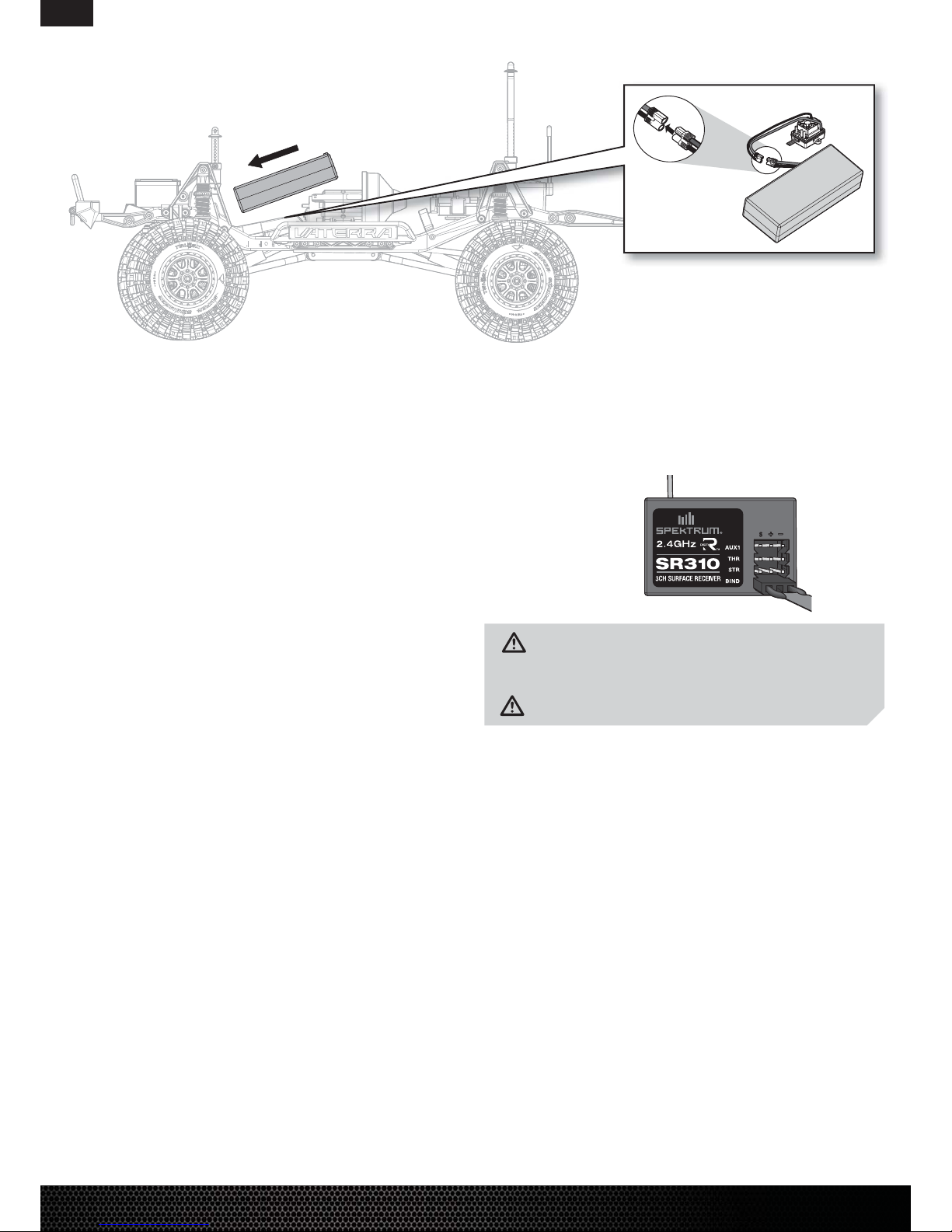
SPMSR310 SR310 DSMR 3 Channel Sport
Receiver SR310 DSMR 3 Kanal Sportempfänger Récepteur sport SR310 DSMR à 3 canaux Ricevitore sportivo SR310 DSMR 3
canali
SPMS605 9KG Servo, Waterproof, Metal Gear,
23T
9KG Servo, wasserdicht, Metallgetriebe,
23T
9KG Servo, imperméable à l'eau, équipement
métallique, 23T
Servo 9KG, impermeabile, ingranaggio
del metallo, 23T
TLR255002 Button Head Screws, M2.5x10mm (10) Halbrundschrauben, M2,5x10mm (10) Vis à tête bombée, M2,5x10mm (10) Viti a testa tonda, M2.5x10mm (10)
TLR255006 Button Head Screws, M4x10mm (10) Halbrundschrauben, M4x10mm (10) Vis à tête bombée, M4x10mm (10) Viti a testa tonda, M4x10mm (10)
TLR5903 Button Head Screws, M3 x 10mm (10) Halbrundschrauben, M3x10mm (10) Vis à tête bombée, M3x10mm (10) Viti a testa tonda, M3 x 10mm (10)
TLR5904 Button Head Screws, M3 x 12mm (10) Halbrundschrauben, M3x12mm (10) Vis à tête bombée, M3x12mm (10) Viti a testa tonda, M3 x 12mm (10)
TLR5909 Button Head Screws, M3 x 16mm (10) Halbrundschrauben, M3x16mm (10) Vis à tête bombée, M3x16mm (10) Viti a testa tonda, M3 x 16mm (10)
TLR5962 Flathead Screws, M3 x 10mm (10) Flachkopfschrauben, M3 x 10mm (10) Vis à tête plate, M3x10mm (10) Viti a testa piatta, M3 x 10mm (10)
TLR5964 Flathead Screw, M3 x 16mm (10) Flachkopfschrauben, M3 x 16mm (10) Vis à tête plate, M3x16mm (10) Viti a testa piatta, M3 x 16mm (10)
VTR230055 Ascender Roll Cage Set w/Alum
panels (290mm)
Ascender Roll Cage Set mit Alu-Verkleid-
ung (290mm)
Arceau cage Ascender avec panneaux alu
(290mm)
Set gabbia antiribaltamento Ascender
Set c/pannelli allum. (290mm)
VTR230057 1968 Ford F-100 Pickup Cab Set Clear:
ASN
1968 Ford F-100 Pickup Cab Set
transparent: ASN
ASN - Carrosserie transparente 1968
Ford F-100 Pickup
Set cabina trasparente 1968 Ford F-100
Pickup: ASN
VTR231033 Chassis Frame Rail Set: ASN Baugruppe Chassisrahmenschiene: ASN ASN - Set de longerons de châssis Set rotaie telaio: ASN
VTR231034 Chassis Brace Set: ASN Chassisstrebe Set: ASN ASN - Set de renforts de châssis Set supporto telaio: ASN
VTR231035 Shock Tower Set FR/RR: ASN Stoßdämpferbrücke Set v/h: ASN ASN - Support d'amortisseur Av/Arr Set torre ammort: ASN
VTR231036 Bumper Set FR/RR: ASN Stoßstangenset v/h: ASN ASN - Set de parechoc Av/Arr Set paraurti FR/RR: ASN
VTR231037 Receiver Box & ESC Tray: ASN Empfängerbox & Reglerhalter: ASN ASN - Boite de récepteur et platine de contrôleur Sede scatola ricevente ed ESC: ASN
VTR231038 Battery Tray, Mounts & Strap: ASN Batterieeinschub, -träger & -lasche: ASN ASN - Support de batterie, fixations et sangles Sede batteria, supporti e cinghia: ASN
VTR232001 Transmission Case: Twin Hammers Getriebegehäuse: Twin Hammers Twin Hammers - Boitier de transmission Scatola trasmissione: Twin Hammers
VTR232013 Drive Shaft Yoke, Cup & Hardware (1):
Twin Hammers
Antriebswellenmitnehmer und Zubehör
(1): Twin Hammers
Twin Hammers - Coupelle de cardan avec
croisillon et visserie (1)
Giogo albero trasm., coppa e viteria (1):
Twin Hammers
VTR232017 Transmission Shaft Set: Twin Hammers Antriebswellenset: Twin Hammers Twin Hammers - Set d'arbres de transmission Set albero trasmissione: Twin Hammers
VTR232024 Slipper Pads (2): Twin Hammers Slipper Pads (2): Twin Hammers Twin Hammers - Garnitures de slipper (2) Pastiglie slipper (2): Twin Hammers
VTR232026 Slipper Spring, Cup, Spacer & Washer Slipperfeder, Außenring, Distanzscheibe
& Unterlegscheibe: TH ASN
Rondelle, entretoise, ressort et coupelle de
slipper
Molla, coppa, distanziale e rondelle
slipper
VTR232067 Motor Plate, Gear Cover & Hdw: ASN Motorplatte, Getriebeabdeckung & Hdw:
ASN
ASN - Support moteur, carter de transmission
et visserie
Piastra motore, copertura ingran. e
viteria: ASN
VTR232068 Center Transmission Gear Set &
Spacers: ASN
Zentralgetriebe Set & Distanzscheiben:
ASN
ASN - Set de pignons de transmission
centrale et entretoises
Set albero trasmissione centrale e
distanziali: ASN
VTR232069 Spur Gear, 86T, 48P (2) Hauptzahnrad, 87T, 48P (2) Couronne 82T, 48p (2) Corona, 86T, 48P (2)
VTR232072 Input Drive Shaft Yoke, Cup & Hdw
(1): ASN
Antriebswellengabel, Außenring, Distan-
zscheibe & Hdw (1): ASN ASN - Tête de cardan, coupelle et accessoires Giogo albero ingresso, coppa e viteria:
ASN
VTR232073 Spool 24T & Pinion Gear 13T: ASN Spule 24T & Zahngetriebe 13T: ASN ASN - Spool 24T et pignon 13T Rocchetto 24T e pignone 13T: ASN
VTR232074 Axle Housing & Link Mount Set FR/
RR: ASN
Set Achsgehäuse & Befestigungspunkte
v/h: ASN ASN - Corps de pont et fixations Av/Arr Sede albero e set supporto link: ASN
VTR232075 Di Cover & Di Skid Plate Set FR/
RR: ASN
Set Dierentialabdeckung & Dieren-
tialgleitplatte FR/RR: ASN
ASN - Couvercle de diérentiel et plaque de
protection Av/Arr
Copertura di. e set piastra pattino
di.: ASN
VTR232076 Front CV Shaft Set: ASN CV Antriebswellenset vorne: ASN ASN - Set de cardans CV avant Set albero CV anteriore: ASN
VTR232077 Wheel Hex, Pins & Serrated Lock Nut:
ASN (4)
Radmuttern, Stifte und Stoppmuttern
(4): ASN
ASN - Goupilles, hexagones et écrous de
roues (4)
Esagoni ruote, perni e dado autob-
loccante dentellato: ASN (4)
VTR232078 Axle Shafts Rear (2): ASN Achswellen Heck (2): ASN ASN - Axe de roue Arr (2) Asse albero posteriore: ASN
VTR232079 HD Molded Center Dsft Set Short/
Long: ASN HD Antriebswelle Mitte, kurz/lang: ASN Ascender - Cardan central moulé renforcé
Court/Long
Set HD centrale stampato corto/lungo:
Ascender
VTR232080 HD Pinion Drive Gear 13T (2) Antriebsritzel HD 13T (2) Pignon renforcé 13T (2) Pignone HD 13T (2)
VTR233026 Shock Shaft & Piston Set (4): ASN Set Kolbenstange & Kolben (4): ASN ASN - Set de tige d'amortisseur et de piston
(4) Set pistone e albero ammort. (4): ASN
VTR233027 Shock Body, Adj Collar, Upper & Lower
Cap (4): ASN
Gehäuse, Einstellmanschette, obere &
untere Kappe (4): ASN
ASN - Corps d'amortisseur, bague de réglage
et bouchons inf. et sup. (4)
Corpo ammort., collare regol., copertura
infer./super. (4): ASN
VTR233028 Shock End,Cup,Rubber Stop & Mid
Collar (4): ASN
Stoßdämpferende, Außenring, Anschlag-
gummi & Mittelmanschette (4): ASN
ASN - Chape d'amortisseur, coupelle, butée
caoutchouc, bouchon inf. et sup. (4)
Terminale ammort., coppa, fermo in
gomma e collare medio (4): ASN
VTR233029 Upper Shock Spring Set Soft, Med,
Hard (2ea.): ASN
Set obere Stoßdämpferfeder weich,
medium, hart (2ea.): ASN
ASN - Set de ressorts supérieurs, souple,
moyen, dur (2 de chaque)
Set molla super. ammort. morbida,
media, dura: ASN
VTR233030 Lower Shock Spring Set Soft, Med,
Hard (2ea.): ASN
Set untere Stoßdämpferfeder weich,
medium, hart (2es.): ASN
ASN - Set de ressorts inférieurs, souple,
moyen, dur (2 de chaque)
Set molla infer. ammort. morbida,
media, dura: ASN
VTR234025 Steering Spindle & Hub Set FR/RR:
ASN Set Lenkspindel & Träger (v/h): ASN ASN - Set de fusées et étriers Av/Arr Set fuso sterzo e mozzo: ASN
VTR234026 Steering Linkage Set: ASN Set Lenkgestänge: ASN ASN - Tringlerie de direction Set comandi sterzo: ASN
VTR234027 Suspension Rod Ends: ASN Kugelpfannenaufhängung: ASN ASN - Chapes de suspension Estremità asta sospensione: ASN
VTR234028 3mm Threaded Alum. Link, 61mm (4) 3mm Aluminiumgewinde, 61mm (4) Biellette aluminium M3, 61mm (4) Collegamento filettato allum. 3mm,
61mm (4)