Vauth-Sagel Flat move Product guide

Flat move
06 / 2009 / 069
Operating and assembly instructions
Important document for the consumer

2
CONTENTS Page
1. GENERAL EXPLANATIONS 3
1.1 Introduction
1.2 Intended use
1.3 Safet information
2. EQUIPMENT 4
3. FEATURES 5
4. ASSEMBL 5-6
5. ELECTRICAL CONNECTIONS 7-8
5.1 Establishing electrical connections
6. OPERATION 8-9
7. S MBOLS USED 9
8. LABEL 9
9. TECHNICAL DATA 10
10. FAULT DIAGNOSIS/FAULT CORRECTION 10
10.1 Initialisation
11. CLEANING AND MAINTENANCE 11
12. DISPOSAL 11
13.
MATERIAL DEFECTS LIABILIT AND PRODUCT LIABILIT
11

3
1. GENERAL EXPLANATIONS
1.1 Introduction
This TV lift system has been constructed in accordance with the current valid German and European norms, regulations and
guidelines and therefore corresponds with the generally approved technological rules at the time of delivery.
1.2 Intended Use
The TV lift system may only be used for lifting and lowering flat screens with suitable fastening threads and the original system
components in accordance with the operating and assembly instructions and is intended for installation in furniture.
1.3 Safety Information
•
Read the operating and assembly instructions fully in order to avoid damages caused by incorrect operation or failure to
observe the operating and assembly instructions.
•
Keep the operating and assembly instructions in a safe place throughout the lifespan of the product.
•
Please pass the operating and assembly instructions to future owners or users.
•
The general requirements for safe design must be observed when installing the TV lift system in a piece of furniture. n case
of any doubt, the respective technical rules and norms must be used (e.g. D N EN 14749).
•
A minimum clearance of 25mm must be provided between the TV and the opening in the furniture.
•
Observe the minimum clearances, safety information, fixing and ventilation regulations in the operating manual provided by
the TV manufacturer.
•
Pay attention to the correct laying of cables => no crushing, shearing or buckling (the travel path must be considered).
•
The mains plug must be accessible in order to be able to be disconnected in case of any danger.
•
Attention must be paid to the even distribution of the load when installing the TV. Off-centre loads can lead to damages to
the system.
•
Disconnect the mains plug from the socket before checking, repairing or cleaning the system.
•
Check the system for visible damages at regular intervals (e.g. breaks in the cable, splits in the housing etc).
•
The system may not be operated if there are any damages.
•
Overloading the system should be avoided – refer to the maximum load in section 9.
•
Only allow repairs to be performed by an authorised specialist.
•
Only original parts may be used.
•
The system is only intended for use in interior areas.
•
Protect the system against moisture.
•
This system is not intended for use by persons (including children) with limited physical, sensory or mental capabilities
and/or a lack of knowledge unless they are supervised by a person who is responsible for their safety or have received
instructions from them on how the system is to be used.
•
Children should be supervised to ensure that they do not play with the system.
•
Only operate the TV lift system using the remote control if the movements of the system are in sight.

4
2. EQUIPMENT
4
7
9
8
6
5
3
2
10
1
Pos. Components Comment
1Telescope drive
Fixing screws 8 x Spax-Panhead 5 x 20
2Control box
3Operating element
4Motor cable
5Mains cable Dependent on features
6TV switch-off Dependent on features
7Wireless receiver Dependent on features
8Wireless receiver cable Dependent on features
9Remote control Dependent on features
10
Retainer plate
Fixing material for retainer plate 2 x mushroom head screw M6 x 16
2 x washers 8,4
2 x hexagon nut M8

5
3. FEATURES
The Vauth-Sagel TV lift system has been specially developed for lifting and lowering flat screens and has the following features:
=Smooth and jerk-free accelerating and braking to preserve the flat screen
=Anti-collision function – if the system collides with a solid object when moving, the drive stops and moves back approx.
50mm in the opposite direction. The function is not intended for clamp protection but is intended to protect the system
against major damages.
=Screen retainer plate with fixing option according to the VESA norm 50, 75, 100 and 200mm.
=Easy assembly and alignment as well as safe fixing of the flat screen.
=For systems with TV switch-off: 250mm before reaching the bottom final position, the mains connection for the flat screen
and an additional unit is switched off from the mains. This prevents screens which are switched on in closed furniture from
overheating. Additional units can be automatically switched off to save energy.
=For systems with remote control, a position can be adopted at a height which has been set by the user with the operating
element.
=The remote control is equipped with a so-called life-time battery which means that it is not necessary to replace the batte-
ries.
=For safety reasons, the operating buttons must be continuously pressed to drive the system in and out. The system stops
as soon as the button is released.
4. ASSEMBL
1. Mount the telescope drive on the lower base.
Please consider the additional weight of the screen and use all of the fixing drill holes! The base of the furniture must be laid
out for the load and additional protection measures are to be arranged if necessary.
Spax-Panhead
Ø 5 x 20

2. Screw the control box to an accessible point with 4 screws (8 to 10mm diameter) or fix it to the base.
Consider the travel path of the TV when positioning the control box and the other components.
Th cabl s may not b b nt or damag d.
3. Mount the operating element with 2 screws to the point provided on the piece of furniture.
4. Connect the electrical connectors: refer to section 5.
5. Mount the retainer plate to the flat screen.
6. Drive the telescopic column upwards out of the piece of furniture.
7. Hang the screen with both hook flaps on the retainer plate to the
corner of the telescopic column, insert the mushroom-head screws
from above and screw from below with the washer and hexagon
nut (key width 13) in position 2 so that the connections can still
be slid.
6
2
8. Set the height of the screen so that a clearance of 10mm between
the top edge of the screen and the top edge of the telescopic drive
remains.
There must be a minimum clearance of 15mm between the bottom
edge of the screen and the motor housing of the telescopic drive
which results in a maximum screen height of 765mm.
Make sure that the screen is horizontal.
To set the height, tighten the two hexagon nuts (SW13) pos. 1.
Then set the depth of the screen and fix (tighten) with the hexagon
nuts (SW13) – pos. 2.
Aft r ass mbly, ch ck wh th r it is possibl to driv th
mount d scr n on th TV lift without it colliding with any
obj cts and ch ck wh th r all cabl s hav b n laid corr ctly
(no cabl s ar crush d, sh ar d or buckl d tc).
max. 765 mm 10 mm15 mm
2
1

7
5. ELECTRICAL CONNECTIONS
Note: the mains plug should only be inserted when all other connections have been connected.
The system may only be connected with the mains voltage stated in section 9.
5.1 Establishing the electrical connections
1. Connect the motor cabl to the telescopic drive and insert the second end of the motor cable into the connection (1) of the
control box (illustration 1).
2. nsert the op rating l m nt into the connection (b) or (c) the control box (illustration 1).
3. nsert the EC pow r conn ctor on the mains cable into connection (A) of the control box (illustration 1).
Slide the cable under the strain relief hook – refer to illustration 2. The mains cable does not apply if a TV switch-off is avai-
lable.
4. Depending upon the version -> connect the wir l ss r c iv r cabl with the wir l ss r c iv r and insert the second end
of the cable into the connection (b) or (c) the control box (illustration 1).
5. Depending upon version -> connect the cable ( N) for TV switch-off (illustration 3) with the connection (2) of the control box
(illustration 1).
6. Depending upon version -> connect the cable (CB) ( EC power connector) for the TV switch-off (illustration 3) with connec-
tion (A) of the control box (illustration 1). Clamp the cable under the strain relief hook – refer to illustration 2.
7. Depending upon version -> connect the cable (TV) ( EC power connector) for the TV switch-off (illustration 3) with the flat
screen – only carry out this step after assembly of the flat screen.
8. Depending upon version -> an additional unit can be connected to the cable (AUX) (Schuko socket) of the TV switch-off.
9. Mains socket of the mains cabl or depending upon version -> connect the mains plug (B) of the TV switch-off (illustration
3) to the mains.
Op rating l m nt
Wir l ss r c iv r
1 motor cabl
2 TV switch-off ( N)
Mains cabl (version without TV
switch-off) or TV switch-off (CB)
Strain r li f for the mains cable
or TV switch-off (CB)
Control box conn ctions
llustration1
llustration2
A 2 cb1

8
TV switch-off conn ctions
Control box 2 ( N)
Mains plug
Control box – mains conn ction (CB)
TV mains conn ction (TV)
(With automatic switch-off)
Additional unit – mains conn ction (AUX)
(With automatic switch-off)
llustration 3
6. OPERATION
For v rsion with r mot control:
Before the system can be set with the remote control, the remote control and the wireless receiver must be aligned (wireless
receiver stores the remote control’s identification code). This alignment also ensures that no external signals can control the
system.
The alignment process:
Press and hold in the reset button on the wireless receiver
using a pen or a similar object. Press one button on the remote
control at the same time. Then release the button and the reset
button. The alignment is then completed and the system can be
controlled with the aligned remote control.
Note:
The functional range of the remote control is approximately 6 m. Depending on the environment in which the remote control is
used, this range may be smaller. Under certain circumstances, it is possible that other equipment which uses the same trans-
mission frequency can cause faults. These faults can cause the TV lift to stop during operation but external signals cannot
activate the system. f the system stops due to these faults, it can be driven again after releasing the operating button.
B

Observe the danger information in the operating and
assembly instructions
For use in interior areas
Protection class – the drive system is protection isolated
Int. 10 %
2 min/18 min
Only use the drive system intermittently! After a maxi-
mum of 2 minutes continuous operations, do not use for
at least 18 minutes!
Symbol for compliance with the norms and regulations
which are relevant for the given intended use
7. S MBOLS USED 8. LABEL
The label is positioned on the side of the external pipe of
t the telescopic column.
The buttons must be held down to set in the respective direction
Important not :
The op rating l m nt can be used to drive the system inwards and outwards at any height.
When using the r mot control, the system can be driven in to the lower final position but can only be driven out up to the
maximum drive out level set on the op rating l m nt. This enables the user to always precisely set the previously set maxi-
mum upper drive out position of the TV with the r mot control.
The defined height position can only be changed with the op rating l m nt by driving the TV lift with the operating element to
the required height and only undertaking further settings with the r mot control.
Warning: if the lowest position is driven with the operating element, the system records this as a maximum drive out height
and setting with the remote control is no longer possible. The system must be set to the required drive out height once again by
using the operating element.
9
Vauth-Sagel Systemtechnik GmbH & Co.
D-33034 Brakel-Erkeln Neue tr. 27 Tel. 05272/601-01
Article/type: TV lift syst m
Mains voltage: 230V 50 Hz
nput power: 400 W
Operating mode: int r. 2 min/18 min
Max. load: 60 kg
Customer order no: 31054266
Series no: 001
Year of construction: 10/2008
“Driv in”
button
“Driv out” button
“Driv in” button
“Driv out” button
Operating element Remote control (optional)

10
10. FAULT DIAGNOSIS / FAULT CORRECTION
10.1 INITIALISATION
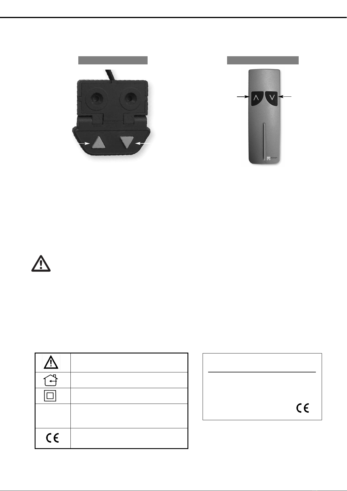
Press the “drive in” button. The telescopic drive drives into the bottom position. Release the button briefly (approx. 2-3 seconds)
and then press the “drive in” button for at least 6 seconds. During initialisation, the system will be lowered approximately 5 mm
and then raised again. This signalises the end of initialisation. Never release the “drive in” button during initialisation.
Fault Possible cause Checks
The system does not drive IIs the mains cable connected to the control
box?
Use a test lamp or similar device to check whether the
operating voltage in the mains connection is OK.
Are all plugs inserted correctly? Check all connections (refer to section 5)
Are any damages to the cables, manual
operating elements, control box, TV switch-
off or the telescopic drive visible
Damaged parts must be exchanged for original repla-
cement parts
The system stops when it is driven
out and can only be driven in
Is the system fully driven out? Once the system has reached the highest position it
can only be driven downwards
Is the system loaded above the maximum
stated load (refer to section 9)
Unload the system and try again
The max. drive out height is set using the
operating element – the system cannot be
driven higher using the remote control
Set to drive out height using the operating element –
refer to section 6
The system only drives downwards
at a low speed although it is not
overloaded.
nitialise the system - refer to section 10.1
The system cannot be driven using
the remote control
The system is driven to the lowest position
using the operating element
Set a different drive out height using the operating
element - refer to section 6
9. TECHNICAL DATA
Electrical
data
Mains voltage 230 V ~ 50-60 Hz
Input power 400 W
Output voltage 18 V
Operating mode nt. max 10 %, max. 2 min/18 min
Remote control frequency 433 MHz
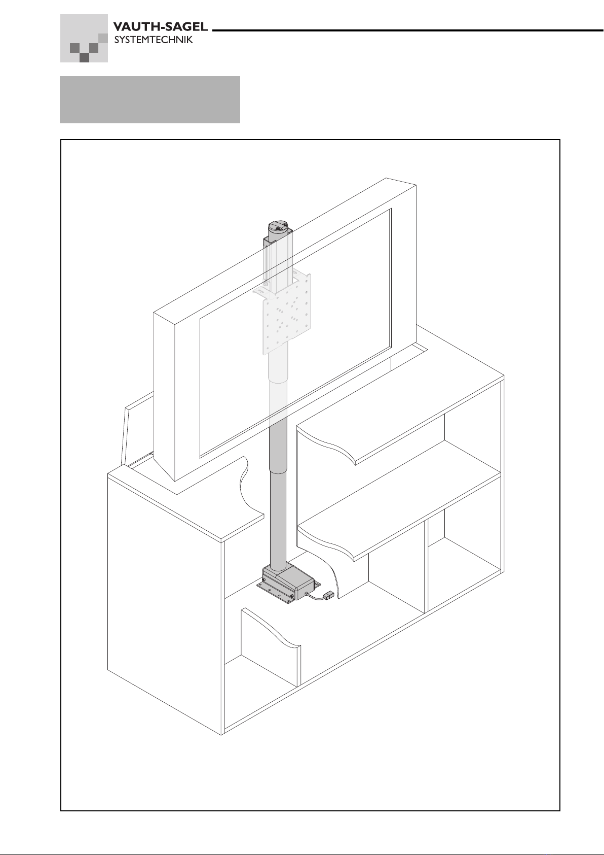
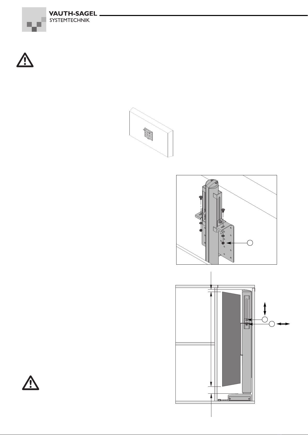
System data Installation height 847mm +5/-2mm (body construction with flap), 833mm +5/-2mm (body construction with
lid) (standard-setting)
Installation depth 195 mm (motor housing)
Width 245mm (retainer plate)
Hub 875 mm
Maximum screen height 765 mm
Maximum load 60 kg
Hub speed 45 mm/s
Environmental temperature +10°C to +40°C
creen fixings VESA 50, 75, 100, 200 mm (VESA = fixing standards for LCD and plasma screens e.g.
for VESA 50 the clearance between the vertical and horizontal fixing holes is 50 mm.

11
11 CLEANING AND MAINTENANCE
Before checking or cleaning the system, disconnect it from the mains by removing the mains plug from the socket.
Check all connections, cables, plugs and housing for damages and splits at regular intervals.
Remove dust and dirt from outside the system with a moist cloth at regular intervals.
12 DISPOSAL
This product may never be disposed of with household waste.
The disposal of recycling of the product must be carried out in accordance with national and local regulations!
13. MATERIAL DEFECTS LIABILIT AND PRODUCT LIABILIT
¤The manufacturer is not liable for damages which occur due to incorrect treatment, wear and tear, maintenance or other
actions.
¤The legal claim for material defects liability expires one year after transfer of the goods. This does not represent a durability
guarantee.
¤The customer is obliged to comply with the inspection obligations in accordance with §377 HGB (code of commercial law)
even if the goods are sold on.
¤The manufacturer reserves the right to choose between improving and resupplying the goods.
¤The expenses required for supplementary performance will not be covered by the manufacturer if these expenses increase
due to the goods being brought to a location other than the customer’s commercial location. This does not apply if the goods
are taken in relation to the intended use of the object.
¤Right of recourse by the customer against the manufacturer due to material defects liability claims which the customer
encounters from buyers is excluded if the customer has not complied with the inspection obligation and obligation to give
notice of defects.
¤The customer may only resell the goods for the intended purpose and must ensure that these goods are only sold to per-
sons who are aware of the product dangers and risks.
¤Liability by the manufacturer in accordance with legal regulations for replacement of damages is unrestricted if a breach of
obligations attributable to the manufacturer is intentional or caused by gross negligence. f a breach of obligations attributa-
ble to the manufacturer is based on simple negligence or if an essential contract obligation is culpably violated, damage
replacement liability is restricted to the foreseeable damages which typically occur in similar cases. Liability is excluded in all
other cases.
¤Liability according to the regulations of the product liability laws remains unaffected. Liability for death, physical damages
and damages to also remains unaffected.
We reserve the right to make technical changes to support progression.
The textual description and illustrations do not necessarily correspond with the scope of the delivery or any orders for replace-
ment parts. Sketches, diagrams and illustrative drawings are not to scale.
Publisher:
Vauth-Sagel Systemtechnik GmbH & Co. · Neue Straße 27 · D-33034 Brakel-Erkeln · Tel. +49 (0) 5272 601-01 · Fax +49 (0) 5272 601-193
Reproduction, including extracts, is only permitted with previous authorisation from the publisher
All rights are reserved.
Table of contents
Popular TV Mount manuals by other brands

FONESTAR
FONESTAR STV-651N instruction manual

REP Design
REP Design AMB-BKT-3T installation instructions

Kohler
Kohler 9038 installation instructions

Extron electronics
Extron electronics Mud Ring MR D Series installation guide

arkitect
arkitect ASTVMA14X instruction manual

peerless-AV
peerless-AV SmartMount SA735P Installation and assembly

Omnimount
Omnimount Silhouette 65 instruction manual

Premier Mounts
Premier Mounts INW-42 installation manual

Panasonic
Panasonic TY-WK23LR2W Service manual

Screen Innovations
Screen Innovations Jopplin installation instructions

Mounting Dream
Mounting Dream MD5231 installation instructions

KLING & FREITAG
KLING & FREITAG PASSIO user manual