Doc. No.: TT5 User’s Manual
Date: 05.06.2020
This design is the property of VECTRONIC Aerospace GmbH. Unauthorized duplication or distribution to a third party is prohibited.
4 /10
1Table of Contents
1The Transmitter...................................................................................................................5
2Mounting Instructions.........................................................................................................6
2.1 Connecting the trap ................................................................................................................. 6
2.2 Positioning of the transmitter .................................................................................................. 7
2.3 Resetting the trap..................................................................................................................... 7
3Operation.............................................................................................................................8
3.1 Standby Mode.......................................................................................................................... 8
3.2 Normal Mode .......................................................................................................................... 8
3.3 Alarm Mode ............................................................................................................................ 8
4Status Messages ..................................................................................................................9
5Lifetime calculation ..........................................................................................................10
Table of Figures
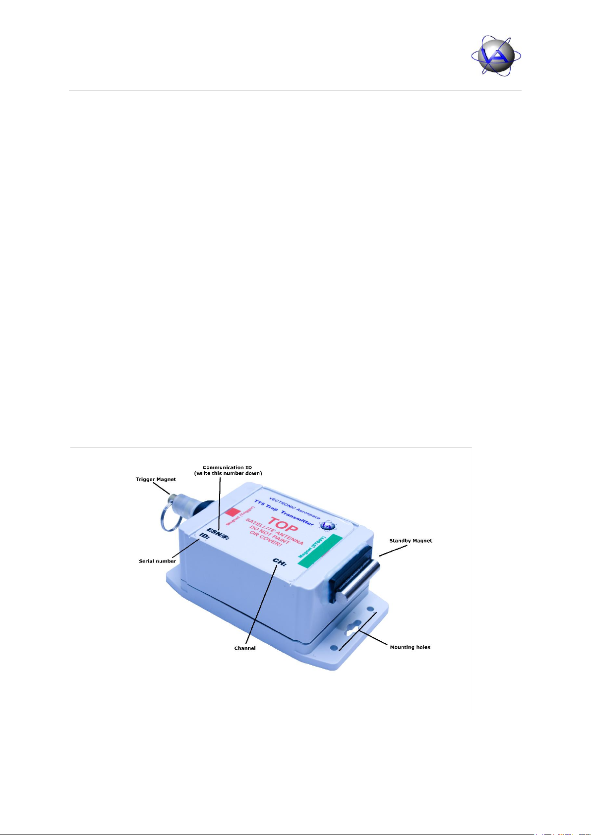
Figure 1: TT5 Trap Transmitter in Stand-by mode....................................................................5
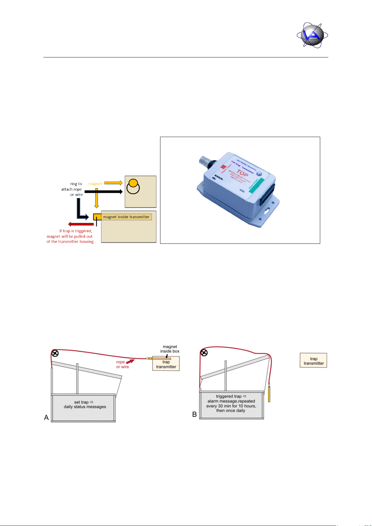
Figure 2: Left: The elongated magnet is inserted into the transmitter box and can be attached
to the trap by a rope or wire. If the trap is triggered, the magnet has to be pulled
out of the box by the rope to set off an alarm. Right: Triggered trap transmitter,
elongated magnet is removed from transmitter box.................................................6
Figure 3: Example for triggering the trap: A) The trap is connected to the transmitter’s magnet
by a rope or wire. B) When the trap is triggered, the rope/wire pulls the magnet out
of the transmitter box. The transmitter sends an alarm message every 30 minutes
for 10 hours. After that you will receive one Email per day....................................6
Figure 4: Trigger Magnet...........................................................................................................7
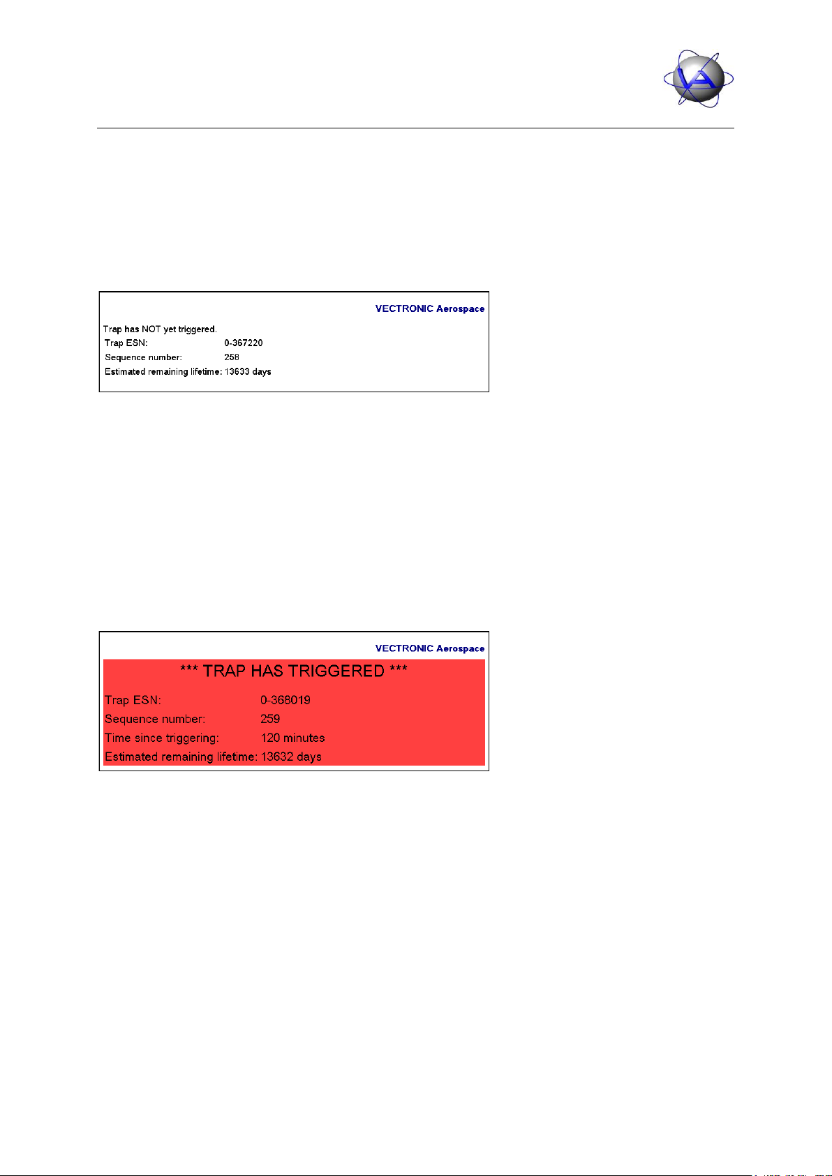
Figure 5: Status email in HTML ................................................................................................9
Figure 6: Alarm email ................................................................................................................9