Gira 5331 Series User manual

Wireless wall transmitter, 1-gang with inscription space
Order No. : 5331..
Wireless wall transmitter, 3-gang with inscription space
Order No. : 5333 ..
Operating instructions
1 Safety instructions
Electrical devices may only be mounted and connected by electrically skilled
persons.
Serious injuries, fire or property damage possible. Please read and follow manual fully.
Keep button cells out of reach of children! If button cells are swallowed, get medical help
immediately.
Risk of explosion! Do not throw batteries into fire.
Risk of explosion! Do not recharge batteries.
The radio communication takes place via a non-exclusively available transmission path,
and is therefore not suitable for safety-related applications, such as emergency stop and
emergency call.
These instructions are an integral part of the product, and must remain with the end
customer.
2 Device components
Figure 1: Radio wall transmitter
(1) Radio wall transmitter
(2) Button Prog, covered
(3) Button covers
3 Function
Intended use
- Radio sensor for transmission of switching, dimming, blind movement and scene
commands
- Operation with radio actuators from the eNet system
1/10
32579222 24.04.2017
Wireless wall transmitter, 1-gang with inscription space, Wireless wall
transmitter, 3-gang with inscription space
10864957

Product characteristics
- Two adjacent buttons each belong to one channel
- Two-coloured LEDs to the right and left of the buttons for signalling
- The switch-on brightness in combination with dimmer actuators can be saved.
- Battery-powered device
- Signalling of transmission errors can be switched off
- Scenes, radio wall transmitter, 1-gang: All Off, one individual scene
- Scenes, radio wall transmitter, 3-gang: All Off, five individual scenes
Can be set with eNet server:
- Scene All On
- Operation locks
Supplementary functions with eNet Server
- Fully encrypted radio transmission (AES-CCM) from eNet Server software version 2.0
- Update of the device software
- Reading of error memory
4 Operation
iWhen operating with the eNet Server, operation and signalling could vary from what is
described here.
Function of status LED in operation
As soon as a button is pressed or released, the corresponding status LED first signals radio
communication
- The status LED lights up red for 3 seconds
and then the actuator status/group status on operation with channel buttons
- Left status LED turns green for 3 seconds:
At least one actuator is switched on, or one Venetian blind is not in the top end position
- Right status LED turns green for 3 seconds:
All the actuators are switched off or the blinds are all in the upper end position
or the actuator status/group status on operation with scene buttons
- Status LED turns green for 3 seconds:
At least one actuator is switched on, or one Venetian blind is not in the top end position
- Status LED remains off:
All the actuators are switched off or the blinds are all in the upper end position
iIf there is no status message from at least one actuator, a transmission error is signaled.
Status LED flashes red quickly for 5 seconds.
32579222 10864957 24.04.2017 2/10
Wireless wall transmitter, 1-gang with inscription space, Wireless wall
transmitter, 3-gang with inscription space
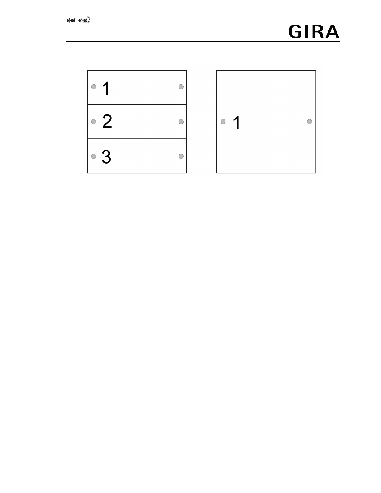
Channel assignment of the wall transmitter
Figure 2: Channel assignment for operation
Operating light
oSwitching: Press button for less than 0.4 seconds.
oDimming: Press the button for longer than 0.4 seconds. The dimming process ends when
the button is released.
oSwitching on dimmer actuators at minimum brightness: Press the right button for longer
than 0.4 seconds.
oSwitching on dimmer actuators at minimum brightness and dimming to maximum
brightness: Press the left button for longer than 0.4 seconds.
Operating blind
oMoving the Venetian blind: Press the button for longer than 1 second.
oStopping or adjusting the Venetian blind: Press the button for less than 1 second.
Operating push-button actuator
oPress the button. The load is switched on for the duration of the button-press.
iThe maximum actuation length is 60 seconds.
Recalling scenes
oPress the scene button briefly.
Actuators switching to the saved scene.
Changing scene
oPress the scene button briefly.
Actuators switching to the saved scene.
oSetting a new scene.
oPress scene button for longer than 4 seconds.
Actuators first switching to the old scene and save the new scene after 4 seconds.
Save switch-on brightness
With dimmer actuators a brightness value can be saved to which the dimmer actuator switches
after a short button press.
The buttons of a channel are set as channel buttons.
oSet required switch-on brightness.
32579222 10864957 24.04.2017 3/10
Wireless wall transmitter, 1-gang with inscription space, Wireless wall
transmitter, 3-gang with inscription space

oPress both buttons of a channel simultaneously for longer than 4 seconds.
The light is briefly switched off and switched on again to the switch-on brightness. Switch-
on brightness is saved.
Polling sum status
The buttons of a channel are set as channel buttons.
oPress both buttons of a channel simultaneously for 1 to 4 seconds.
Signalling of radio transmission and group status (see function of the status LED in
operation)
5 Information for electrically skilled persons
5.1 Fitting and electrical connection
Connecting and fitting the device
To ensure good transmission quality, keep a sufficient distance from any possible sources of
interference, e.g. metallic surfaces, microwave ovens, hi-fi and TV systems, ballasts or
transformers.
iPerform commissioning procedures before installation (see chapter Commissioning).
iMount the wall transmitter in the correct position, button Prog (2) at bottom.
Screw mounting
Figure 3: Screw mounting
oUsing a screwdriver, carefully remove the button covers (3).
oInsert supplied threaded sleeves (5) through the screw holes from the rear.
oMount the wall transmitter (1) and frame (6) directly to the wall using the screws (7) and
anchors (4).
oAttach the button covers.
Glue mounting
In order to glue the wall transmitter directly to an even surface, e.g. glass, a base plate is
available (see accessories).
32579222 10864957 24.04.2017 4/10
Wireless wall transmitter, 1-gang with inscription space, Wireless wall
transmitter, 3-gang with inscription space

Figure 4: Glue mounting
iFor multiple combinations with glue mounting, the edge pieces (8) of neighbouring base
plates have to be broken off at the predetermined breaking points.
To ensure good adhesion, the substrate must be flat and free of dust and grease.
oGlue the base plate (9) (see Accessories chapter) directly to the surface.
oUsing a screwdriver, carefully remove the button covers (3).
oFix the wall transmitter (1) and frame (6) with the screws (10).
oAttach the button covers.
Installation in appliance box
Figure 5: Installation in appliance box
oUse screws to fasten the supporting frame (11) (see Chapter 'Accessories') to the
appliance box.
oUsing a screwdriver, carefully remove the button covers (3).
oUse screws (12) to mount the wall transmitter (1) and frame (6) to the supporting frame).
oAttach the button covers.
32579222 10864957 24.04.2017 5/10
Wireless wall transmitter, 1-gang with inscription space, Wireless wall
transmitter, 3-gang with inscription space
5.2 Commissioning
DANGER!
Electrical shock when live parts are touched.
Electrical shocks can be fatal.
During commissioning, cover the parts carrying voltage on radio transmitters
and actuators and in their surrounding area.
Insert battery
WARNING!
Risk of chemical burns.
Batteries can burst and leak.
Replace batteries only with an identical or equivalent type.
The battery holder is located on the rear side.
oUsing a screwdriver, carefully remove the button covers and unscrew the device.
iKeep contacts of batteries and device free of grease.
oApply battery to the positive contact of the battery holder. Observe polarity: the positive
pole of the battery must be at the top.
oPress gently on battery to snap it in.
The wall transmitter is ready for operation.
Configuring the buttons
In the as-delivered state, all the buttons are configured as channel buttons.
oUsing a screwdriver, carefully remove operating rockers.
oPress the Prog (Figure 1) button for approx. 1 second.
The left-hand status LEDs of the channels turn green. The wall transmitter is in
configuration mode for 3 seconds.
oSetting as channel buttons: Press the left button of the appropriate channel until the status
LED turns green.
The right and left button of the channel are set as channel buttons.
oSetting as scene button: Press the right button of the appropriate channel until the right
status LED turns green.
The right and left button of the channel are set as scene buttons.
Overview of scene buttons
Buttons Button allocation
1 left / 1 right Scene 1 / All Off
2 left / 2 right Scenes 2 / Scene 3
3 left / 3 right Scenes 4 / Scene 5
iButtons 2 and 3 only for 3-gang wall transmitters
Connecting to radio actuator
iUp to 10 radio actuators can be connected to a transmitter in a single step.
oSwitch the actuator to programming mode (see actuator instructions).
oPress the Prog button for longer than 4 seconds.
Status LEDs flash red. The wall transmitter is in programming mode for approx. 1 minute.
oPress the right or left button of the required channel or the scene button briefly
32579222 10864957 24.04.2017 6/10
Wireless wall transmitter, 1-gang with inscription space, Wireless wall
transmitter, 3-gang with inscription space

The appropriate status LED lights up for approx. 5 seconds, and the channel buttons or
scene button are connected to the actuator. The wall transmitter and actuator exit the
programming mode automatically.
iIf the appropriate status LED of the radio transmitter flashes 3 times at 1-second intervals
for approx. 5 seconds, then the programming operation was not successful. The actuator is
outside radio range, not in programming mode or there are radio faults.
iIf the status LED of the actuator flashes 3 times at 1-second intervals for approx. 5
seconds, then the programming operation was not successful. All the memory locations in
the actuator or radio transmitter are occupied.
iThe All Off button is connected to the actuator automatically as soon as the first connection
to a radio transmitter takes place. Scene buttons must be connected separately.
iPress the Prog button once again for longer than 4 seconds to terminate the programming
mode earlier.
Polling button programming
oPress the PROG button for approx. 1 second.
All functions are terminated.
The left-hand Status LED turns green on programming as channel buttons.
The right-hand Status LED turns green on programming as scene buttons.
Disconnecting connection to an actuator
oCarry out the same steps as when connecting (see the chapter Connecting to radio
actuator).
The status LED of the actuator flashes quickly for 5 seconds. The actuator is disconnected
from the radio transmitter. The actuator and radio transmitter exit the programming mode
automatically.
iIf there several connections or scene buttons for an actuator, all the connections must be
disconnected individually.
iAll On and All Off buttons of a radio transmitter are disconnected automatically as soon as
the last connection to the actuator is disconnected. Manual disconnection is not possible.
Resetting the channel or scene button
All the connections of the channel buttons or the scene button to actuators are disconnected
and parameters are reset to default setting.
iThe connections in the actuators are preserved and must be deleted separately.
oPress the Prog button for longer than 20 seconds.
The status LEDs flash red after 4 seconds. The status LEDs flash more quickly after
20 seconds.
oRelease the Prog button and press briefly a channel button of the appropriate channel or
the scene button once again within 10 seconds.
The appropriate status LED flashes more slowly for approx. 5 seconds.
The channel buttons or the scene button has been reset. The setting as channel buttons or
scene button is retained.
Resetting wall transmitter to the default setting
All connections to actuators are disconnected and parameters are reset to default setting.
iThe connections in the actuators are preserved and must be deleted separately.
iIn the case of channel buttons, signalling only takes place using the right-hand LED and, in
the case of scene buttons, using the left and right-hand LEDs.
oPress the Prog button for longer than 20 seconds.
The status LEDs flash red after 4 seconds. The status LEDs flash more quickly after
20 seconds.
oRelease Prog button and press briefly once again within 10 seconds.
The status LED flashes more slowly for approx. 5 seconds.
32579222 10864957 24.04.2017 7/10
Wireless wall transmitter, 1-gang with inscription space, Wireless wall
transmitter, 3-gang with inscription space
The wall transmitter is reset to default setting. All the buttons are set as channel buttons.
6 Appendix
Remove empty batteries immediately and dispose of in an environmentally friendly
manner. Do not throw batteries into household waste. Consult your local authorities
about environmentally friendly disposal. According to statutory provisions, the end
consumer is obligated to return used batteries.
6.1 Technical data
Rated voltage DC 3V
Battery type 1×Lithium CR 2450N
Ambient temperature -5 ... +45°C
Degree of protection IP 20
Transmitting range in free field typ. 100m
Radio frequency 868.0 ... 868.6MHz
Transmission capacity max. 20mW
Receiver category 2
6.2 Parameter list
The device parameters can be changed with the eNet server:
Device configuration
Parameter name Setting options, Basic
setting
Explanations
Function Rocker, Other modes, Unused
Basic setting: Rocker
Rocker
The channel works as a
channel button. Setting is
always made in pairs.
Other modes
The channel works as a scene
button. Setting is always made
in pairs.
Unused
The channel is not displayed
in the eNet SMART HOME
app and is disabled for use in
the commissioning interface.
Operating mode App use, lock-out protection,
forced operation, wind alarm,
sun protection, twilight
Basic setting: App use
Setting the type of scene used
for a scene button. Setting is
always made in pairs.
Advanced settings
Parameter name Setting options, Basic
setting
Explanations
Manual commissioning On, Off
Basic setting: On
Disables manual
commissioning for all device
channels.
Note: In the "Off" setting, the
device cannot be reset to the
factory setting.
Extended channel settings
Parameter name Setting options, Basic
setting
Explanations
32579222 10864957 24.04.2017 8/10
Wireless wall transmitter, 1-gang with inscription space, Wireless wall
transmitter, 3-gang with inscription space

Manual commissioning On, Off
Basic setting: On
Blocks manual commissioning
for the device channel.
Note: In the "Off" setting, the
device cannot be reset to the
factory setting.
Local Operation On, Off
Basic setting: On
Blocks the device channel for
local operation.
6.3 Troubleshooting
After a button actuation, the status LED of the channel or scene button flashes red
slowly for 3 seconds.
Cause: battery in the wall transmitter is almost empty.
Changing the battery (see chapter Commissioning – Inserting the battery).
The receiver does not react and the status LED of the channel or scene button displays a
transmission error. Status LED flashes red quickly for 3 seconds.
Cause 1: Radio range exceeded. Structural obstacles reduce the range.
Using a radio repeater.
Cause 2: Actuator is not ready for operation.
Check the actuator and mains voltage.
Cause 3: There are radio faults, e.g. through outside radio.
Eliminate radio interference.
iThe actuator causing the transmission error can be removed from the display of
transmission errors. To do this, briefly press the Prog button of the wall transmitter during
signalling. The status LED lights up red. During this time, do not press any button on the
wall transmitter. The actuator is automatically taken into account again when it transmits a
status message after radio transmission.
After a button has been pressed, the status LED flashes red quickly for 3 seconds.
Cause: Maximum permitted transmission period (statutory Duty Cycle Limit) has almost been
reached. For the function of the transmitter to continue, the polling and display of the sum status
will be switched off. As soon as sufficient transmission time is available again, the sum status
will again be polled on button actuation.
Actuate the transmitter again after a short waiting time, normally a few seconds.
Reduce the number of actuations.
Reduce the number of actuators connected to the transmitter.
6.4 Accessories
Mounting plate set Order No. 5339 00
Support ring, plastic Order No. 5338 00
6.5 Conformity
Gira Giersiepen GmbH & Co. KG hereby declares that the radio system type
Order No. 5331.. / 5333 ..
corresponds to the directive 2014/53/EU. You can find the full article number on the device. The
complete text of the EU Declaration of Conformity is available under the Internet address:
www.gira.de/konformitaet
6.6 Warranty
The warranty follows about the specialty store in between the legal framework as provided for
by law
Please submit or send faulty devices postage paid together with an error description to your
responsible salesperson (specialist trade/installation company/electrical specialist trade). They
will forward the devices to the Gira Service Center.
32579222 10864957 24.04.2017 9/10
Wireless wall transmitter, 1-gang with inscription space, Wireless wall
transmitter, 3-gang with inscription space

Gira
Giersiepen GmbH & Co. KG
Elektro-Installations-
Systeme
Industriegebiet Mermbach
Dahlienstraße
42477 Radevormwald
Postfach 12 20
42461 Radevormwald
Deutschland
Tel +49(0)21 95 - 602-0
Fax +49(0)21 95 - 602-191
www.gira.de
32579222 10864957 24.04.2017 10/10
Wireless wall transmitter, 1-gang with inscription space, Wireless wall
transmitter, 3-gang with inscription space
Other manuals for 5331 Series
1
This manual suits for next models
1
Table of contents
Other Gira Transmitter manuals


