Vectronic Aerospace Drop-Off Release User manual

Project:
Drop-Off Release
Transmitter
Title:
User's Manual
Document No.: Drop-off User’s Manual
Version: 1.4

Doc. No.: Release Transmitter User Manual
Date: 02.07.2019
2
Design is the property of VECTRONIC Aerospace GmbH.
Unauthorized duplication or distribution to a third party is prohibited.
Name
Date
Signature
Prepared by
Annette Krop-
Benesch
23.12.2010
Edited by
Marc Büntjen
12.06.2014
Edited by
Chris Samek
02.07.2019
Checked by
Approved by
Authorised
by

Doc. No.: Release Transmitter User Manual
Date: 02.07.2019
3
Design is the property of VECTRONIC Aerospace GmbH.
Unauthorized duplication or distribution to a third party is prohibited.
DOCUMENT CHANGE RECORD
Issue
Date
Item(s) Affected
Description
1
23.12.2010
-
Initial Issue
2
01.02.2011
Installation
Automatic installation of program and
driver
3
31.03.2011
Battery Charger
Addition LCD Battery Charger
4
02.07.2019
2;3;6;7;8;9
Grammar

Doc. No.: Release Transmitter User Manual
Date: 02.07.2019
4
Design is the property of VECTRONIC Aerospace GmbH.
Unauthorized duplication or distribution to a third party is prohibited.
Table of Contents
1Product Overview................................................................................................. 5
2The Release Transmitter...................................................................................... 6
3Quick guide to the keyboard ................................................................................ 7
4Quick guide to the Release Transmitter............................................................... 8
5Charging batteries and inserting them into the transmitter................................... 8
6Connecting the Transmitter to the PC................................................................ 10
7Drop-off list......................................................................................................... 11
8Configuring drop-offs or upload new firmware ................................................... 11
9Releasing a radio drop-off.................................................................................. 11
10 The information menu..................................................................................... 12
11 The UHF ID-tag receiver................................................................................. 12
12 Operating instructions for Sanyo AA/AAA USB Charger ................................ 14
13 Operating instructions for VARTA LCD Charger 57070.................................. 15
14 Manual installation of the Release Transmitter driver..................................... 17

Doc. No.: Release Transmitter User Manual
Date: 02.07.2019
5
Design is the property of VECTRONIC Aerospace GmbH.
Unauthorized duplication or distribution to a third party is prohibited.
1 Product Overview
The Drop-off Release Transmitter enables you to communicate with VECTRONIC
drop-offs and receive UHF ID-tag numbers. Its functions are:
•while the release transmitter is connected to the PC via USB cable, it transfers
drop-off telemetry data to the computer and sends release times and firmware to
the drop-off. Communication is managed with the GPS PLUS Drop-Off Manager
software
•radio-and-timer-controlled drop-off can be released on demand within a range of
500 m by sending the release command from the transmitter
•the release transmitter is able to receive the IDs of VECTRONIC UHF-tags used
for the proximity sensor.

Doc. No.: Release Transmitter User Manual
Date: 02.07.2019
6
Design is the property of VECTRONIC Aerospace GmbH.
Unauthorized duplication or distribution to a third party is prohibited.
2 The Release Transmitter
The release transmitter is switched on with the button. It will switch off automatically
30 seconds after the last button has been pressed.
The release transmitter can be connected to a PC for configuration with an USB cable.
The display willthen show USB PC . The keys will not respond while the transmitter
is attached to a PC via USB. After 30 seconds, the backlight of the display will be
switched off; after 5 minutes, the transmitter will be switched off. It can be switched on
again by pressing the button.
Figure 1: Left: Release Transmitter, right top: VECTRONIC
UHF 2-Element Yagi Antenna, right: waterproof USB-connector with rubber cover as protection
against dirt.
Note: Never use the transmitter without, or with a wrong, antenna! Use only the
VECTRONIC 2-Element Yagi which came with the Release Transmitter unit or an
approved substitute. Otherwise you may severely damage the transmitter.
Note: In the field, make sure the USB port is always protected by the rubber cover to
avoid dirt entering the port.

Doc. No.: Release Transmitter User Manual
Date: 02.07.2019
7
Design is the property of VECTRONIC Aerospace GmbH.
Unauthorized duplication or distribution to a third party is prohibited.
3 Quick guide to the keyboard
The keyboard is designed to give you easy access to the features of the transmitter.
The keys will not respond when the transmitter is attached to a PC via USB.
Press briefly to switch on the transmitter. The transmitter will
automatically give a list of all registered drop-offs. Press this button at
any point in the menus to reset the transmitter and return to the drop-off
list.
Allows you to move up in the drop-off list or the menus
Allows you to move down in the drop-off list or the menus
Triggers the release of a radio drop-off
Opens the transmitter information menu showing battery voltage,
hardware version, software version, and serial number of handheld
Activates the UHF ID-tag receiver
Exits the menu or ID receiver and cancels the fire command
Confirms the fire command

Doc. No.: Release Transmitter User Manual
Date: 02.07.2019
8
Design is the property of VECTRONIC Aerospace GmbH.
Unauthorized duplication or distribution to a third party is prohibited.
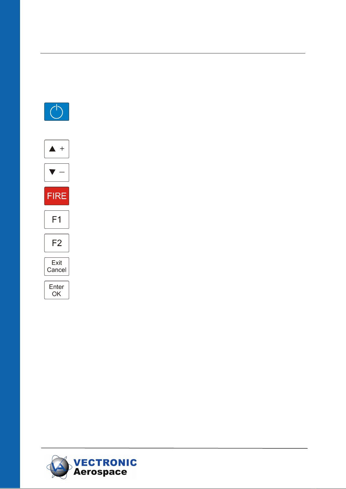
4 Quick guide to the Release Transmitter
1. Charge the Eneloop™ batteries with the Sanyo USB battery charger and insert
them into the transmitter (s. section 5)
2. Connect the Release Transmitter to the PC via USB cable (s. section 0)
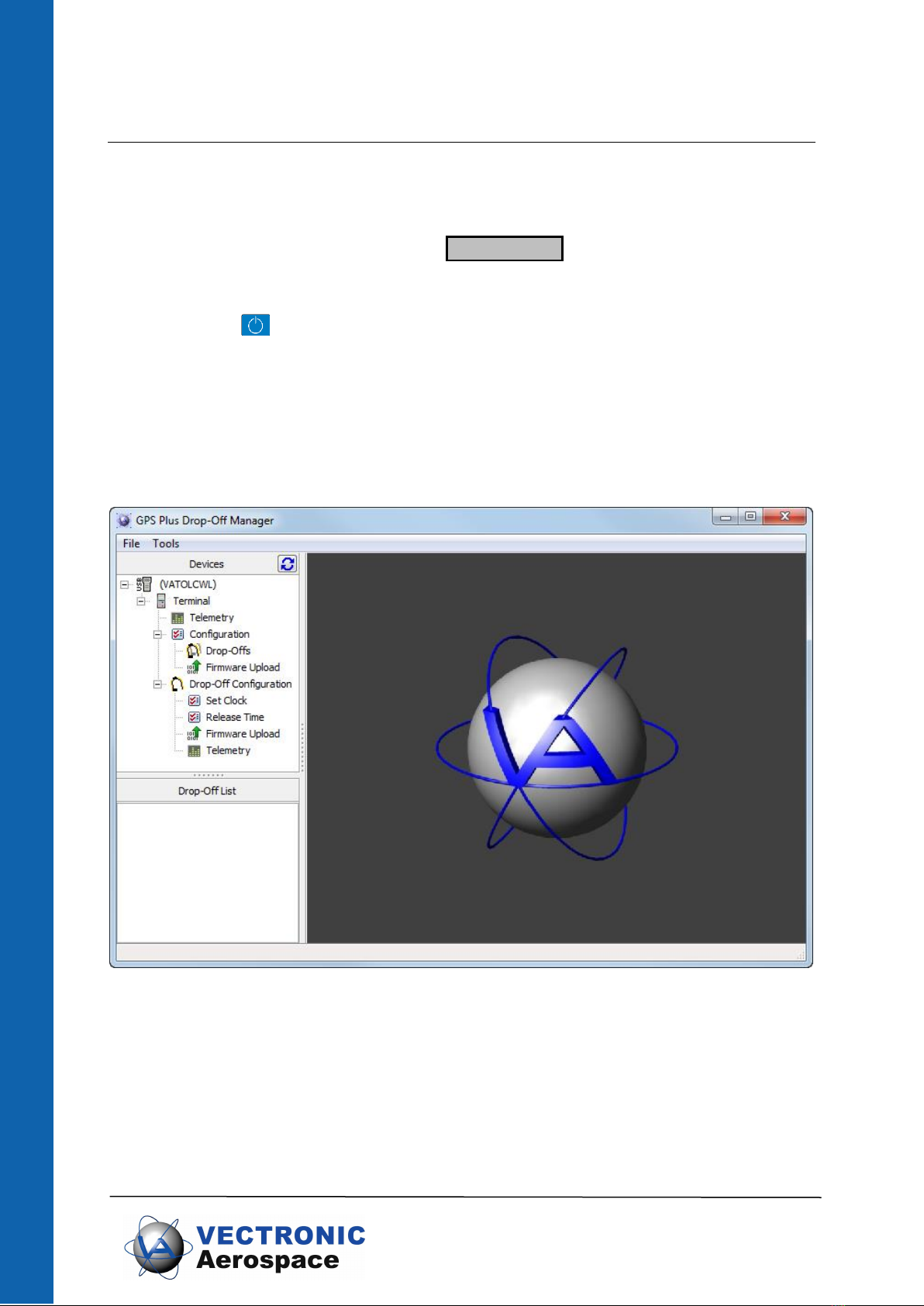
3. Start the GPS PLUS Drop-Off Manager; it will automatically recognise the
Release Transmitter.
4. Register the drop-offs on the transmitter. To do this, the drop-off first must be
registered in the GPS PLUS Drop-Off Manager version you are using (refer to
GPS PLUS Drop-Off Manager manual). Then you can register the drop-off on
the transmitter.
5. You are now able to communicate with the drop-off and release it on demand if
it is a radio drop-off.
6. To release a radio-drop off, refer to section 9.
5 Charging batteries and inserting them into the transmitter
Before you are able to use the Release Transmitter, the included Eneloop™ batteries
need to be charged. For this, use the included Sanyo USB battery charger only (for
further details see Sanyo manual page 18). You can charge two batteries at the same
time. Recharging time is approximately 5 hours. Raise the adjuster and insert the
batteries into the charger. Then connect the charger’s USB plug to a USB port at your
PC.
Note: Make sure that no other equipment is connected to any other USB port or the
required power might be exceeded. Charging might be stopped, the computer might
be damaged, or data might be lost.
While recharging, the LED charge indicator is flashing. When charging has been
completed, the LED remains lit. Remove the USB connector from the USB port, then
remove the batteries from the charger. They will be hot immediately after recharging.
Repeat the process with the second pair of batteries. For storage, lower the adjuster.
Note: Do not use the charger for any other batteries than Eneloop™.
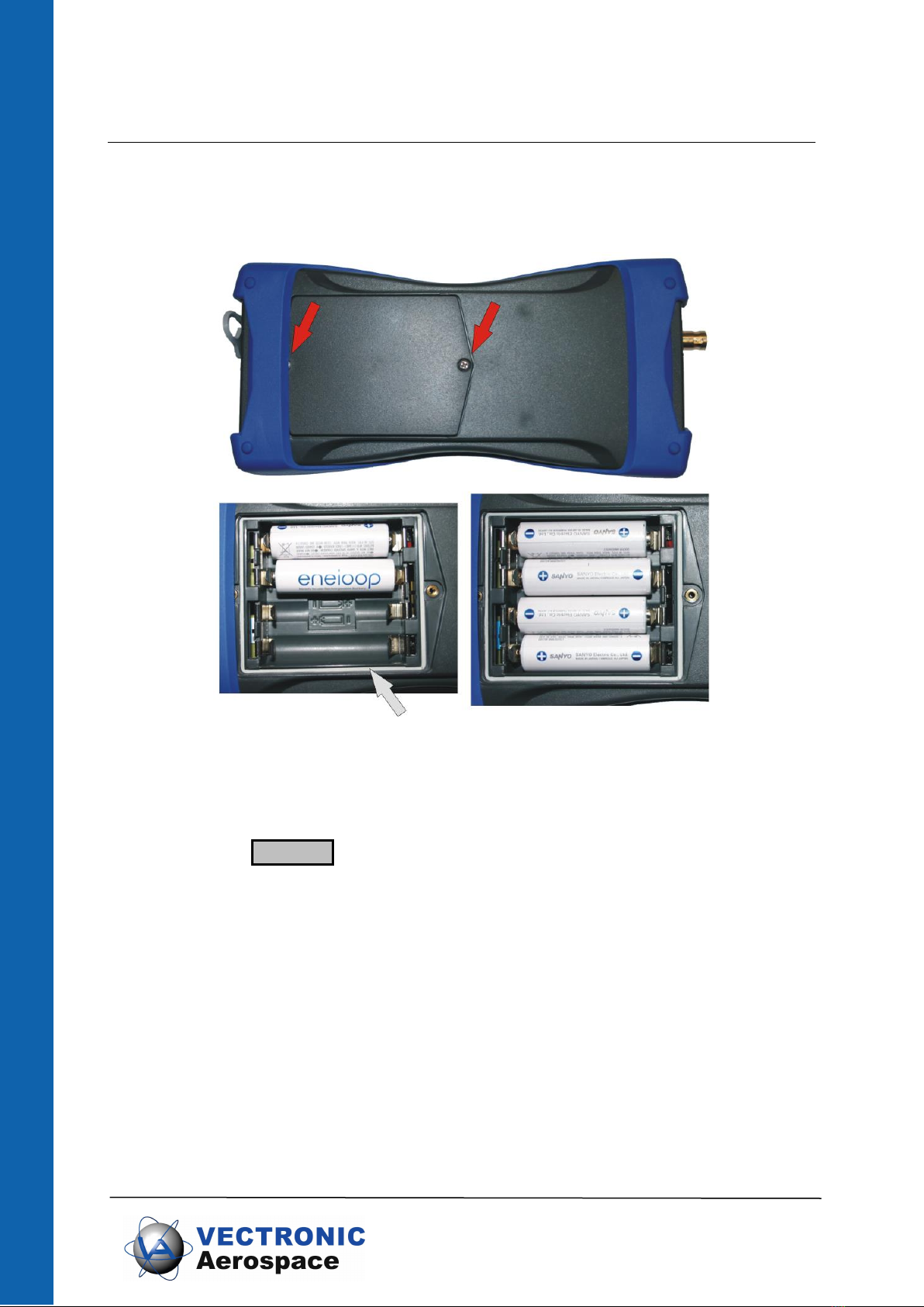
Open the transmitter by unscrewing the two screws on the back (see Figure 2, red
arrows). Be careful not to damage the waterproof seal (see Figure 2, grey arrows).
Carefully insert the batteries with the correct polarity (for details refer to picture in
battery compartment and Figure 2).

Doc. No.: Release Transmitter User Manual
Date: 02.07.2019
9
Design is the property of VECTRONIC Aerospace GmbH.
Unauthorized duplication or distribution to a third party is prohibited.
To remove batteries from the compartment, knock the transmitter against your hand
and thus loosen the batteries. Do not insert objects (e.g. screw drivers) into the
compartment to force the batteries out.
Figure 2: Back of Release Transmitter; red arrows indicate the screws for opening the battery
hatch, grey arrow indicates the waterproof seal. Make sure the batteries are inserted with the
correct polarity.
Battery voltage of the release transmitter must not fall under 4.0 Volt. At 4.05 Volt, the
display will warn LowBat. for a few seconds and switch off the backlight. At a lower
voltage, the transmitter cannot be switched on anymore. Please recharge batteries
with the associated Sanyo battery charger only.
The rechargeable Eneloop™ batteries delivered with the transmitter do discharge very
slowly. Do not to exchange them for other batteries, since these might lose voltage
during storage and might not be able to provide enough power to release the collar on
demand. However, if in urgent cases you need to exchange the batteries, and you do
not have an additional set of Eneloop™ batteries, you can use High Power Alkaline
batteries (Do not recharge these! Danger of explosion!), NiCd rechargeable batteries,
or NiMH rechargeable batteries with current rating > 1A.

Doc. No.: Release Transmitter User Manual
Date: 02.07.2019
10
Design is the property of VECTRONIC Aerospace GmbH.
Unauthorized duplication or distribution to a third party is prohibited.
6 Connecting the Transmitter to the PC
Easily connect the transmitter to a PC via USB cable. The transmitter is switched on
automatically and the display will show USB PC . Thirty seconds after the last
communication between PC and transmitter took place, the display backlight will be
switched off. After5 minutes, the transmitter isswitched off. It can beswitched on again
by pressing the button.
If the transmitter is connected via USB, it is supplied exclusively by the USB port; the
output power is limited to 2 mW.
The Release Transmitter is operated with the GPS PLUS Drop-Off Manager. When a
transmitter is connected to the PC, it will be displayed in the upper left section of the
program (“Devices”).
Figure 3: Opening window of the GPS Plus Drop Off Manager with release transmitter connected
to PC

Doc. No.: Release Transmitter User Manual
Date: 02.07.2019
11
Design is the property of VECTRONIC Aerospace GmbH.
Unauthorized duplication or distribution to a third party is prohibited.
For using the software, please refer to the GPS PLUS Drop-Off Manager manual. You
need to connect the transmitter to a PC for the following tasks:
•to register a drop-off on the transmitter; this is necessary to enable
communication with this drop-off
•to change configuration of a drop-off
•to upload new firmware to the drop-off
If you use the transmitter as interface between PC and drop-off, the drop-off needs to
be within a few meters of the transmitter and you must be able to detach and attach
the magnet to the drop-off.
7 Drop-off list
When you switch on the transmitter, it will automatically give a list of all drop-offs
registered on the transmitter. The drop-off with the lowest number will be displayed
first. Move upwards and downwards this list with the Up and Down buttons.
8 Configuring drop-offs or upload new firmware
To configure a drop off, to change the release settings, or to upload new firmware, the
transmitter needs to be connected to the PC with the GPS PLUS Drop-Off Manager
program opened. For details please refer to the GPS PLUS Drop-Off Manager manual.
9 Releasing a radio drop-off
The main feature of the release transmitter is to release a radio-and-timer-controlled
drop-off on demand. The maximum range for this is 500 m. If possible, release the
drop-off while you can see the animal.
Note: Prior to preparing the drop-off release make sure the transmitter battery’s
voltage is higher than 4.05 Volt. Otherwise there might not be enough power to
reach the drop-off. Ideally, the battery voltage would be close to 5.0 Volt.
Note: Connect the correct antenna to the device. A wrong or missing
antenna can damage the device as the strong signal can’t be transmitted
but discharges internally!
Note: It is possible that the animal will be startled when the collar is released
and drops down. Avoid triggering the drop-off if the animal is in a situation
where it could get hurt by erratic movements (e.g. on a cliff edge).

Doc. No.: Release Transmitter User Manual
Date: 02.07.2019
12
Design is the property of VECTRONIC Aerospace GmbH.
Unauthorized duplication or distribution to a third party is prohibited.
To release a drop-off, switch on the transmitter. Scroll the drop-off list until you have
found the ID of the drop-off you want to release. Press the button 5 seconds until
Fire? is shown in the display. This is the last opportunity to abort the release. Press
Exit/Cancel to abort. Press Enter/OK within 5 seconds to transmit the release
command to the drop-off, otherwise the display will return to the ID list. If you press
Enter/OK , the displaywill switch to Transm. …. The transmitter now sends the signal
to the drop-off for 33 seconds. The only chance to abort the command in this stage is
to press the button, but it is possible that the drop-off will have already received
the command and releases anyway. After the command has reached the drop-off, it
takes about 25 seconds to completely release the collar.
Note: There will be no confirmation from the drop-off if the signal was received and the
drop-off triggered. If you are not sure whether the collar has been released, you can
resend the release command.
10 The information menu
With F1 , you can enter the information menu of the transmitter. If you press F1 , the
display will show Battery . Press Enter/OK to view the current battery voltage. Press
Exit/Cancel to return to the menu. With the Up and Down buttons, you can
scroll between the topics:
Battery Voltage of the transmitter battery
Hardware Version of the transmitter hardware
Software Version of the transmitter’s software
SerialNo Serial Number of the transmitter
While the battery voltage is necessary for you to know to ensure enough power for the
drop-off release, the other three topics are only of interest for diagnostics if there are
problems with the transmitter.
11 The UHF ID-tag receiver
The Release Transmitter can be used to check if VECTRONIC UHF ID-tags are in
range. To do this, press F2 . The display will switch to ID-Rec. . Press Enter/OK to
start searching for UHF-tags. The display will switch to ID. . While the transmitter
is receiving ID numbers of UHF-tags the dot will blink. The ID numbers of the received

Doc. No.: Release Transmitter User Manual
Date: 02.07.2019
13
Design is the property of VECTRONIC Aerospace GmbH.
Unauthorized duplication or distribution to a third party is prohibited.
tags will be shown in the display, e.g. ID.65534 . If more than one UHF-tag is in range,
the ID numbers will be shown alternately. Press Exit/Cancel to leave the ID-reception.

Doc. No.: Release Transmitter User Manual
Date: 02.07.2019
14
Design is the property of VECTRONIC Aerospace GmbH.
Unauthorized duplication or distribution to a third party is prohibited.
12 Operating instructions for Sanyo AA/AAA USB Charger

Doc. No.: Release Transmitter User Manual
Date: 02.07.2019
15
Design is the property of VECTRONIC Aerospace GmbH.
Unauthorized duplication or distribution to a third party is prohibited.
13 Operating instructions for VARTA LCD Charger 57070
➊Connect the charger with one of the three possible power
sources:
a) AC 100-240V by power adaptor
b) DC 12V by car cord
c) DC 5V (500mA) by USB cord
➋Power on but no batteries in the charger: VARTA logo as
power indicator.
➌Insert either 2 or 4 AA or AAA rechargeable batteries into
the battery compartment. The batteries must be loaded
in pairs and should therefore have similar charge status.
A mix of AA and AAA batteries is possible. Make sure
that the batteries are inserted according to the correct
polarity and that each battery is touching both contacts.
➍The actual charging level is indicated by up to three bars
per battery symbol. It will only take 10 seconds to do this
power check. The result will be displayed on the blue
LCD.
➎After starting the charging, a new bar fixes its position at
the filling of a further 1/3 capacity. Indication works as
follows
a) rolling bar(s) = charging
b) all three bars fixed = charging finished
c) empty battery symbol = no charge (error)
➏The charging time isabout 120mins (2 AA cells), 240mins
(4 AA cells) and 150mins (2 or 4 AAA cells) and depends
on the initial capacity and charging conditions.
➐Charging time with USB-In function is around 5 hours for
2 and around 10 hours for 4 batteries.
➑The automatic charging control function prevents the
batteries from being overcharged. The battery
performance is maintained by trickle charge.

Doc. No.: Release Transmitter User Manual
Date: 02.07.2019
16
Design is the property of VECTRONIC Aerospace GmbH.
Unauthorized duplication or distribution to a third party is prohibited.
This battery charger is designed for use anywhere in the world (100-240V, 50-60Hz).
If necessary, you may however need an adapter for the respective country.
Safety
This battery charger is intended for use only with rechargeable batteries. Charging
other types of batteries (alkaline, RAM, zinc-carbon) may cause the cells to burst and
in the worst case result in injuries. The charger is equipped with a safety timer control,
a delta V cut-off function and a temperature control function. Do not attempt to
recharge any corroded, damaged or leaking batteries.
Protect our environment
Further information on battery disposal is available at www.varta-consumer.com.

Doc. No.: Release Transmitter User Manual
Date: 02.07.2019
17
Design is the property of VECTRONIC Aerospace GmbH.
Unauthorized duplication or distribution to a third party is prohibited.
14 Manual installation of the Release Transmitter driver
In some cases, the driver for the release transmitter will not be installed automatically.
If this is the case, follow these steps for Windows XP:
1. Insert the VECTRONIC CD into your PC.
2. Connect the Release transmitter to your PC via an USB cable. Your PC will
automatically try to install the device and the Found New Hardware Wizard will
open:

Doc. No.: Release Transmitter User Manual
Date: 02.07.2019
18
Design is the property of VECTRONIC Aerospace GmbH.
Unauthorized duplication or distribution to a third party is prohibited.
3. Select “No, not this time” and click on “Next”.
4. Select “Install from a list or specific location”

Doc. No.: Release Transmitter User Manual
Date: 02.07.2019
19
Design is the property of VECTRONIC Aerospace GmbH.
Unauthorized duplication or distribution to a third party is prohibited.
5. Select “Search removeable media”. Go to the VECTRONIC CD and select the
folder “Drop Off Manager \ USB Driver for Release Transmitter”.
6. Select continue anyway. The driver will now be installed. After the driver has been
installed successfully, switch on the release transmitter by pressing the button.
You can now use the release transmitter.
Follow these steps for Windows Vista / 7:
1. Insert the VECTRONIC CD into your PC.
2. Connect the Release transmitter to your PC via an USB cable. Your PC will
automatically try to install the device.
3. A warning will appear reporting that the device was not installed correctly. Open
the Device Manager: Go to “Start” “Control Panel” “Hardware and Sound”
“Devices and Printers: Device Manager”.

Doc. No.: Release Transmitter User Manual
Date: 02.07.2019
20
Design is the property of VECTRONIC Aerospace GmbH.
Unauthorized duplication or distribution to a third party is prohibited.
4. Open the node “Other Devices” and double-click on GPS Plus Release
Transmitter.
5. Click on “Update Driver”.
Table of contents
Other Vectronic Aerospace Transmitter manuals
Popular Transmitter manuals by other brands

Kramer
Kramer VP-200XLT user manual

Transmitter Solutions
Transmitter Solutions Firelly 3 SU7L318ALD21K3 manual

PEHA
PEHA Enocean Easyclick 31060000-152 Installation and operating instructions

Vortex
Vortex VN2000 user manual

Inovonics
Inovonics Frequency Agile FA200W installation instructions

Gewa
Gewa BigJack IR-6SP manual