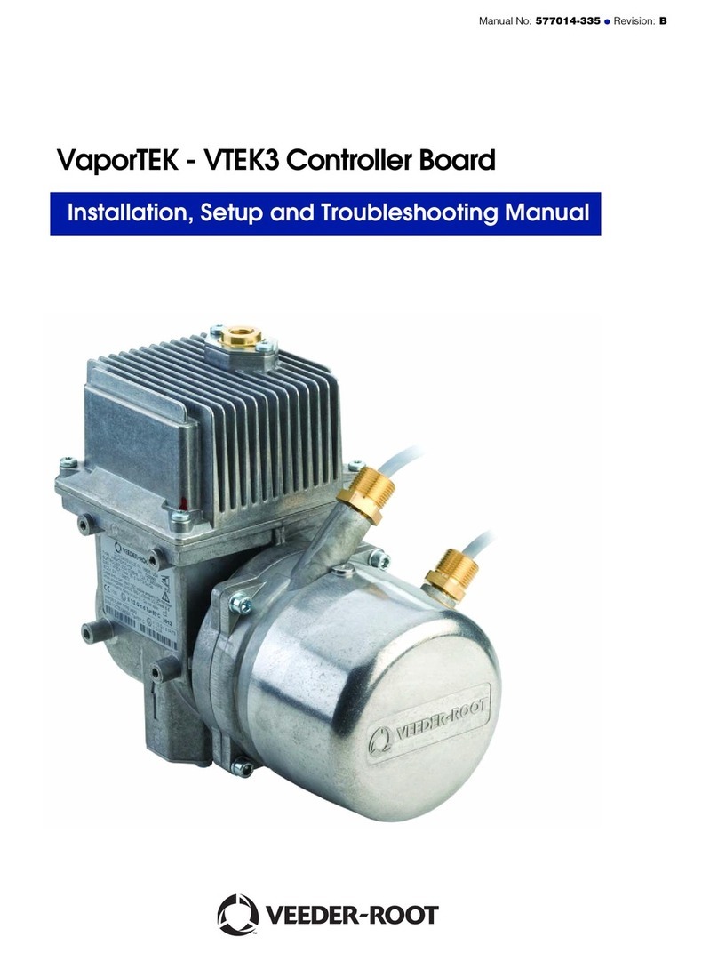
Veeder-Root VaporTEK Setup guide

1 / 4
Veeder - RootCompany
125 Powder Forest Drive
PO B ox 2003
Simsbury, C T 06070
Within the US and C anada: 1.888.561.7942
Outside the US and C anada: +1.860.651.2700
For Technical S upport: 1.800.323.1799
http://www.veeder.com/us/
DEWartungs- und Reparaturanleitung
Manual No. 577014-132, Revision A
Mitteilungen
Veeder-Root übernimmt bezüglich dieser Veröffentlichung keinerlei Garantie, einschließlich, jedoch nicht beschränkt auf, die implizierten Garantien der Marktfähigkeit
und der Eignung für einen bestimmten Zweck.
Veeder-Root ist nicht haftbar für hierin enthaltene Fehler oder für beiläufige Schäden oder Folgeschäden im Zusammenhang mit der
Bereitstellung, der Funktion oder der Nutzung dieser Veröffentlichung.
Veeder-Root behält sich das Recht vor, Systemoptionen oder -funktionen bzw. die Informationen in dieser Veröffentlichung zu ändern.
Diese Veröffentlichung enthält firmeneigene, urheberrechtlich geschützte Informationen. Alle Rechte vorbehalten. Kein Teil dieser Veröffentlichung darf ohne die
vorherige schriftliche Genehmigung von Veeder-Root vervielfältigt, geändert oder in eine andere Sprache übersetzt werden.
Weitere Informationen zur Fehlerbehebung erhalten Sie bei TLS Systems Technical unter der Rufnummer (+1) 800-323-1799 (Rufnummer in den USA).
Für Technische Unterstützung gehen Sie bitte auf unsere Website unten, um den Service-Standort herauszufinden, der Ihnen am
nächsten ist.
http://www.gilbarco.com/eu
Die Firma Veeder–Root oder ihre Vertragsinstallateure können fordern, dass bestimmte Vorrichtungen von den vom Kunden benannten Vertragspart-
nern vor Beginn der Installation eines TLS-Systems installiert werden. Diese Vorrichtungen variieren je nach dem zwischen der Firma Veeder-Root oder
ihren Vertragsinstallateuren und dem Kunden geschlossenen Installationsverträgen. Für Großbritannien bestehen zwei Ebenen der Vorbereitung des
Installationsortes, die nachfolgend beschrieben werden:
INSTALLATIONSEBENE 1
Der Kunde oder der von ihm gewählte Vertragspartner liefert (vorbehaltlich anderer Festlegungen) und installiert folgendes:
• Konsole für Stromversorgung und Erdung.
• Alarm für hohen Füllstand und zugehörige Verkabelung zur TLS-Station. (von Veeder–Root geliefert)
• Stromversorgung und Verkabelung externer Geräte (z.B. Alarm für hohen Füllstand)
• Verkabelung von Peripheriegeräten (z.B. Datenkabel zur Pumpensteuerung und zum Verkaufsterminal)
Einführung Allgemeines 2
• Kanäle für Fühler- und Sensorkabel
• Feldkabel für Fühler
• Fühlersteigleitungen
• Schächte für Grundwassersensoren
• Schächte für Dampfsensoren
• Der Vertragspartner versiegelt alle Kanäle, nachdem der Test des Systems durchgeführt wurde.
INSTALLATIONSEBENE 2
Vom Vertragspartner wird installiert:
• Stromversorgung und Erdung der Konsole.
• Alarm für hohen Füllstand und zugehörige Verkabelung zur TLS-Station. (von Veeder–Root geliefert)
• Stromversorgung und Verkabelung externer Geräte
• Kanäle für Fühler- und Sensorkabel
• Schächte für Grundwassersensoren
• Schächte für Dampfsensoren
• Der Vertragspartner versiegelt alle Kanäle, nachdem der Test des Systems durchgeführt wurde.
Installationsebenen
WARNUNG
Die beiliegenden Anweisungen beachten, um
einen Geräteschaden oder eine Personenver-
letzung zu vermeiden.
Alle zugehörigen Handbücher lesen
Die Kenntnis aller diesbezüglichen Verfahren vor Arbeitsbeginn ist wichtig. Alle
Handbücher komplett durchlesen und verstehen. Wenn Sie ein Verfahren nicht
verstanden haben, fragen Sie jemanden, der es verstanden hat.
SICHERHEITSSYMBOLE
WARNUNG
DIE NICHTBEACHTUNG DER FOLGENDEN WARNUNGEN UND SICHERHEITSMASSNAHMEN KANN
ZU SACH- UND UMWELTSCHÄDEN FÜHREN, DIE SCHWERE VERLETZUNGEN ODER DEN TOD ZUR FOLGE HABEN.
Es ist wesentlich, dass die Warnungen und Anweisungen in diesem Handbuch sorgfältig gelesen und eingehalten werden, um
sowohl den Installateur als auch andere Personen vor schweren und tödlichen Verletzungen zu schützen.

2 / 4
3 Protokollierung
ProtokollSeriennummer SN
Motor VRM2
Pumpe Vapour TE K
Prüfschrittbeschreibung in Ordnungnicht in Ordnung
Kupplung
Pumpe montiert
Drehmoment
Funktions- /Optische Ko ntrolle
Datum:________________________________
Prüfer:________________________________
2.2 Endmontage
Neue Lüfterbaugruppe (630, 620) auf Motorwelle schieben und S chrau-
be (60) mit 12 Nm anziehen. Gewinde mit anaerobem K lebstohern.
Neues Gummielement (600) auf das motorseitige Kupplungselement
stecken. Dabei darauf achten, dass die 3 Mitnehmerzapfen des motor-
seitigen K upplungselementes (630) um eine B ohrung versetzt zu den 3
Mitnehmerzapfen (630) des pumpenseitigen Kupplungselement in das
Gummielement eingreifen .
Pumpe (590) unter B eachtung der K upplungselement- Position auf den
Motorflansch s chieben. P umpenflansch muss an Motor (650) anliegen.
Befestigungsschrauben (90) mit 5-6 Nm anziehen.
Leitungen wieder an Pumpe anschließen.
630 630 620
600 60
90 (4x)
610
Nm
12
Nm
5-6
590
650
WARNUNG
Explosionsgefahr durch Funkenbildung
Pumpe muss mit Gummielement betrieben werden
Korrekten S itz des G ummielementes prüfen.
1 Benötigte Werkzeuge
–
Nm Drehmomentschlüssel
– Innensechskantschlüssel S W 5
2 Montage
2.1 Demontage
Leitungen von der P umpe (590) demontieren
Schraubverbindungen (90) Pumpe-Motor lösen.
Pumpe vom Motor (650) abziehen.
Wenn notwendig Lüfterbaugruppe vom Motor demontieren. Dazu
Schraube (60) lösen und Lüfterbaugruppe von der Motorwelle (610) ab-
ziehen.
630 630 620
600 60
90 (4x)
610
650
590
60 S chraube Lüfterbaugruppe
90 B efestigungsschraube
(Motor-Pumpe Flansch)
590 P umpe
600 G ummielement
610 Motorwelle
620 Lüfterrad
630 K upplungselement
650 Motor
Gasrückführung VaporTEK Pumpe Austauschteil
Die folgenden Informationen sind eine Ergänzung zur Montage- und Gebrauchsanweisung des Gerätes.
Grundsätzlich ist zusätzlich die Montage- und Gebrauchsanweisung des Gerätes zu beachten, in der wichtige
Informationen wie z Sicherheits-hinweise, Aufstellung, elektrischer Anschluss, Reinigung, etc. beschrieben
sind.
Nachrüstungen dürfen nur von einer qualifizier Fachkraft oder unserem
Kundendienst ausgeführt werden.
Reparaturarbeiten, die über die übliche Wartung hinausgehen, sind
nicht erlaubt.
Abbildungen sind
schematisch dargestellt.

3 / 4
Veeder - RootCompany
125 Powder Forest Drive
PO B ox 2003
Simsbury, C T 06070
Within the US and C anada: 1.888.561.7942
Outside the US and C anada: +1.860.651.2700
For Technical S upport: 1.800.323.1799
http://www.veeder.com/us/
ENMaintenance and repair instructions
WARNING
FAILURE TO COMPLY WITH THE FOLLOWING WARNINGS AND SAFETY PRECAUTIONS COULD CAUSE DAMAGE TO
PROPERTY, ENVIRONMENT, RESULTING IN SERIOUS INJURY OR DEATH.
It is essential that the warnings and instructions in this publication are carefully read and followed to protect both
the installer and others from serious or fatal injury.
WARNING
Heed the adjacent intructions to avoid equipment
damage or personal injury.
READ ALL RELATED MANUALS
Knowledge of all related procedures before you begin work is
important. Read and understand all manuals thoroughly. If you do not
understand a procedure, ask someone who does.
Safety Symbols
Contractor Certification Requirements
Notice
Veeder-Root makes no warranty of any kind with regard to this publication, including, but not limited to, the implied warranties of merchant-
ability and fitness for a particular purpose.
Veeder-Root shall not be liable for errors contained herein or for incidental or consequential damages in connection with the furnishing,
performance, or use of this publication.
Veeder-Root reserves the right to change system options or features, or the information contained in this publication.
This publication contains proprietary information which is protected by copyright. All rights reserved. No part of this publication may be
photocopied, reproduced, or translated to another language without the prior written consent of Veeder-Root.
Contact TLS Systems Technical Support for additional troubleshooting information at 800-323-1799.
Veeder-Root requires the following minimum training certifications for contractors who will install and setup the equipment discussed in
this manual:
Installer Certification (Level 1): Contractors holding valid Installer Certification are approved to perform wiring and conduit routing;
equipment mounting; probe, sensor and carbon canister vapor polisher installation; wireless equipment installation; tank and line prepara-
tion; and line leak detector installation.
Technician Certification (Level 2/3): Contractors holding valid Technician Certifications are approved to perform installation checkout,
startup, programming and operations training, system tests, troubleshooting and servicing for all Veeder-Root Series Tank Monitoring
Systems, including Line Leak Detection. In addition, Contractors with the following sub-certification designations are approved to perform
installation checkout, startup, programming, system tests, troubleshooting, service techniques and operations training on the designated
system.
• Wireless 2
• Tall Tank

4 / 4
3 Logging record
Protocol Serial number SN
Motor VRM2
Pump vapour TE K
Test step description OK NOK
Coupling
Pump fitted
Tightening torque
Functional / visual check
Date:________________________________
Tester:________________________________
2.2 Final assembly
Slide the new fan assembly onto the motor shaft (630, 620) and tighten
the screw (60) with 12 Nm tightening torque. S ecure the thread with
anaerobic adhesive.
Place a new rubber element (600) onto the motor end of the coupling el-
ement. When doing so ensure that the 3 drive dogs of the motor end
coupling element (630) are displaced by one borehole to the 3 drive
dogs (630) of the pump end coupling element and engage the rubber el-
ement.
Slide the pump (590) onto the motor flange while taking into considera-
tion the position of the coupling element. The pump flange must lie on
the motor (650).
Tighten the fixing screws (90) with a torque of 5 - 6 Nm.
Re-connect the lines to the pump.
630 630 620
600 60
90 (4x)
610
Nm
12
Nm
5-6
590
650
WARNING
Explosion hazard from spark formation
The pump must be operated with the rubber element
Check for correct seating of the rubber element.
1 Tools required
–
Nm Torque wrench
– Allen key S W 5
2 Installation
2.1 Disassembly
Remove the lines from the pump (590)
Disconnect the pump-motor s crew connections (90).
Pul ump from the motor (650).
If necessary, disassemble the fan assembly from the motor. Disconnect
the screw (60) and pul ssembly from the motor shaft (610).
630 630 620
600 60
90 (4x)
610
650
590
60 Fan assembly screw
90 Fixing s crew (motor pump flange)
590 P ump
600 R ubber element
610 Motor shaft
620 Fan wheel
630 C oupling element
650 Motor
Vapor Recovery VaporTEK Pump Field Replacement
The following information supplements the unit Assembly and Operating In-structions.
Comply with the specifications of the unit Assembly and Operating Instructions as a general
rule. These instructions include important information such as safety instructions and
information on setup, electrical connection, cleaning etc.
Refitting may only be carried out by a qualified person or one of
our service technicians.
Any repairs exceeding routine maintenance
are not permitted.
Images are shown schematically
Other manuals for VaporTEK
2
Table of contents
Languages:
Other Veeder-Root Water Pump manuals
Popular Water Pump manuals by other brands

Beckett
Beckett Fountain Pump M400AUL16 Specifications

SKF
SKF FD3 Assembly instructions

Grundfos
Grundfos APG Series Installation and operating instructions

Speck pumpen
Speck pumpen Zismatic 40/10 WE Operation manual

Grundfos
Grundfos SCALA2 instructions

Grundfos
Grundfos alpha2 l Installation and operating instructions

red lion
red lion 6RLAG-2LST owner's manual

aqua technix
aqua technix AQUA Mini 3 Installation and operation manual

Ragazzini
Ragazzini RC2-Mxl Instructions for use

AIRMAC
AIRMAC DBMX500 manual

Kremlin-Rexson
Kremlin-Rexson FLOWMAX 17 A2 Disassembly/Reassembly

ITT
ITT Goulds Pumps HS Installation, operation and maintenance manual