Vega Industries PEl 6 Quick guide

PEL 6 Marine Sector Light
Installation and Instruction Manual
PEL-6 Sector Light Product Manual
Available colour range Red, White, Green
Subtense 3.5°, 5.0°, 7.5°, 10°, 15°, 20°
This manual applies from serial #:
Calc version: Calc2001
Manual version: 1.1.1
Date released: 21 October 2008
Status: Released by IG
VEGA INDUSTRIES LIMITED

Installation and Operation Manual PEL - 6 © Vega Industries Ltd, April 2008
2
Manual quick reference
WARNING!
DO NOT CONNECT TO ANY POWER SUPPLY BEFORE READING THE
MOUNTING AND INSTALLATION INSTRUCTIONS
PEL 6 POWER SUPPLY REQUIREMENTS
Nominal Input voltage 24 Volts DC
Nominal Current 12 Amps
Product Warranty
Vega warrants that all products supplied are free from labour and material defects, and will repair or replace (at
its option) the whole or any part of the products found to be faulty. The standard warranty is valid for 12
months from the date of dispatch. Vega is not to be liable for any charge beyond the point of delivery,
including installation, alignment or testing. To claim under warranty the product must be returned to the Vega
factory in New Zealand at the users expense.
Patent Notice
The PEL Marine Sector Light has been developed from a prototype developed by the Physics and Engineering
Laboratory of the New Zealand Department of Scientific and Industrial Research. The design concept is fully
protected by world-wide patents held by the New Zealand Government.
VEGA INDUSTRIES LIMITED
21 Heriot Drive, Porirua 5022, New Zealand
Tel: +64-4-237-4393; Fax: +64-4-237-4392
Designers and manufacturers of lighted navigational aids and optical, electronic and electro-mechanical instruments
Description of Change Date manual released Manual version Software version PEL Serial number
Re-issue of manual
-updated formatting April - 08 1.1 Calc2001
Warranty clause added October 2008 1.1.1
AUTHORIZED DISTRIBUTOR
Go Deep International Inc.
10 Watertower Road
Saint John, NB
Canada
E2M7K2
Website:http://www.buoysandlights.com Email:[email protected] Phone: 1-506-633-7850 Fax: 1-506-633-7859
Phone: 1-506-633-7850 Fax: 1-506-633-7859

Installation and Operation Manual PEL - 6 © Vega Industries Ltd, April 2008
3
1.0 General Description.......................................................................................................................... 4
1.1 Introduction......................................................................................................................... 4
1.2 Lamps Used in PEL Sector Lights...................................................................................... 4
1.21 Power Supplies for PEL Sector Lights ............................................................................... 5
1.5 Colour Filter Assembly....................................................................................................... 5
1.6 Intensity Reduction Filter ................................................................................................... 6
1.7 Projection System ............................................................................................................... 7
1.8 Aperture Stop...................................................................................................................... 7
1.9 Air Cooling System ............................................................................................................ 7
1.10 Electric Motors ................................................................................................................... 7
1.11 Electronic Controller........................................................................................................... 7
2.0 Mounting and Installation................................................................................................................. 8
2.1 Acceptance Inspection........................................................................................................ 8
2.2 Exclusion of Moisture......................................................................................................... 8
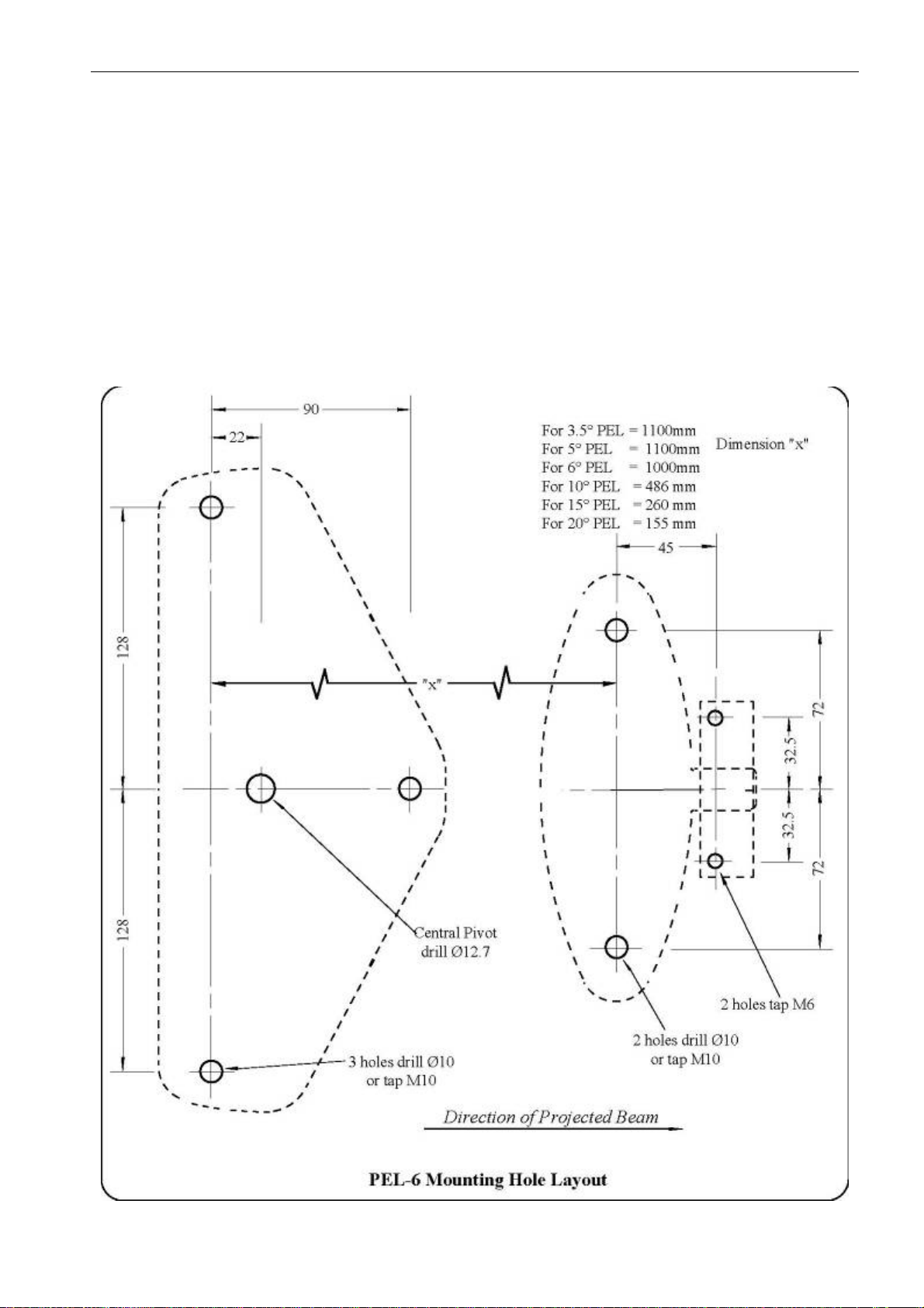
2.3 Physical Mounting.............................................................................................................. 8
2.4 Alignment of Sector Light.................................................................................................. 9
2.5 Masking Stray Light ......................................................................................................... 10
3.1 Input Power Connections.................................................................................................. 10
3.2 CALC (Electronic Controller) Connections ..................................................................... 11
3.3 Stepping Motor Inverters.................................................................................................. 11
4.0 Lampchanger Operation ................................................................................................................. 12
4.1 Fitting of Lamps................................................................................................................ 12
4.2 Lamp Alignment on Lampchanger................................................................................... 13
4.3 Lamp Changer Alignment ................................................................................................ 13
5.3 Parts Listing: Intensity Reduction Filter Assembly.......................................................... 17
6.0 Air Cooling System ........................................................................................................................ 17
7.0 Oscillating Boundary Device (optional extra)................................................................................ 18
7.1 General Description.......................................................................................................... 18
7.2 Mechanical Arrangement.................................................................................................. 18
7.3 Servicing the Oscillating Boundary Device...................................................................... 18
7.5 Reassembly of the Oscillating Boundary Device and Colour Filters............................... 19
7.6 Exploded View ................................................................................................................. 21
7.7 Parts Listing: Intensity Reduction Filter and Oscillating Boundary Device .................... 22
8.0 Maintenance Procedures................................................................................................................. 23
8.1 Objective Lens.................................................................................................................. 23
8.2 Oscillating Boundary........................................................................................................ 23
8.3 Internal Optical Surfaces .................................................................................................. 23
8.4 Aluminised Mirror............................................................................................................ 23
8.5 Filter Glasses..................................................................................................................... 23
8.6 Seals.................................................................................................................................. 24
9.0 Trouble Shooting List..................................................................................................................... 24
9.1 Loss of Intensity or Change in Intensity Profile............................................................... 24
9.2 Poor Sector Resolution ..................................................................................................... 24
9.3 Oscillating Boundary Fails to Oscillate............................................................................ 24
9.4 Lamp Inoperative / Lampchanger Faults.......................................................................... 24
9.5 Electronic Controls ........................................................................................................... 24

Installation and Operation Manual PEL - 6 © Vega Industries Ltd, April 2008
4
1.0 General Description.
1.1 Introduction
The standard light source of the PEL Sector Light is the 250 watt long-life Thorn M36
tungsten-halogen (TH) lamp. A highly efficient and patented optical condenser system
collects most of the available light energy into an intense beam which is emitted through a
precision projection system. The beam is optically separated into accurately controlled
sectors.
These sectors are recognisable by colour alone (normally red, white and green), or by
alternation between two colours of adjacent sectors (when optical coding device is fitted).
Functionally the PEL Sector Light consists of the following integrated sections:
1.2 Lamps Used in PEL Sector Lights
The PEL-6 Sector Light optical system was designed specifically to utilise the special
features of the 2000-hour 250 Watt tungsten halogen lamp designated (M36) which was
originally developed in the UK by Thorn. To our knowledge in 1978 this was the only lamp
available with this label (M36). The original lamps had Ø1.0 mm pins on a 6.35mm pitch, a
Light Centre Length of 33 mm and Max Overall Length of 55mm. In the early 1980’s this pin
diameter was increased to Ø1.25 mm.
In the last few years other lamps from other manufacturers designated ‘M36’ have
appeared on the market. Most of these do not compare with the original ‘M36’ lamp and in
fact are extremely suspect in design. They can degrade the optical performance of the
PEL-6 Sector Light, and also cause damage because they are prone to exploding. Such
explosions can fracture the first (spherical) condenser lens, damage the primary mirror with
shards of flying glass, and coat the optics with a thin film of ash and soot, mainly tungsten
oxide. The first condenser lens can also be cracked by excessive heat - some non-genuine
M36 lamps run at higher temperatures than the original, and the increased resistance of
poorly-adjusted or corroded lampchanger collets can add to the heat load.
Vega now understands that Thorn has sold its plant and lamp designs to GE from whom
Vega now sources lamps. The lamps now sold into Australasia by Thorn, designated ‘M36’
are of Japanese origin, have a shorter LCL and must not be used in PEL-6 Sector Lights.
They have a much shorter life, easily over-heat and are prone to exploding.
If a Tungsten Halogen lamp is operated at a voltage higher than its rated voltage then its
expected life deteriorates rapidly as the operating voltage increases. The envelope
temperature of a TH lamp is in excess of 500° F at rated voltage, so any increases in voltage
will increase the chance of a lamp exploding. If the Spherical Condenser lens is cracked
then boundary resolution is destroyed.
Summary
Use only M36 lamps manufactured by GE. Do not run lamps in excess of 24 Volts when
controlled by CALC-88 controllers. CALC-92, CALC-2000 and CALC-2001 controllers have
pulse-width modulation (PWM) applied to the output to the lamp to ensure that the RMS
voltage does not exceed the nominal value. Size and check the grip tension on the lamp

Installation and Operation Manual PEL - 6 © Vega Industries Ltd, April 2008
5
collets every time lamps are replaced. Ensure the pin size of the lamp is Ø1.25mm
1.21 Power Supplies for PEL Sector Lights
There is a potential problem when using power supplies with a high internal inductance to
drive low-voltage lighted navigation aids. The problem is that when a lamp is switched off
(either at dawn or when it is being periodically flashed), or when a lamp fails at the end of its
life, very large transient voltages can be generated. These voltages - of the order or 100-200
Volts - can cause damage to electronic lamp controllers (eg CALC-2001 and CALC-20)
which operate at typically 12 or 24 Volts.
The reason for the high inductance in the power supply is that an inductive element
(typically a “choke”) is often used in conjunction with a capacitor to form an “LC” circuit
which smoothes the pulsed DC after rectification. Unfortunately, such inductors also store
large amounts of energy during normal operation, and it is the rapid discharge of this
energy which is responsible for the voltage spike when sudden changes are made to the
current flowing.
A further hazard is that when such power supplies are initially installed, typically as a
continuous battery charger into a bank of batteries, the batteries are in good condition and
undamaged. In this situation the batteries may well have sufficient capacity to absorb
voltage spikes and prevent them being passed on to the electronics in the light. However, as
the batteries deteriorate with time, their condition possibly aggravated by poor maintenance
or damage, their capacity to absorb such spikes reduces and more frequent damage to
electronics can result.
1.3 Lamp System
The tungsten-halogen lamp is slightly displaced in the vertical plane from the centre of
curvature of a concave spherical mirror. This mirror gathers the light emitted from the rear of
the lamp and forms a real image of the lamp filament adjacent to the actual filament. The
mirror is a spherical, optically worked concave glass surface onto which aluminium has been
evaporated under vacuum. On anamorphic (wide-angle) lights the displacement may be
horizontal rather than vertical to give a wider light source.
1.4 Aspheric Condenser System
The condenser system is arranged to collect as much light as is practicable from the filament
and its image generated by the mirror, and to form this light into a narrow beam of high
intensity light. In doing so, an enlarged image of the filament (and its mirror image) is
formed between the two projector lenses. This is the source of light which the mariner
actually sees.
1.5 Colour Filter Assembly (and Optional Oscillating Boundary Device)
The colour filter assembly is a set of optically-worked filters located in the illumination plane
of the condenser system and at the focus of the projection lens. The width of the individual
filters is accurately scaled to provide the required sector subtenses.
The “oscillating boundary” device mechanically reciprocates the filter assembly to provide
additional defined sectors. These are characterised by an alternation between the colours of
the solid sectors on either side of the alternating sector.

Installation and Operation Manual PEL - 6 © Vega Industries Ltd, April 2008
6
1.6 Intensity Reduction Filter
This is a neutral density filter which is mechanically inserted into the beam to reduce the
intensity of the emitted light for night operations.

Installation and Operation Manual PEL - 6 © Vega Industries Ltd, April 2008
7
1.7 Projection System
The sharp boundaries of the PEL Sector Light are produced by a two-component positive
projection lens in models with a subtense greater than 10° and a singlet projection lens in
the case of the 5° and 3.5° models. This system forms an enlarged image of the coding
device (coloured filters) at a considerable distance from its focus. Sector positions are
determined solely by the relative positions of coding device and projection lens, and are
independent of lamp filament position, errors in which can affect only the beam intensity of
the lamp.
1.8 Aperture Stop
The boundary definition is further enhanced by an aperture stop situated between the two
projection lens components. The aperture stop reduces the amount of light which is
scattered outside the beam angle, and also enables a long-life filament lamp such as the
M36 to be used without incurring any loss of boundary definition.
1.9 Air Cooling System
Because the PEL Sector Light is a sealed unit, a slow speed internal fan is used to
move the air through a fixed circuit enabling the inside temperature to be held at an
acceptably low level.
1.10 Electric Motors
There are up to three motors in this Sector Light - a DC Brushless type used in the cooling
fan, and stepper motors to drive the neutral density filter and optional oscillating boundary
device. Stepper motors are employed where speed control and good reliability in high
temperature situations are essential.
1.11 Electronic Controller
The total electronic monitoring and control system, including inverter supplies, is
controlled by a micro-processor in a module called the CALC-2001. This is a sealed unit
contained within the Light. Up to two sealed converters can be mounted directly to this
module.

Installation and Operation Manual PEL - 6 © Vega Industries Ltd, April 2008
8
2.0 Mounting and Installation
2.1 Acceptance Inspection
Before connecting the sector light to any power supply, the following steps should be carried
out:
2.1.1 After removing the unit from the packing case, an inspection should be carried out to
check that no damage has occurred during transit.
2.1.2 Review this manual and become familiar with the general layout of components.
2.1.3 Remove Rear Cover. NOTE: If cover is not totally removed, support underside
of rear cover otherwise damage to CALC-2001 may result.
2.1.4 Remove packing around Suspension Springs of oscillating boundary
mechanism (if installed). NOTE: Packing will be on both sides.
2.1.5 Remove packing around brilliancy control mechanism.
2.2 Exclusion of Moisture - THIS IS VERY IMPORTANT
2.2.1 PEL Sector Lights run at high internal temperatures. One of the common problems
associated with this type of system is condensation, which is introduced when the
light is opened for service or replacement of lamps.
2.2.2 Where it is impracticable to house the light, properly pre-dried packs of silica gel
should be placed in convenient places around the lampchanger area of the light. PEL
Sector Lights are tested to hold 6 psi internal pressure, and it is extremely rare for the
ingress of moisture to be associated with the failure of a seal. When servicing, ensure
that the can-fastening knobs are properly tightened to evenly compress the O-Ring
seal.
2.3 Physical Mounting
2.3.1 The sector light can now be mounted and aligned. The PEL light has two mounting
bases. Care must be taken to ensure that the mating surface is flat and no distortion
is introduced to the light itself when mounting.
2.3.2 In order to achieve the high degree of accuracy of which the PEL Sector Light is
capable, it is essential that the mounting location is not capable of being torsionally
deflected more than 0.2 mm per metre in azimuth under wind loading and other
forces likely to be encountered.
2.3.3 Mounting holes should be drilled to the dimensions shown below. Note that the two
bases are spaced differently for different sizes of sector light.
2.3.4 The “rear” base incorporates a recess for a 12.6 mm Ø (0.5 inch Ø) pin, on which the
light can be pivoted during the alignment phase. To permit extremely fine adjustment
of azimuth angle the “front” mount incorporates a pair of trimming screws.

Installation and Operation Manual PEL - 6 © Vega Industries Ltd, April 2008
9
2.4 Alignment of Sector Light
2.4.1 Adjust the angle of elevation of the beam so that the vertical centre is at the average
height of a ship’s bridge at the maximum range at which the light is used. Align the
sector pattern in azimuth using an observer located on the boundary between two
adjacent sectors.
2.4.2 Sector positions should be checked by survey, and the location of the sector
boundaries should be verified from the waterway before commissioning.

Installation and Operation Manual PEL - 6 © Vega Industries Ltd, April 2008
10
2.5 Masking Stray Light
2.5.1 In an optical projection system at least 0.5% of the light will be scattered by the last
lens surface, and even more if the lens is not completely clean. In the case of a very
powerful sector light there can be enough stray light for an observer outside the
beam to think he or she is inside the beam. This problem may arise with PEL-6
Sector Lights of 5° subtense or less, and is possible with 10° lights at full brilliance at
night against a black background.
2.5.2 PEL-3 Series Lights of small subtense angle are masked with a barrel extension. With
the larger aperture of a PEL-6 (Mark VI) PEL Sector Light this is impractical. The
problem can be largely alleviated by placing a pair of vertical plates some distance in
front of the lens (like blinkers on a horse) to mask the lens from an observer outside
the beam.3.0 Electrical Supply and Circuitry
3.1 Input Power Connections (WARNING)
3.1.1 The PEL Sector Light is supplied fully wired and ready for use. This Sector Light
must be connected to a 24V DC supply which is sufficiently smoothed (eg has a
large enough capacitor across the output of the supply which is the input to the
light) to ensure no high voltage spikes can damage the microprocessor-based
control system.
3.1.2 Prior to switching on any power, please ensure that the power supply is 24 Volts DC
and that Brown = Positive, and Blue = Negative. The absolute maximum voltage must
not exceed 28 V DC. It is normal to energize from a battery bank with “battery-
charger float.”
INPUT CONNECTIONS: BROWN = positive 24V DC
BLUE = negative 24V DC
3.1.3 The voltage at the lamp terminals should normally be at the nominal voltage of the
lamps installed when a lamp of the correct wattage is installed and switched on.
Excessive voltage will reduce lamp life but low voltage will reduce light output while
extending lamp life. Low voltage is therefore acceptable, or even desirable in some
cases. Special limitations apply to tungsten-halogen lamps.
3.1.4 Vega PF and TH lampchangers can be operated on either AC or DC, 12 or 24 volts
depending on the lamp requirements. The DC polarity is of no consequence and the
frame of the lampchanger is insulated from the electrical system.

Installation and Operation Manual PEL - 6 © Vega Industries Ltd, April 2008
11
3.2 CALC (Electronic Controller) Connections
3.2.1 The CALC-2001 unit electronically controls all the functions performed by the Sector
Light. This includes intensity changes for day/night operation, the imposition of flash
characters if required, and drives for stepping motors.
3.3 Stepping Motor Inverters
3.3.1 The mechanically-inserted Intensity Reduction filter is driven into position by a
stepping motor, which is powered from an inverter attached to the CALC-2001. This
stepping motor acts through a Vega 56.25:1 reduction gearbox with built-in constant-
velocity coupling to smooth out the steps from the motor. Two micro-switches, ‘A’
and ‘B’, are used to define the ‘park’ position of the Intensity Reduction filter.
3.3.2 The optional Oscillating Boundary device (where fitted) is driven by a similar
stepping motor acting through a 7.5:1 Vega reduction gearbox with built-in
constant-velocity coupling.

Installation and Operation Manual PEL - 6 © Vega Industries Ltd, April 2008
12
4.0 Lampchanger Operation
A special Vega Lampchanger is required for the PEL Sector Light to carry the high currents
drawn by the lamps, to provide the special collet-mounting system, and to fit within the tight
confines of the optical condenser system.
4.1 Fitting of Lamps
4.1.1 The following instructions apply to M-series 50, 100 and 250 watt lamps as fitted
to the PEL-6 Sector Light. These lamps have a bi-pin base and must be fitted
carefully into a twin-collet lamp-holder.
4.1.2 The mounting system does not provide automatic focusing - refer to section 4.2 for
positioning the lamp correctly on the lampchanger, and section 4.2 for lampchanger
alignment. Both these procedures must be followed correctly to ensure that each
lamp is in its proper focus.
4.1.3 The VLC-153A lampchanger is fitted with spring-loaded collets to ensure reliable
gripping of the lamp pins. No special adjustment of the collets is required prior to
fitting lamps.
4.1.4 A special collet-opening tool is attached to the lampchanger with a small knurled
bolt, Undo the bolt and remove the tool. Use as shown below to open both collets at
once, then slip the lap in place.
Slip tool over both
collets at the same time Press down on tool to
open collet jaws Fit lamp while jaws are
open Remove collet tool,
lamp is locked into

Installation and Operation Manual PEL - 6 © Vega Industries Ltd, April 2008
13
4.2 Lamp Alignment on Lampchanger
4.2.1 Each TH lamp must be correctly aligned in the lampchanger during fitting. Note
that TH lamps are not to be handled with the fingers. This shortens the lamp life
considerably, as oils on the fingers react with the quartz material of the lamp
envelope. It is acceptable to use the the lamp wrapping material as an insulator
when fitting and adjusting TH lamps.
4.2.2 The filament position must be correctly adjusted for each lamp fitted. Lamp
adjustment must be performed prior to any adjustment of the lampchanger. Use
gentle pressure to move each lamp into its correct position.
4.2.3 When fitting the lamps, all collets must grip the lamp pins firmly. If there is not
a very firm contact between collets and lamp pins the collets will heat up, and in
extreme cases burn away.
4.2.4 To adjust the lamp filament position, place the slotted tube over the lamp as shown.
Line up and sight through the pairs of wide and narrow slots in turn. When the lamp is
correctly installed, the filament will exactly fill the slots in both directions. Refer to
Figures 2A and 2B below. This alignment is repeated for each lamp on the
lampchanger.
Filament Position Alignment
4.3 Lamp Changer Alignment
4.3.1 The following instructions apply to Vega TH 50/100 watt (VLC-151) and TH 250
watt (VLC-152 and VLC-152A) Lampchangers as fitted to the PEL-6 Sector Light.
4.3.2 Correct lamp positioning is important to obtain maximum intensity from the PEL
Sector Light. The concave mirror which is located directly behind the lamp is required
to produce an inverted, real image of the lamp filament directly above the actual lamp
filament. The lampchanger must be adjusted to bring each lamp into a position where
this occurs.
4.3.3 The upper (reflected) image must be directly above and adjacent to the lower (real)
image, nearly touching it and in the same plane. The view from above is sometimes

Installation and Operation Manual PEL - 6 © Vega Industries Ltd, April 2008
14
distorted by irregular lamp envelope contours, but views from each side permit
accurate positioning.
4.3.4 The lampchanger base is held down by two 4mm laterally located fixing screws, C
and D. Two 3mm screws (A and B - see diagram) on the longitudinal axis provide for
vertical height adjustment and also permit minor fore-and-aft adjustment of the
filament position. If the lampchanger has been disturbed for any reason, re-
adjustment of the filament position in relation to the optical axis of the condenser will
be necessary.
4.3.5 Fit a lamp into one of the six sockets. Follow the procedure above to accurately
position the filament of this lamp in relation to the turret and hence the other lamps as
they are installed.
4.3.6 Set the first lamp at the top of the changer and apply reduced voltage to the changer
supply terminals - about 1/3 of the nominal supply voltage.
4.3.7 Examine the filament image reflections in the condenser lens (through welding
goggles), from the three views depicted in the filament image positioning diagram
in Section 4.1 above.

Installation and Operation Manual PEL - 6 © Vega Industries Ltd, April 2008
15
4.3.8 Have the hold-down screws entered into the lampchanger shelf threads but free
to permit the base to be raised to the correct height and tilted laterally and fore-
and-aft. Hold the base down by hand if necessary during the following
operations.
4.3.9 Adjust the height (screws A,B) keeping the base approximately level until the
direct image is below the reflected image - just meeting it with no gap and no
overlap. It will be found that adjustment of the screws affects the fore-and-aft
relationship of the two images, as well as the height. When the images lie in the
same plane as shown, this adjustment is correct.
4.3.10 Use a long slim screwdriver to lightly tighten the hold down screws, adjusting them to
bring the height screws into firm contact with the lampchanger shelf. It will be found
that relative adjustment of these screws affects the lateral relationship of the two
images which should now be made to conform to the positioning diagram.
4.3.11 Now re-check all aspects of the image relationship - height, fore-and-aft and laterally.
Tightening any of the four screws will now fix the changer firmly. Careful selection of
the screw or screws tightened will serve to correct any minor errors in the image
pattern.
4.3.14 Make sure that the lampchanger is positively held down and not liable to shift in
service. Do not tighten the screws to the extent that they distort the base of the
lampchanger.
A

Installation and Operation Manual PEL - 6 © Vega Industries Ltd, April 2008
16
5.0 Intensity Reduction Mechanism
5.1 General Description
The out-put intensity of the PEL-6 Sector Light is controlled automatically for day and night
requirements. A Light Dependent Resistor (LDR) senses the light level in order to drive a
relay which in turn sets the direction of a stepper motor. The motor in turn drives a nickel-
coated duran filter into the beam between the condenser and filter systems. The travel of
the motor is limit controlled through two micro-switches, which park the Neutral Density
(ND) Filter in either the day or night positions. For a 5° light, the filter transmission is
normally set at 5%; for a 10° light it is set at 25%. For other sizes the transmission is
proportion to these values to take into account the maximum intensity required at night.
The ND filter can be manufactured to suit a customer’s requirements for any percentage
value of transmittance.
5.2 Exploded View

Installation and Operation Manual PEL - 6 © Vega Industries Ltd, April 2008
17
5.3 Parts Listing: Intensity Reduction Filter Assembly
5.3.1 Parts Illustrated in Diagram
Key Number Part Number Description
1 6-289-001 Focusing Ring
2 6-289-002 Filter Plate Assembly
3 6-289-003 Pivot Sector Plate
4 6-289-004 Intensity Filter Frame
5 6-289-005 Intensity Filter
6 6-289-006 Intensity Filter Spring
7 6-289-007 Intensity Filter Retaining Plate
8 6-289-008 Intensity Filter Pivot
9 6-289-009 Cable Retaining Clips
10 6-289-010 Fan Housing
11 6-289-011 Cable Retainer
12 6-289-012 Heat Shield
13 6-289-013 Torsional Damping Gearbox 56:1 reduction
14 6-289-014 Filter Drive Motor
15 6-289-015 Motor Cable Retainer
16 6-289-016 Microswitch ‘A’ and ‘B’
17 6-289-017 Drive Cam
18 6-289-018 Drive Shaft
19 6-289-019 Crank Arm
20 6-289-020 Shear Pin
21 6-289-021 Con Rod
5.3.1 Parts Not Illustrated in Diagram
6-289-022 Condenser Housing
6-289-023 Lampchanger
6-289-024 Fan
6-289-025 Fan Connecting Cable
6-289-026 Intensity Filter Connecting Cable
6-289-027 CALC-2000
6-289-028 L.D.R. Retaining Clip
6-289-029 Focusing Locking Screw
6.0 Air Cooling System
The PEL Sector Light utilizes its total surface area to dissipate the heat generated by the
250 watt lamp. A standard 3" computer fan is used to circulate air internally through a fixed
circuit, ensuring maximum heat dissipation. It would be advisable to replace this fan at least
every TWO years to ensure maximum reliability.

Installation and Operation Manual PEL - 6 © Vega Industries Ltd, April 2008
18
7.0 Oscillating Boundary Device (optional extra)
7.1 General Description
A filter plate holding the glass filters (typically Red, White and Green) oscillates laterally to
produce up to seven separate sectors, three of which are steady colours. In the other four
sectors the colour either alternates between the colours in the adjacent sectors, or flashes.
As a viewer moves away from the optical axis of the light from within the colour/white
boundary sector, the duration of the colour flash increases and the duration of the white
decreases. In the flashing sectors, the eclipse time increases as the viewer moves away
from the axis.
7.2 Mechanical Arrangement
The filter assembly is suspended on phosphor bronze flexible straps and is oscillated
laterally in a sinusoidal manner using a rotating crank and connecting rod. A gear box
reduces the motor speed to give a period of oscillation of three seconds. The gearbox
incorporates a flywheel and flexible motor coupling to eliminate torsional vibration and
extend gear life.
7.3 Servicing the Oscillating Boundary Device
The central position and travel limits of the filter assembly are indicated by a pointer
registering with scribed marks. If the mechanism is disturbed for servicing, the filters must
be centralised on these marks at re-assembly to avoid a sector position change. The
connecting rod is adjustable by half turns.
All moving parts should be lubricated every 12 months. The gearboxes are lubricated with
BP ZSOO Semi-Fliud Grease, or ENERGREASE FG OO.EP. To replenish the lubricant in
the gearbox remove the gearbox from the light, unscrew the end plate and lifted it off. The
groove around the side of the large gear should be judiciously filled with grease then the
gearbox reassembled. The four small bearing races in the gearbox are shielded but not
sealed, and are lubricated by the grease in the gearbox. The rubber damper at the drive dog
should be examined for wear (and preferably replaced). In any case apply two drops of
glycerine to the rubber to lubricate it.
The motors are fitted with self-aligning sintered-bronze bearings, and one drop of light
mineral oil (sewing machine grade) should be applied to the bearing at each end of the
motor. At the same time apply two drops of light mineral oil to each motor shaft bearing.
7.4 Dismantling the Oscillating Boundary Device and Colour Filters
The following procedure should be adopted if at any time the moving assembly has to be
removed from the condenser/filter system, keeping glassware clean.
7.4.1 Locate the complete light on a clean, well lit workshop bench and completely
remove the rear cover. Remove all lamps.
7.4.2 Loosen the big-end fixing screw, and gently slide the split boss off the ball-race.
Avoid bending or straining the light coupling rod at all times.
7.4.3 Loosen the four grub screws on the drive sleeve and intensity cam.

Installation and Operation Manual PEL - 6 © Vega Industries Ltd, April 2008
19
7.4.4 Unscrew the four 4mm screws holding the condenser assembly and withdraw it off
the two locating pins, leaving the 6-plate filter assembly on the pins.
7.4.5 Carefully remove the filter plates, intensity frame and drive-rod as one unit off the
locating pins. Remove intensity frame and rods. Withdraw brilliancy control assembly.
7.4.6 Use two of the 4mm screws to hold the plates together and withdraw the filter
assembly complete, taking care not to damage the push rod.
7.4.7 Lie the filter assembly on its back (large plate) and remove the top fixed plate.
Release the lower spring strap screws. Note the relieved inner surface of the pads
under the screw heads, for reassembly. Separate the 4-plate moving assembly from
the springs.
7.4.8 Remove one or both of the lower attachment fittings only if required to release the
upper plate of the 4-plate coloured filter assembly.
7.4.9 Release the 6 x 3mm countersunk screws holding the side plates and lift off the top
plate only. Use two only 3 mm screws to locate the lower plates while the filter
glasses are being removed or refitted.
7.4.10 Release the filter plate retention spring, being careful not to chip the edges of the filter
glasses in the process.
7.4.11 Remove the three or more filter glasses.
7.5 Reassembly of the Oscillating Boundary Device and Colour Filters
Reassembly is generally the reverse of the disassembly process, but the
following points should be noted:
7.5.1 Clean the filter plates carefully with methylated spirits and wipe off with cotton
wool or facial tissue. Do not subsequently finger the glass.
7.5.2 Make sure that the polished mating glass edges of the colour filters are entirely
clean and free from fluff or grit, as intimate contact is essential.
7.5.3 The mating edges are sharp and fragile and care must be taken not to chip them
or apply pressure to them until the glass is lying flat in its holder.
7.5.4 Inspect the filters to ensure they are absolutely clean. Blow off any dust on the
surface because these specks appear greatly magnified in the projected beam.
If stronger measures are necessary gently swab the surface with a wad of clean
cotton wool damped with isopropyl alcohol or high-grade methylated spirits,
making sure not to trap any particles in the filter edges. Great care must be
taken doing this.
7.5.5 When reassembly is completed, ensure that the oscillating components swing

Installation and Operation Manual PEL - 6 © Vega Industries Ltd, April 2008
20
freely and generally parallel to the fixed plates. Loosen the suspension strap
screws to aid this, and retighten while the plate is held in its proper relationship.
7.5.6 Make sure that the connecting rod lies parallel to the oscillating plane. When
clamping the big end onto the ballrace ensure that correct alignment is achieved.
7.5.7 Before wiring to the inverter board check that the unit does not interfere with the front
or rear plate when oscillating. Turn the crank arm to check the clearances.
Adjustment can be made by loosening the suspension-strap screws, holding the
suspension strap to the correct position, and retightening.
Table of contents