VEGASON 51K …53K 5
Product description
1.2 Application features
Applications
•Level measurement of all liquids
•Level measurement of solids
(only short measuring distances) such as
e.g.:
coal, ore, stones, stone dust, cement,
gravel, crushed stones, sand, sugar, salt,
cereals, flour, granules, powder, dusts,
saw dust, wood chips
•Flow measurement on different flumes
•Gauge measurement, distance measure-
ment, object monitoring and conveyor belt
monitoring
Two-wire technology
•Supply and output signal on one two-wire
line (Loop powered)
•4 …20 mA-output signal
Rugged and precise
•Unaffected by product features such as
density, conductivity, dielectric constant …
•Suitable for aggressive substances
•Measuring ranges 0,25 m …15 m
Adjustment choice
•With adjustment software VEGA Visual
Operating (VVO) on PC
•With detachable adjustment module
MINICOM
•With the HART®-Handheld
•Measured value indication integrated in the
sensor
•Optional indication separate from the sen-
sor
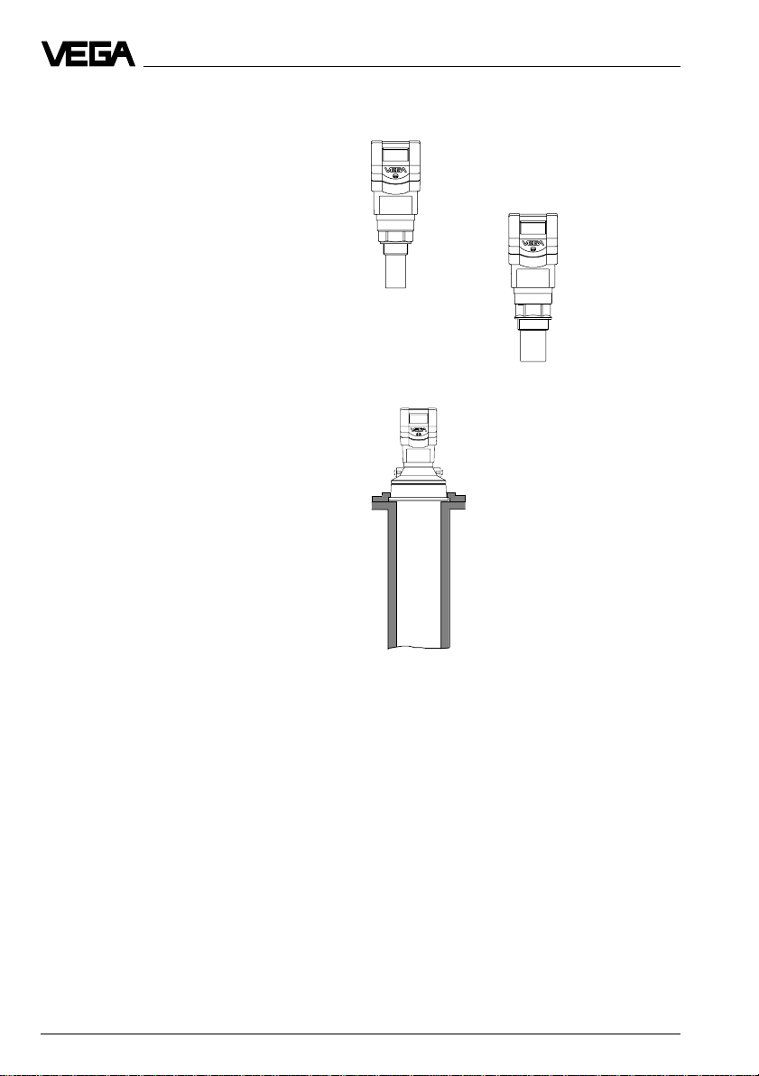
Connection for each process
•G 11/2 A, 11/2" NPT
•G 2 A, 2" NPT
•Compression flange DN 100, ANSI 4"
Approvals
•CENELEC, ATEX, PTB, FM, CSA, ABS,
LRS, GL, LR, FCC
1.3 Adjustment
Each measuring distance is different, there-
fore each ultrasonic sensor must be given
some basic information on the application
and the environment, e.g. you need to inform
the sensor which level means “empty“and
which level “full“. Apart from this “empty and
full adjustment“, a number of other adjust-
ments can also be carried out with
VEGASON ultrasonic sensors.
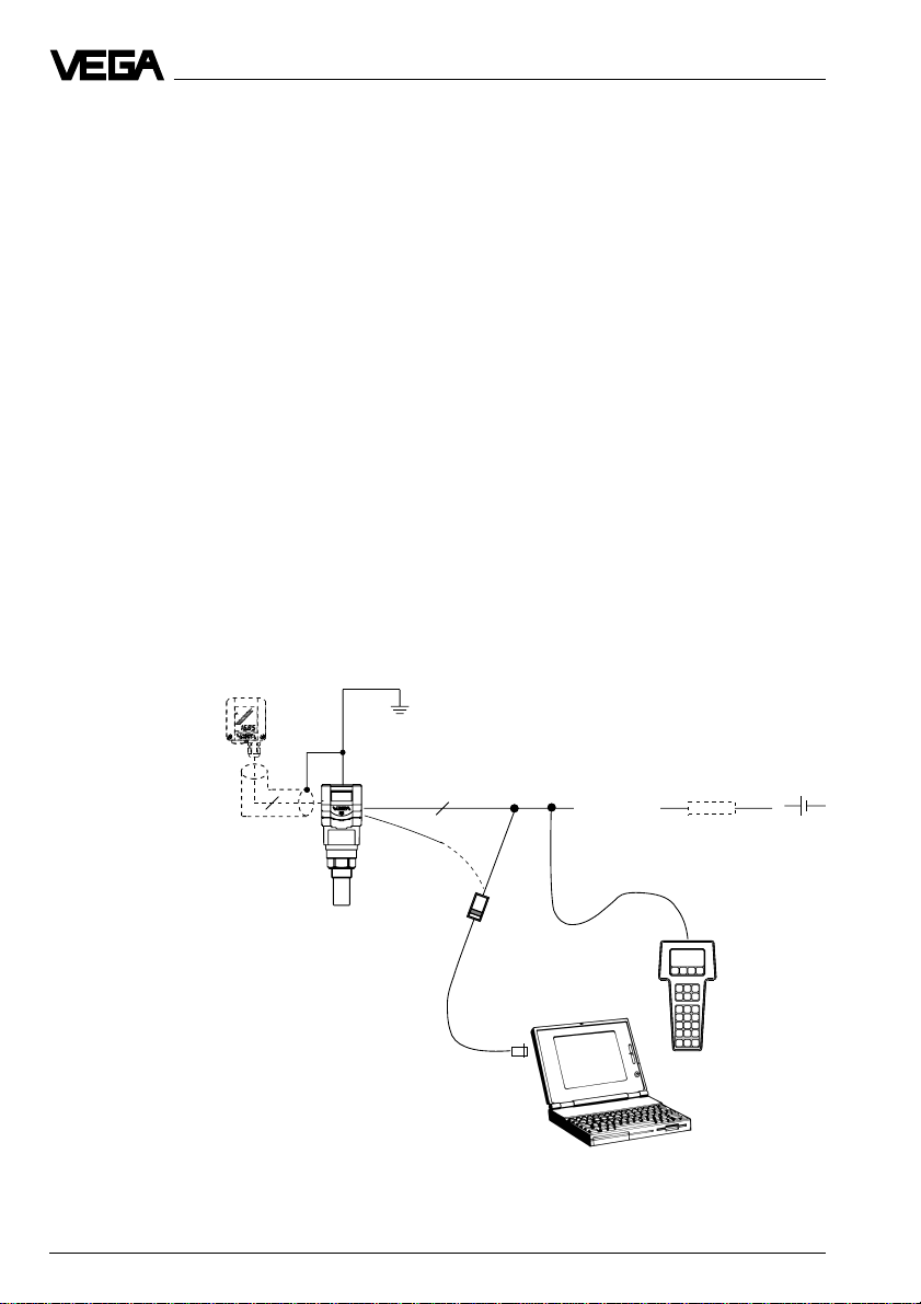
The adjustment and parameter adjustment of
the ultrasonic sensors are carried out with
- the PC
- the detachable adjustment module MINI-
COM
- the HART®--Handheld
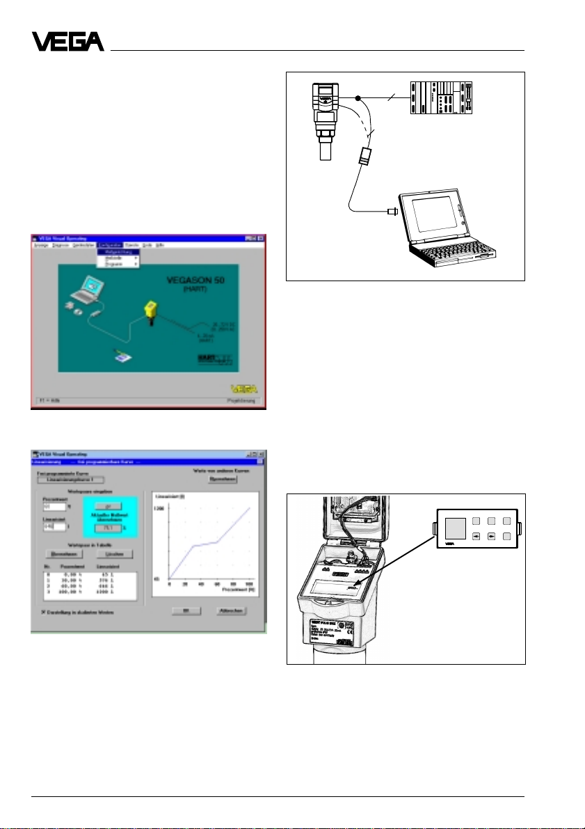
Adjustment with PC
The set-up and adjustment of the ultrasonic
sensors is generally made on the PC with the
adjustment program VEGA Visual Operating
(VVO) under Windows®.
The program leads quickly through the ad-
justment and parameter adjustment via pic-
tures, graphics and process visualisations.
Adjustment with the PC on the analogue 4 …20 mA-
signal and supply line or directly on the sensor (four-
wire sensor)
2
2
4 ...20 mA