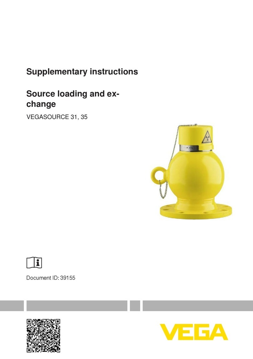
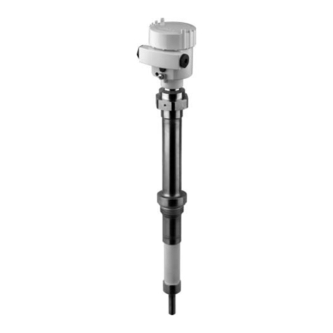
Vega MINITRAC 31 User manual

Operating Instructions
Radiometric sensor for density
measurement
MINITRAC 31
Foundation Fieldbus
Document ID: 41782

2
Contents
MINITRAC 31 • Foundation Fieldbus
41782-EN-211203
Contents
1 About this document ............................................................................................................... 4
1.1 Function ........................................................................................................................... 4
1.2 Target group ..................................................................................................................... 4
1.3 Symbols used................................................................................................................... 4
2 For your safety ......................................................................................................................... 5
2.1 Authorised personnel ....................................................................................................... 5
2.2 Appropriate use................................................................................................................ 5
2.3 Warning about incorrect use............................................................................................. 5
2.4 General safety instructions............................................................................................... 5
2.5 EU conformity................................................................................................................... 6
2.6 NAMUR recommendations .............................................................................................. 6
2.7 Installation and operation in the USA and Canada ........................................................... 6
2.8 Environmental instructions ............................................................................................... 6
3 Product description ................................................................................................................. 7
3.1 Conguration.................................................................................................................... 7
3.2 Principle of operation........................................................................................................ 8
3.3 Packaging, transport and storage................................................................................... 10
3.4 Accessories.................................................................................................................... 10
3.5 Corresponding source container .................................................................................... 12
4 Mounting................................................................................................................................. 14
4.1 General instructions ....................................................................................................... 14
4.2 Mounting instructions ..................................................................................................... 15
5 Connecting to power supply................................................................................................. 21
5.1 Preparing the connection ............................................................................................... 21
5.2 Connection-Density,massowratemeasurement....................................................... 24
5.3 Connection - Level detection.......................................................................................... 27
6 Set up with the display and adjustment module ................................................................ 30
6.1 Insert display and adjustment module............................................................................ 30
6.2 Adjustment system......................................................................................................... 31
6.3 Parameter adjustment - Level measurement .................................................................. 32
6.4 Parameter adjustment - Density measurement .............................................................. 36
6.5 Parameter adjustment - Point level detection.................................................................. 48
6.6 Parameter adjustment - X-ray alarm ............................................................................... 58
6.7 Parameter adjustment - Real value correction................................................................ 60
6.8 Saving the parameterisation data................................................................................... 62
7 Setup with PACTware............................................................................................................. 63
7.1 Connect the PC.............................................................................................................. 63
7.2 ParameteradjustmentwithPACTware............................................................................ 63
7.3 Saving the parameterisation data................................................................................... 64
8 Set up with other systems .................................................................................................... 65
8.1 DD adjustment programs ............................................................................................... 65
8.2 Field Communicator 375, 475 ........................................................................................ 65
9 Diagnostics and servicing .................................................................................................... 66
9.1 Maintenance .................................................................................................................. 66
9.2 Status messages............................................................................................................ 66

3
Contents
MINITRAC 31 • Foundation Fieldbus
41782-EN-211203
9.3 Rectify faults................................................................................................................... 69
9.4 Exchanging the electronics module................................................................................ 70
9.5 Softwareupdate ............................................................................................................. 71
9.6 Howtoproceedifarepairisnecessary.......................................................................... 71
10 Dismount................................................................................................................................. 73
10.1 Dismounting steps.......................................................................................................... 73
10.2 Disposal ......................................................................................................................... 73
11 Supplement ............................................................................................................................ 74
11.1 Technical data ................................................................................................................ 74
11.2 Device communication Foundation Fieldbus.................................................................. 79
11.3 Dimensions .................................................................................................................... 83
11.4 Industrial property rights................................................................................................. 86
11.5 Trademark ...................................................................................................................... 86
Safety instructions for Ex areas
TakenoteoftheExspecicsafetyinstructionsforExapplications.
These instructions are attached as documents to each instrument
withExapprovalandarepartoftheoperatinginstructions.
Editing status: 2021-11-25

4
1 About this document
MINITRAC 31 • Foundation Fieldbus
41782-EN-211203
1 About this document
1.1 Function
This instruction provides all the information you need for mounting,
connectionandsetupaswellasimportantinstructionsformainte-
nance,faultrectication,theexchangeofpartsandthesafetyofthe
user. Please read this information before putting the instrument into
operation and keep this manual accessible in the immediate vicinity
of the device.
1.2 Target group
This operating instructions manual is directed to trained personnel.
Thecontentsofthismanualmustbemadeavailabletothequalied
personnel and implemented.
1.3 Symbols used
Document ID
This symbol on the front page of this instruction refers to the Docu-
ment ID. By entering the Document ID on www.vega.comyouwill
reachthedocumentdownload.
Information, note, tip: This symbol indicates helpful additional infor-
mationandtipsforsuccessfulwork.
Note: This symbol indicates notes to prevent failures, malfunctions,
damage to devices or plants.
Caution:Non-observanceoftheinformationmarkedwiththissymbol
may result in personal injury.
Warning:Non-observanceoftheinformationmarkedwiththissymbol
may result in serious or fatal personal injury.
Danger: Non-observanceoftheinformationmarkedwiththissymbol
results in serious or fatal personal injury.
Ex applications
This symbol indicates special instructions for Ex applications.
• List
Thedotsetinfrontindicatesalistwithnoimpliedsequence.
1 Sequence of actions
Numbers set in front indicate successive steps in a procedure.
Battery disposal
This symbol indicates special information about the disposal of bat-
teries and accumulators.

5
2 For your safety
MINITRAC 31 • Foundation Fieldbus
41782-EN-211203
2 For your safety
2.1 Authorised personnel
All operations described in this documentation must be carried out
onlybytrained,qualiedpersonnelauthorisedbytheplantoperator.
Duringworkonandwiththedevice,therequiredpersonalprotective
equipmentmustalwaysbeworn.
2.2 Appropriate use
The MINITRAC 31 is a sensor for density measurement and level
detection.
Youcannddetailedinformationabouttheareaofapplicationin
chapter " Product description".
Operational reliability is ensured only if the instrument is properly
usedaccordingtothespecicationsintheoperatinginstructions
manualaswellaspossiblesupplementaryinstructions.
2.3 Warning about incorrect use
Inappropriate or incorrect use of this product can give rise to applica-
tion-specichazards,e.g.vesseloverllthroughincorrectmounting
or adjustment. Damage to property and persons or environmental
contamination can result. Also, the protective characteristics of the
instrument can be impaired.
2.4 General safety instructions
Thisisastate-of-the-artinstrumentcomplyingwithallprevailing
regulations and directives. The instrument must only be operated in a
technicallyawlessandreliablecondition.Theoperatorisresponsi-
ble for the trouble-free operation of the instrument. When measuring
aggressive or corrosive media that can cause a dangerous situation
if the instrument malfunctions, the operator has to implement suitable
measures to make sure the instrument is functioning properly.
The safety instructions in this operating instructions manual, the na-
tionalinstallationstandardsaswellasthevalidsafetyregulationsand
accident prevention rules must be observed by the user.
Forsafetyandwarrantyreasons,anyinvasiveworkonthedevice
beyond that described in the operating instructions manual may be
carried out only by personnel authorised by the manufacturer. Arbi-
traryconversionsormodicationsareexplicitlyforbidden.Forsafety
reasons,onlytheaccessoryspeciedbythemanufacturermustbe
used.
To avoid any danger, the safety approval markings and safety tips on
the device must also be observed.
This measuring system uses gamma rays. Therefore take note of the
instructions for radiation protection in chapter " Product description".
Anyworkonthesourcecontainermayonlybecarriedoutunderthe
supervisionofaqualiedradiationprotectionocer.

6
2 For your safety
MINITRAC 31 • Foundation Fieldbus
41782-EN-211203
2.5 EU conformity
ThedevicefullsthelegalrequirementsoftheapplicableEUdirec-
tives.ByaxingtheCEmarking,weconrmtheconformityofthe
instrumentwiththesedirectives.
The EU conformity declaration can be found on our homepage.
Electromagnetic compatibility
Instrumentswithplastichousingaredesignedforuseinanindustrial
environment. Nevertheless, electromagnetic interference from electri-
cal conductors and radiated emissions must be taken into account,
asisusualwithclassAinstrumentsaccordingtoEN61326-1.Ifthe
instrumentisusedinadierentenvironment,theelectromagnetic
compatibility to other instruments must be ensured by suitable meas-
ures.
2.6 NAMUR recommendations
NAMUR is the automation technology user association in the process
industry in Germany. The published NAMUR recommendations are
acceptedasthestandardineldinstrumentation.
ThedevicefullstherequirementsofthefollowingNAMURrecom-
mendations:
• NE 21 – Electromagnetic compatibility of equipment
• NE 43 – Signal level for fault information from measuring transduc-
ers
• NE53–Compatibilityofelddevicesanddisplay/adjustment
components
• NE107–Self-monitoringanddiagnosisofelddevices
For further information see www.namur.de.
2.7 Installation and operation in the USA and
Canada
ThisinformationisonlyvalidforUSAandCanada.Hencethefollow-
ing text is only available in the English language.
InstallationsintheUSshallcomplywiththerelevantrequirementsof
theNationalElectricalCode(ANSI/NFPA70).
InstallationsinCanadashallcomplywiththerelevantrequirementsof
the Canadian Electrical Code.
2.8 Environmental instructions
Protection of the environment is one of our most important duties.
Thatiswhywehaveintroducedanenvironmentmanagementsystem
withthegoalofcontinuouslyimprovingcompanyenvironmentalpro-
tection.Theenvironmentmanagementsystemiscertiedaccording
to DIN EN ISO 14001.
Pleasehelpusfullthisobligationbyobservingtheenvironmental
instructions in this manual:
• Chapter " Packaging, transport and storage"
• Chapter " Disposal"

7
3 Product description
MINITRAC 31 • Foundation Fieldbus
41782-EN-211203
3 Product description
3.1 Conguration
Thetypelabelcontainsthemostimportantdataforidenticationand
use of the instrument:
1
9
9
4
5
3
6
7
8
2
Fig. 1: Layout of the type label (example)
1 Instrument type
2 Product code
3 Electronics
4 Protection rating
5 Ambient temperature
6 Hardware and software version
7 Order number
8 Serial number of the instrument
9 ID numbers, instrument documentation
The type label contains the serial number of the instrument. With it
youcanndthefollowinginstrumentdataonourhomepage:
• Productcode(HTML)
• Deliverydate(HTML)
• Order-specicinstrumentfeatures(HTML)
• Operating instructions and quick setup guide at the time of ship-
ment(PDF)
• Testcerticate(PDF)-optional
Move to " www.vega.com"andenterinthesearcheldtheserial
number of your instrument.
Alternatively, you can access the data via your smartphone:
• DownloadtheVEGAToolsappfromthe"Apple App Store" or the
" Google Play Store"
• Scan the QR-code on the type label of the device or
• Enter the serial number manually in the app
Thisoperatinginstructionsmanualappliestothefollowinginstrument
versions:
• Hardwarefrom1.0.5
• Softwarefrom2.1.0
Type label
Serial number - Instru-
ment search
Scope of this operating
instructions

8
3 Product description
MINITRAC 31 • Foundation Fieldbus
41782-EN-211203
Theinstrumentisavailableindierentelectronicsversions.Eachver-
sioncanbeidentiedviatheproductcodeonthetypelabel:
• Standard electronics type PROTRACPAFF.-XX
The scope of delivery encompasses:
• Radiometric sensor
• Mounting accessories
• Documentation
• Bluetoothmodule(optional)
– This operating instructions manual
– Ex-specic"Safety instructions"(withExversions)
– Ifnecessary,furthercerticates
3.2 Principle of operation
The instrument is suitable for applications in liquids and bulk solids in
vesselsunderdicultprocessconditions.Thereareapplicationpos-
sibilities in nearly all areas of industry.
The measured value is detected contactlessly right through the vessel
wall.Neitheraprocessttingnoravesselopeningarerequired.The
instrument is thus ideal for retro installation.
Theinstrumentcanbeusedformanydierentmeasuringtasks.Apart
from the main applications such as density measurement and level
detection, the MINITRAC 31 can also detect residues and the mass
owrateinconjunctionwithaowmeter.
Electronics versions
Scope of delivery
Application area

9
3 Product description
MINITRAC 31 • Foundation Fieldbus
41782-EN-211203
12
3
4
Fig. 2: MINITRAC 31 - Application possibilities
1 Level measurement - Residue detection
2 Point level detection
3 Density measurement
4 Massowmeasurement
Further application possibilities are also the use as X-ray alarm or real
value correction.
If X-ray alarm is selected, the instrument detects radiation from exter-
nal sources. Possible external radiation sources can be, for example,
aweldjointtestinaneighbouringfacilityorotherradiometricinstru-
ments.
When the instrument operates as real value correction it transmits the
real value to correct another radiometric sensor. The measurement
can thus be adapted perfectly to the situation in the vessel.
In radiometric measurement, a Caesium-137 or Cobalt-60 isotope
emitsfocussedgammaraysthatareattenuatedwhenpenetrating
thetubewallandthemedium.TheNaIdetectorontheoppositeside,
on a pipeline for example, receives the radiation. The intensity of the
radiation is dependent on the density of the measured media.The
measuring principle has proven to be very reliable in conjunction
withextremeprocessconditionsbecauseitmeasurescontactlessly
fromoutsidethroughthetubewall.Themeasuringsystemensures
maximum safety, reliability and plant availability independent of the
medium and its properties.
Functional principle

10
3 Product description
MINITRAC 31 • Foundation Fieldbus
41782-EN-211203
3.3 Packaging, transport and storage
Yourinstrumentwasprotectedbypackagingduringtransport.Its
capacity to handle normal loads during transport is assured by a test
based on ISO 4180.
The packaging consists of environment-friendly, recyclable card-
board. For special versions, PE foam or PE foil is also used. Dispose
of the packaging material via specialised recycling companies.
Transport must be carried out in due consideration of the notes on the
transport packaging. Nonobservance of these instructions can cause
damage to the device.
The delivery must be checked for completeness and possible transit
damage immediately at receipt. Ascertained transit damage or con-
cealeddefectsmustbeappropriatelydealtwith.
Up to the time of installation, the packages must be left closed and
stored according to the orientation and storage markings on the
outside.
Unlessotherwiseindicated,thepackagesmustbestoredonlyunder
thefollowingconditions:
• Not in the open
• Dry and dust free
• Not exposed to corrosive media
• Protected against solar radiation
• Avoiding mechanical shock and vibration
• Storage and transport temperature see chapter " Supplement -
Technical data - Ambient conditions"
• Relative humidity 20 … 85 %
Withinstrumentweightsofmorethan18kg(39.68lbs)suitableand
approved equipment must be used for lifting and carrying.
3.4 Accessories
The display and adjustment module is used for measured value indi-
cation, adjustment and diagnosis.
TheintegratedBluetoothmodule(optional)enableswirelessadjust-
ment via standard adjustment devices.
TheinterfaceadapterVEGACONNECTenablestheconnectionof
communication-capable instruments to the USB interface of a PC.
TheVEGADIS81isanexternaldisplayandadjustmentunitforVEGA
plics®sensors.
The electronics module PT30… is a replacement part for radiometric
sensors MINITRAC 31.
It is located in the large electronics and connection compartment.
Packaging
Transport
Transport inspection
Storage
Storage and transport
temperature
Lifting and carrying
PLICSCOM
VEGACONNECT
VEGADIS 81
Electronics module -
PT30

11
3 Product description
MINITRAC 31 • Foundation Fieldbus
41782-EN-211203
TheelectronicsmodulecanonlybeexchangedbyVEGAservice
technician.
The supplementary electronics module PROTRAC.ZE… is a replace-
ment part for radiometric sensors MINITRAC 31.
It is located in the lateral adjustment and connection compartment.
Brackets and special mounting accessories are available for mount-
ing the MINITRAC 31.
For mounting on pipelines, there are corresponding clamp brackets.
Contactoursalessta.
Theradiometricsensorhastemperaturelimitswhichmustnotbe
exceeded. In case the max. permissible temperature is exceeded,
faulty measurements and a permanent damage of the sensor can be
caused.
You have several possibilities to avoid too high ambient temperatures:
Passive sun shade
Direct sun increases the temperature on the sensor by 20 °K. The
bestpossibilitytoprotectthesensoragainsttheeectsofdirectsun
is a suitable roof structure.
Ifthisisnotpossibleoronlywithgreateort,thenyoucanusethe
passive sun shade. The passive sun shade consists of a housing sun
shade and a sun protection hose and can reduce the sensor tempera-
ture by 10 °K.
Air cooling
For ambient temperatures up to +80 °C you can use an air cooling.
Thecoolingairisgeneratedwithvortexcoolers.Pleasecheckifsuf-
cientcompressedairisavailable.Youcanndfurtherinformation
in the supplementary instructions of the air cooling. The air cooling
cannotberetrotted.
Water cooling
Forambienttemperaturesupto+100°Cyoucanuseawatercool-
ing.Pleasecheckifsucientcooledwaterisavailable.Youcannd
furtherinformationinthesupplementaryinstructionsofthewater
cooling.Thewatercoolingcannotberetrotted.
In order to exclude external interference radiation, you can mount a
gammamodulatorinfrontofthesourceholder.Thisallowsreliable
measurementevenwheninterferenceradiationoccurs.
Supplementary electron-
ics module - PROTRAC.
ZE
Mounting accessories
Device cooling
Gamma modulator

12
3 Product description
MINITRAC 31 • Foundation Fieldbus
41782-EN-211203
Fig. 3: Gamma modulator (optional) for uninterrupted measurement even with
interference radiation
1 Gamma modulator (mounted on the source holder)
Forambienttemperaturesupto120°C(248°C)thegammamodula-
torisoptionallyavailablewithwatercooling.
Anynumberofdevicescanbesynchronized.Tosynchronizeseveral
gamma modulators, you need a controller.
3.5 Corresponding source container
A radioactive isotope in a suitable source holder is the prerequisite for
a radiometric measurement setup.
Thehandlingofradioactivesubstancesisregulatedbylaw.Theradia-
tionprotectionrulesofthecountryinwhichthesystemisoperated
applyrstandforemost.
In Germany, for example, the current radiation protection ordinance
(StrlSchV)basedontheAtomicEnergyLaw(AtG)applies.
Thefollowingpointsareimportantformeasurementwithradiometric
methods:
A handling permit is required for operation of a system using gamma
rays.Thispermitisissuedbytherespectivegovernmentoceorthe
responsibleauthority(inGermany,forexample,ocesforenviron-
mentalprotection,tradesupervisoryboards,etc.)
Youcanndfurtherinstructionsintheoperatinginstructionsmanual
of the source container.
Handling permit

13
3 Product description
MINITRAC 31 • Foundation Fieldbus
41782-EN-211203
When handling radioactive sources, unnecessary radiation exposure
must be avoided. An unavoidable radiation exposure must be kept as
lowaspossible.Takenoteofthefollowingthreeimportantmeasures:
1 2 3
Fig. 4: Measures for protection against radioactive radiation
1 Shielding
2 Time
3 Distance
Shielding:Providegoodshieldingbetweenthesourceandyour-
selfaswellasallotherpersons.Specialsourcecontainers(e.g.
VEGASOURCE)aswellasallmaterialswithhighdensity(e.g.lead,
iron,concrete,etc.)provideeectiveshielding.
Time: Stay as short a time as possible in radiation exposed areas.
Distance:Your distance to the source should be as large as possible.
The local dose rate of the radiation decreases in proportion to the
square of the distance to the radiation source.
Theplantoperatormustappointaradiationsafetyocerwiththe
necessaryexpertknowledge.Heisresponsibleforensuringthatthe
radiationprotectionordinanceiscompliedwithandforimplementing
all radiation protection measures.
Controlareasareareasinwhichthelocaldoserateexceedsacertain
value.Onlypersonswhoundergoocialdosemonitoringareallowed
intothesecontrolareas.Youcanndtherespectivelyvalidlimitvalues
for control areas in the guideline of the respective authority (in Ger-
many,forexample,theradiationprotectionordinance).
We are at your disposal for further information concerning radiation
protection and regulations in other countries.
General instructions for
radiation protection
Radiationsafetyocer
Control area

14
4 Mounting
MINITRAC 31 • Foundation Fieldbus
41782-EN-211203
4 Mounting
4.1 General instructions
The source container is part of the measuring system. In case the
sourcecontainerisalreadyequippedwithanactiveisotope,the
source container must be locked before mounting.
Danger:
Before mounting; make sure that the source is securely closed. Use
a padlock to secure the source container in the closed condition and
prevent it from being inadvertently opened.
Protectyourinstrumentagainstmoistureingressthroughthefollowing
measures:
• Use a suitable connection cable (see chapter " Connecting to
power supply")
• Tighten the cable gland or plug connector
• Leadtheconnectioncabledownwardinfrontofthecableentryor
plug connector
Thisappliesmainlytooutdoorinstallations,inareaswherehigh
humidityisexpected(e.g.throughcleaningprocesses)andoncooled
or heated vessels.
Note:
Make sure that during installation or maintenance no moisture or dirt
can get inside the instrument.
To maintain the housing protection, make sure that the housing lid is
closed during operation and locked, if necessary.
Note:
Forsafetyreasons,theinstrumentmustonlybeoperatedwithinthe
permissibleprocessconditions.Youcannddetailedinformationon
the process conditions in chapter " Technical data" of the operating
instructions or on the type label.
Hence make sure before mounting that all parts of the instrument ex-
posed to the process are suitable for the existing process conditions.
These are mainly:
• Active measuring component
• Processtting
• Process seal
Process conditions in particular are:
• Process pressure
• Process temperature
• Chemical properties of the medium
• Abrasionandmechanicalinuences
Switchosource
Protection against mois-
ture
Process conditions

15
4 Mounting
MINITRAC 31 • Foundation Fieldbus
41782-EN-211203
Metric threads
Inthecaseofinstrumenthousingswithmetricthread,thecable
glandsarescrewedinatthefactory.Theyaresealedwithplastic
plugs as transport protection.
You have to remove these plugs before electrical connection.
NPT thread
Inthecaseofinstrumenthousingswithself-sealingNPTthreads,itis
notpossibletohavethecableentriesscrewedinatthefactory.The
freeopeningsforthecableglandsarethereforecoveredwithreddust
protection caps as transport protection.
Priortosetupyouhavetoreplacetheseprotectivecapswithap-
provedcableglandsorclosetheopeningswithsuitableblindplugs.
Thesuitablecableglandsandblindplugscomewiththeinstrument.
4.2 Mounting instructions
Note:
Duringtheplanning,ourspecialistswillanalysetheconditionsofthe
measurement loop to dimension the isotope accordingly.
Yougeta"SourceSizing"documentspecifyingtherequiredsource
activity and containing all relevant mounting information for your
measuring point.
Youmustfollowtheinstructionsinthis"SourceSizing"documentin
additiontothefollowingmountinginstructions.
Thefollowingmountinginformationisapplicableaslongasthereis
nothingelsespeciedinthe"SourceSizing"document.
Youcanndinformationonprotectivebarriersandthemounting
of the corresponding source container in the operating instructions
manualofthesourcecontainer,e.g.VEGASOURCE.
You can mount the MINITRAC 31 in any position. If you have ordered
yourinstrumentwithaleadcoverasaprotectionagainstambient
radiation(optionally),thethesensorisshieldedlaterallyagainstX-ray
radiation. In this case, the radiation can only penetrate frontally.
Fastenthesensorsinsuchawaythattheycannotfalloutofthe
holder.
Direct the exit angle of the source container to the MINITRAC 31.
Mount the source container as close as possible to the vessel. If there
aregaps,securetheareawithasafetyfenceandprotectivegrating
so that no one can reach into the dangerous area.
Caution:
Makesurethatthetubeisalwayscompletelylled.Mainlyinhorizon-
tally arranged tube measuring distances, air bubbles or buildup in
thetubecaninuencethemeasuringresult.Measurementshouldbe
preferably through the centre of the tube.
Cable glands
Installation position

16
4 Mounting
MINITRAC 31 • Foundation Fieldbus
41782-EN-211203
1
2
Fig. 5: Installation on a horizontal pipeline
1 Air bubbles
2 Buildup
Density measurement
A density and concentration measurement is possible on pipelines
and vessels. The accuracy of the measurement increases in propor-
tiontotheradiatedlength(L)ofmedium.Thisisparticularlyimportant
inthecaseofproductswithlowdensityorsmalltubediameters.
Therearedierentwaystoincreasetheradiatedlength(L)ofthe
medium.

17
4 Mounting
MINITRAC 31 • Foundation Fieldbus
41782-EN-211203
L
L
L
1
4
a
b
2
3
Fig. 6: Installation possibilities - Density measurement or concentration meas-
urement
1a Radial raditiona - vertical mounting
1b Axial radiation - Horizontal mounting or when the lead cover is used as
protection against ambient radiation
2 Inclined radiation for extention of the radiated length (L)
3 Extension of the radiated length (L) by adding a tube angle piece as meas-
uring distance
4 Integrated lead cover as protection against ambient radiation - the instru-
ment is hence shielded laterally
Withdensitymeasurement,theradiationdierencewithdiering
densityisverylow.Especiallywithsmalltubediameters,thechange
is negligible.
Therefore it is important to shield from interfering X-ray radiation.To
protect the instrument against X-ray radiation, it can be be equipped
withanoptionalleadring.Alaterretrottingoftheleadringisnot
possible.

18
4 Mounting
MINITRAC 31 • Foundation Fieldbus
41782-EN-211203
Massowrate
ThemassowratecanbedeterminedwiththeMINITRAC31in
conjunctionwithaowmeter.
1
2
Fig.7:Massowratemeasurement
1 Flow meter
2 MINITRAC 31
Point level detection
Forleveldetection,thesensorisgenerallymountedhorizontallyatthe
height of the requested limit level. Make sure that there are no struts
or reinforcements at this position in the vessel.
Directtheexitbeamofthesourcecontainerexactlytowardsthe
measuring range of MINITRAC 31.

19
4 Mounting
MINITRAC 31 • Foundation Fieldbus
41782-EN-211203
3
2
1
Fig. 8: Mounting position - level detection
1 Horizontal mounting
2 Vertical mounting
3 Mounting horizontally, at right angles to container
Level measurement - Residue detection
The MINITRAC 31 can be used for residue detection, e.g. in storage
tanks for high-cost liquids. For this purpose, the instrument must be
mountedatthelowestpointofthevessel.

20
4 Mounting
MINITRAC 31 • Foundation Fieldbus
41782-EN-211203
Fig. 9: Level measurement - Residue detection on a storage tank
If the max. ambient temperature is exceeded, you must take suitable
measures to protect the instrument against overheating.
You can protect the instrument by providing a suitable insulation
againsttheheatormountingtheinstrumentfurtherawayfromthe
heat source.
Make sure these measures are taken into account already in the plan-
ningstage.Ifyouwanttocarryoutsuchmeasureslateron,contact
our specialists to ensure that the accuracy of the application is not
impaired.
Ifthesemeasuresarenotsucienttomaintainthemax.ambient
temperature,youcouldconsiderusingthewateroraircoolingsystem
weoerforMINITRAC31.
The cooling system must also be included in the calculations for the
measuring point. Contact our specialists regarding the dimensioning
of the cooling.
Protection against heat
Other manuals for MINITRAC 31
3
Table of contents
Other Vega Measuring Instrument manuals

Vega
Vega ALT-5 User manual

Vega
Vega VEGAPULS C 23 User manual

Vega
Vega VEGASON 61 User manual

Vega
Vega VEGACAL 66 User manual

Vega
Vega VEGAWAVE 63 User manual

Vega
Vega VEGAMIP T61 User manual

Vega
Vega VEGACAL 65 User manual

Vega
Vega vegaflex 83 User manual

Vega
Vega VEGAPULS 61 User manual

Vega
Vega WEIGHTRAC 31 User manual

Vega
Vega VEGAWAVE 62 User manual

Vega
Vega VEGADIS 371 Ex User manual

Vega
Vega EL 4 User manual

Vega
Vega VEGAPULS SR 68 User manual

Vega
Vega VEGACAP 63 User manual

Vega
Vega VEGASON 62 User manual

Vega
Vega VEGACAL 63 User manual

Vega
Vega VEGAPULS 61 User guide

Vega
Vega VEGAPULS 68 User manual

Vega
Vega VEGASWING 63 User manual