Vega VEGASWING 51 User manual
Other Vega Measuring Instrument manuals

Vega
Vega VEGAMIP R61 User manual

Vega
Vega PULS SR 68 User manual

Vega
Vega VEGAPULS 68 User manual

Vega
Vega VEGACAP 98 User manual

Vega
Vega VEGAPULS 67 User manual

Vega
Vega VEGATOR 112 User manual

Vega
Vega VEGAPULS SR 68 User manual

Vega
Vega VEGABAR 86 User manual

Vega
Vega VEGAPULS 62 User manual

Vega
Vega VEGAPULS WL 61 User manual

Vega
Vega VEGABAR 14 User manual

Vega
Vega VEGACAL 63 User manual

Vega
Vega VEGASCAN 693 User manual

Vega
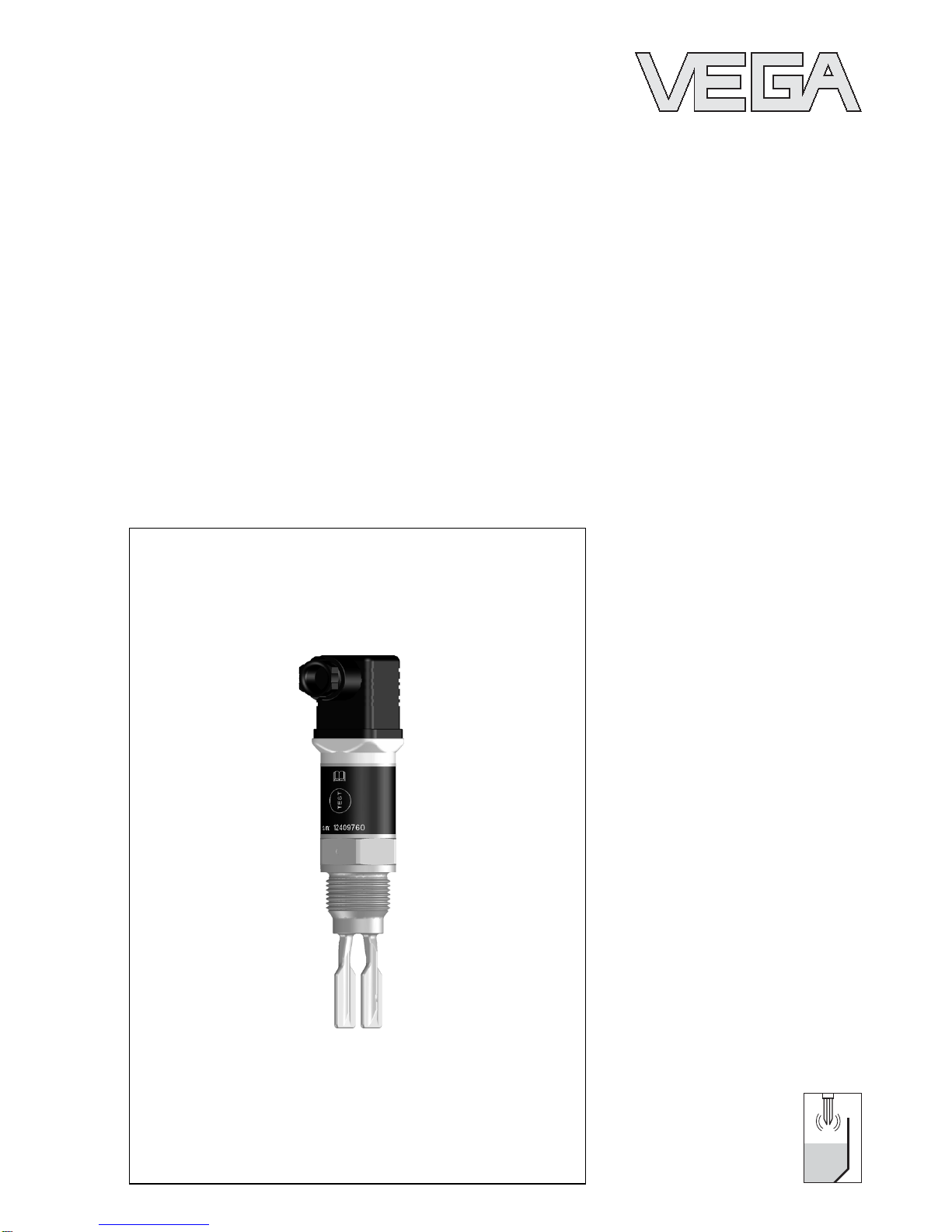
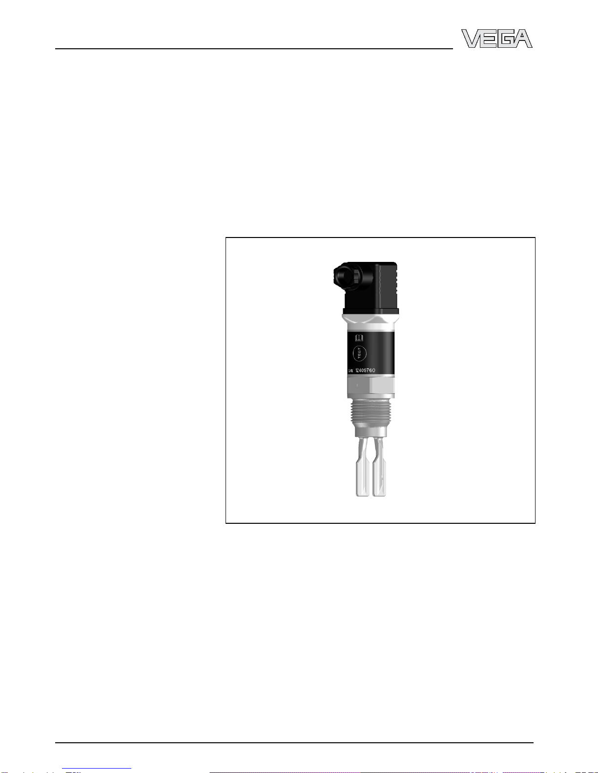
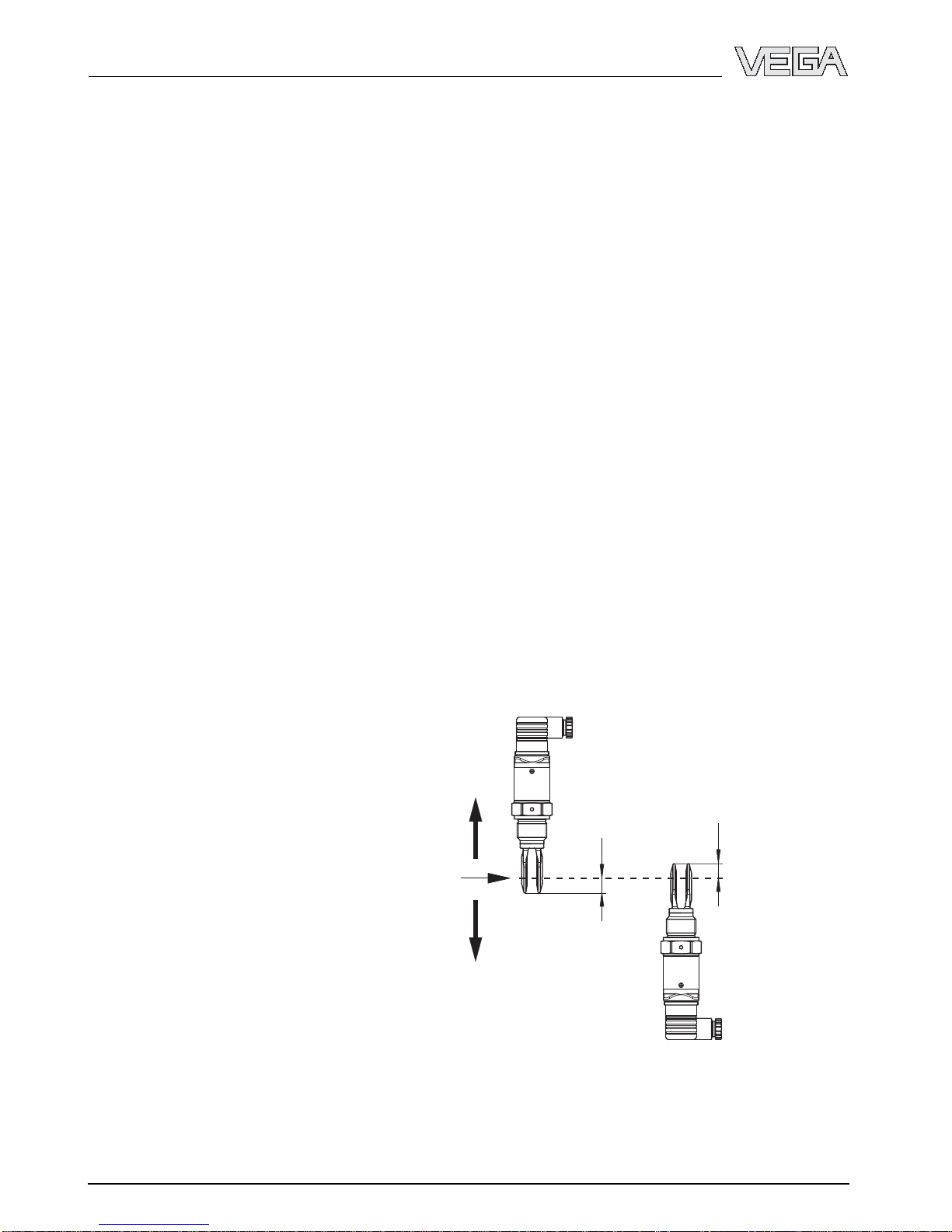
Vega VEGAVIB 62 Installation instructions

Vega
Vega POINTRAC 31 User manual

Vega
Vega VEGAPULS 61 User manual

Vega
Vega VEGAPULS WL 61 User manual

Vega
Vega VEGACAL 62 User manual

Vega
Vega VEGAWAVE Wiring diagram

Vega
Vega VEGACAL 66 User manual