Veit Brisay VEIT 2305 User manual

TD2305_i20081001.doc
Betriebsanleitung
Operating Instructions
Dampferzeuger Hodamat
VEIT 2305
Hodamat Steam Generator
Pressing for Excellence

Dampferzeuger Hodamat VEIT 2305
VEIT 2305 Hodamat Steam Generator
01.10.2008 2
VEIT GmbH
Justus-von-Liebig-Str. 15
D - 86899 Landsberg am Lech
Germany
Phone +49 (81 91) 479 0
Fax +49 (81 91) 479 149
www.veit-group.com
Service Hotline
Germany: +49 (81 91) 479 133
Europe: +49 (81 91) 479 252
America: +1 (770) 868 8060
Asia: +852 2111 9795
Ersatzteile/Spare Parts
Vertrieb/Sales +49 (8191) 479 176
Vertrieb Textilpflege/ +49 (8191) 479 129
Sales Textile care

Dampferzeuger Hodamat VEIT 2305
VEIT 2305 Hodamat Steam Generator
01.10.2008 3
Inhaltsverzeichnis / Table of Contents:
1Warnhinweise / Warnings 4
2Sicherheitshinweise für die Arbeit mit dem
Dampferzeuger VEIT 2305 / Safety Instructions for
working with the Steam Generator VEIT 2305 4
3Betriebsanleitung / Operating Instructions 5
3.1 Technische Daten / Technical Data 6
Artikelnummer 7
Elektrischer Anschluss 7
Maße und Gewichte 7
3.1.1 Kesselinhalt / Boiler Capacity 8
3.1.2 Heizleistung und Anschlusswert / Heating Power and Connected Load 8
3.1.3 Anheizzeit / Heating-Up Time 8
3.1.4 Dampf und Druck / Steam and Pressure 8
3.2 Aufstellung / Installation 8
3.3 Vor Inbetriebnahme der Dampferzeuger / Prior to Commissioning the Steam Generator 9
3.4 Befüllung / Filling 9
3.5 Nachfüllen während des Betriebes / In-Operation Refilling 10
3.6 Außerbetriebnahme / Shut-Down 10
3.7 Kesselreinigung (Abschlämmung) / Boiler Cleaning and Blow-down 10
3.7.1 Sicherheitshinweise / Safety Instructions 10
3.7.2 Abschlämmen / Blow-down 11
3.8 Weitere Funktionen und Sicherheitseinrichtungen / Further Functions and Safety Features 12
3.9 Wartung und Plege / Maintenance and Service 13
4Ersatzteile Dampferzeuger Hodamat / Spare Parts
Steam Generator Hodamat 14
4.1 Zeichnungen / Drawings 14
4.2 Ersatzteilliste / Spare Parts List 18
5Ersatzteile SEM-Pumpe / Spare Parts SEM-Pump 20
6Merkblatt 2305-007 / Information Leaflet 2305-007 21
7Stückliste zu Schaltplan 2305 / Parts List for Circuit
Diagram 22
8Schaltpläne / Circuit Diagrams 24
9Aufbau der Ergänzung von Klemmleiste X5 /
Assembling of complement strip terminal X5 28
10 Service- und Pflegeanleitung / Service and
Maintenance Instructions 29
11 EG-Konformitätserklärung / EC Declaration of
Conformity 32

Dampferzeuger Hodamat VEIT 2305
VEIT 2305 Hodamat Steam Generator
01.10.2008 4
1 Warnhinweise / Warnings
STÖRUNGEN AN DER ELEKTRISCHEN ANLAGE
DÜRFEN NUR DURCH ELEKTROFACHKRÄFTE
BEHOBEN WERDEN.
VOR ÖFFNEN DES GERÄTES HAUPTSCHALTER IN
STELLUNG „0“ BRINGEN UND NETZSTECKER ZIEHEN.
IM GEFAHRENFALL NETZSTECKER ZIEHEN!
DIE ABSCHLÄMMUNG DARF NUR DURCH
EINGEWIESENES PERSONAL UND NUR UNTER
EINHALTUNG DER VORGESCHRIEBENEN
SICHERHEITSHINWEISE ERFOLGEN.
NACH DEM ABSCHLÄMMEN MUSS DER
ABSCHLÄMMHAHN MIT DEM SICHERHEITSBÜGEL
VERRIEGELT WERDEN.
BEI VERWENDUNG VON SCHWIMMERBEHÄLTERN;
DIESE NICHT UNBEAUFSICHTIGT BETREIBEN.
IN BETRIEBSPAUSEN ABSPERRHAHN SCHLIESSEN.
DAS GERÄT VOR FROST SCHÜTZEN.
ELECTRICAL FAULTS MUST ONLY BE REPAIRED BY
AUTHORIZED PERSONNEL.
BEFORE OPENING THE MACHINE SET THE MAIN SWITCH
TO POSITION "0" AND DISCONNECT.
IN CASE OF EMERGENCY PULL THE MAINS PLUG.
BLOW-DOWN MUST ONLY BE PERFORMED BY TRAINED
PERSONNEL AND ONLY BY FOLLOWING THE STIPULATED
SAFETY INSTRUCTIONS.
THE BLOW-DOWN BALL VALVE HAS TO BE LOCKED WITH
THE SAFETY BOW AFTER-BLOW-DOWN.
WHEN USING FLOAT TANKS, DON’T OPERATE THIS
UNATTENDED
DURING OPERATION BRAKE CLOSE THE STOP COCK
PROTECT THE UNIT FROM FROST.
2 Sicherheitshinweise für die Arbeit mit dem Dampferzeuger VEIT 2305 / Safety
Instructions for working with the Steam Generator VEIT 2305
Der Dampferzeuger ist ausschließlich für die Erzeugung von
Dampf zur Verwendung in Bügelgeräten und Detachierpistolen
konzipiert.
Der Dampferzeuger ist für den Betrieb mit normalem oder
enthärtetem Leitungswasser geeignet. Der Zusatz des
Kalkbindemittels Lapidon in der in Abschnitt 3.7.2 genannten
Dosierung ist zulässig. Bei Zusatz anderer Chemikalien
übernimmt VEIT keine Haftung für Funktion und Sicherheit des
Geräts.
Bei der Aufstellung des Dampferzeugers muss sichergestellt
werden, dass
•der Abschlämmhahn auf der Geräterückseite nicht
versehentlich geöffnet werden kann
•Anschlusskabel, Abschlämmschlauch und
Abschlämmbehälter keine Stolperfallen darstellen
•Dampfventile und Sicherheitsventil nicht zufällig berührt
werden können.
Dampfschläuche vor Arbeitsbeginn auf Beschädigungen
überprüfen. Abgenutzte oder versprödete Schläuche umgehend
ersetzen.
Dampfventile nicht berühren. Verbrennungsgefahr!
Dampfstrahl nicht auf Personen richten. Verbrennungs- und
Verbrühungsgefahr!
Dampfstrahl nicht gegen Gerät richten. Gefahr von Schäden in
der Elektrik!
Beim Abschlämmen sorgfältig vorgehen. Verbrühungsgefahr!
Zur Durchführung des sicheren Abschlämmens unbedingt die
Anleitung in Abschnitt 3.7.2 sowie die Sicherheitshinweise in
Abschnitt 3.7.1 dieser Betriebsanleitung befolgen.
Wenn Dampf aus dem Gerät austritt, sofort Gerät stillsetzen und
Leck fachgerecht beheben lassen.
Bitte beachten Sie die Wartungshinweise in Abschnitt 3.9 dieser
Anleitung.
The steam generator is exclusively designed for the production
of steam for the use in ironing units and spotting pistols.
The steam generator is suited for operation with normal or
softened tap water. The addition of the decalcifying agent
Lapidon is allowed, as described under section 3.7.2. If other
chemicals are added, VEIT bears no responsibility for any
resulting damage and for the function and safety of the machine.
During the installation of the steam generator the following points
have to be ensured:
•the blow-down ball valve and the vent valve on the back
side of the unit cannot be inadvertently opened.
•the connection cable, blow-down hose and blow-down tank
cannot be tripped over.
•the steam valve and the safety valve cannot be accidentally
touched.
Check the steam hose for damage before use. Replace worn
and brittle hose immediately.
Do not touch steam valve. Danger of burning and scalding!
Do not point steam jet at people. Danger of burning and
scalding!
Do not point steam jet at machine. Danger of damage to the
electrics!
Proceed with care when blowing-down. Danger of scalding!
Please following closely the instructions in section 3.7.2 as well
as the safety instructions in section 3.7.1 of these operating
instructions to ensure safe blow-down.
If steam escapes from the unit, shut down the machine
immediately and have the leak repaired by a specialist.
Please pay attention to chapter 3.9 maintenance and service of
these operating instructions.

Dampferzeuger Hodamat VEIT 2305
VEIT 2305 Hodamat Steam Generator
01.10.2008 5
3 Betriebsanleitung / Operating Instructions
08 Betriebsschalter
09 Betriebsstundenzähler
10 Manometer kpl.
12 Minimalkontroll-Lampe rot
13 Minimalkontroll-Lampe weiß
14 Schiebeschalter für Dampfbügler links und rechts
14a Entlüftungsschalter
16 Abschlämmschlauch mit Diffusor
17 Abschlämmventil mit Sicherheitsventil
18 Laufrollen
19 Ansaugfilter kpl.
20 Befüllschlauch
22 SEM-Pumpe
24 Dampfventil m. Drosselschraube
25 Entlüftungsventil
27 Plastikgriff
29 Spezialkleinsteckdose
31 Sicherheitsventil
50 Speisewasserbehälter
51 Wasseranschlussnippel (wenn Behälter mit
Schwimmerventil Art. Nr. 423 038 002 0)
52 CEKON-Stecker
53 Überdruckabblasrohr
08 Main switch
09 Working hour meter
10 Pressure gauge, cpl.
12 Min. level indicator, red
13 Max. level indicator, white
14 Slide switch, l/r steam iron
14a Venting switch
16 Blow-down hose (must be attached)
17 Blow-down valve
18 Casters
19 Suction filter, cpl.
20 Filling hose
22 SEM pump
24 Steam valve w. throttle screw
25 Venting valve
27 Plastic handle, cpl.
29 Special socket
31 Safety valve (relief valve)
50 Feedwater tank
51 Water connection nipple(if fitted with
float tank Art. No. 423 038 002 0)
52 Cekon-plug
53 Pressure release tube

Dampferzeuger Hodamat VEIT 2305
VEIT 2305 Hodamat Steam Generator
01.10.2008 6
3.1 Technische Daten / Technical Data

Dampferzeuger Hodamat VEIT 2305
VEIT 2305 Hodamat Steam Generator
01.10.2008 7
Modell VEIT 2305
4,5 kW VEIT 2305
6,0 kW
Artikelnummer 1230510010 1230510020
Elektrischer Anschluss
Volt 400 400
Hz 50-60 50-60
kW 4,5 6,0
A
Netzseitige Absicherung
Wasseranschluss 30 l Tank 30 l Tank
Dampfanschluss Zoll 1/2 1/2
Betriebsdruck bar 4,0 4,0
Einstellbar auf bar max. 5,0 max. 5,0
Dampfmenge kg/h 5,8 7,8
Dampfverbraucher 2 Bügler 2 Bügler
Maße und Gewichte
Breite mm 465 465
Höhe mm 1050 1050
Tiefe mm 550 550
Gewicht kg 74 74
Model VEIT 2305
4.5 kW VEIT 2305
6.0 kW
Article number 1230510010 1230510020
Electrical Connection
Volt 400 400
Hz 50-60 50-60
kW 4.5 6.0
A
Fuse protection
Water connection 30 l Tank 30 l Tank
Steam connection inch 1/2 1/2
Working pressure bar 4.0 4.0
Adjustable to bar max. 5.0 max. 5.0
Steam output kg/h 5.8 7.8
Steam user 2 irons 2 irons
Dimensions and weight
Width mm / inch 465 / 18 465 / 18
Height mm / inch 1050 / 41 1050 / 41
Depth mm / inch 550 / 22 550 / 22
Weight kg / lbs 74 / 163 74 / 163
Anschluss-Stellen 2 Connection points 2
Speisewasserbehälter 30 Liter Feedwater tank 30 l

Dampferzeuger Hodamat VEIT 2305
VEIT 2305 Hodamat Steam Generator
01.10.2008 8
3.1.1 Kesselinhalt / Boiler Capacity
Wasserinhalt 8,8 Liter NW / 9,3 Liter HW Water volume 8.8 l min. water level /9.3 l
max. water level
Kesselvolumen 15 Liter Boiler capacity 15 l
3.1.2 Heizleistung und Anschlusswert / Heating Power and Connected Load
4500 Watt / 6000 Watt 4500 W / 6000 W
mit 2 HD-Bügeleisen ca. 7000 Watt / 8500 Watt if fitted with 2 HP irons 7000 W / 8500 W approx.
Anschluss 220/380 Volt Drehstrom
Mittelleiter und Schutzleiter
nach VDE getrennt
Power Supply 220/380 V Three-phase current
neutral wire and earth
separated according to VDE
regulations
3.1.3 Anheizzeit / Heating-Up Time
ca. 15 Minuten approx. 15 minutes
3.1.4 Dampf und Druck / Steam and Pressure
Normarbeitsdruck 3,5 - 4 bar Normal operating pressure 3.5 - 4 bars
zul. Betriebsüberdruck 6 bar Admissible design pressure 6.0 bars
Dampftemperatur bei 3,5 - 4
bar 147 - 151°C Steam temperature at 3.5-4
bars 147 - 151°C
Dampfleistung ca. 5,8 kg/h / 7,8 kg/h Steam capacity approx. 5.8 kgs/h - 7.8 kgs/h
VEIT 2305 mobiler Dampferzeuger auf Laufrollen mit
vollautomatischer, elektronischer Steuerung.
Speisewasserbefüllung aus Speisewasserbehälter (50) mit
selbstansaugender Elektro-Membranpumpe (22) elektronisch
gesteuert.
VEIT 2305 mobile steam generator on casters, equipped with a
full automatic, electronic control system. Filling by feedwater tank
(50) with a self-priming electric membrane pump (22),
electronically controlled.
3.2 Aufstellung / Installation
Nachdem das Gerät aus der Verpackung genommen wurde,
werden die inliegenden Laufrollen (18) montiert. Die Handgriffe
(27) ermöglichen leichten Transport und Mobilität.
After unpacking the steam generator the enclosed rollers (18)
have to be fitted. Transport and mobility with effortless ease (27).

Dampferzeuger Hodamat VEIT 2305
VEIT 2305 Hodamat Steam Generator
01.10.2008 9
3.3 Vor Inbetriebnahme der Dampferzeuger / Prior to Commissioning the Steam Generator
Achtung!
Wer Änderungen am Gerätestecker (CEKON-Stecker) vornimmt
oder ihn durch einen anderen Stecker ersetzt, haftet für die
richtige Klemmung der einzelnen Kabeladern und etwaige
nachteilige Folgen.
Die einzelnen Adern des Gerätekabels sind nach den
europäischen Bestimmungen in ihrer Funktion wie folgt:
blau = Mittelleiter
grün/gelb = Schutzleiter
schwarz = Phasen L1 + L3
braun = Phase L2
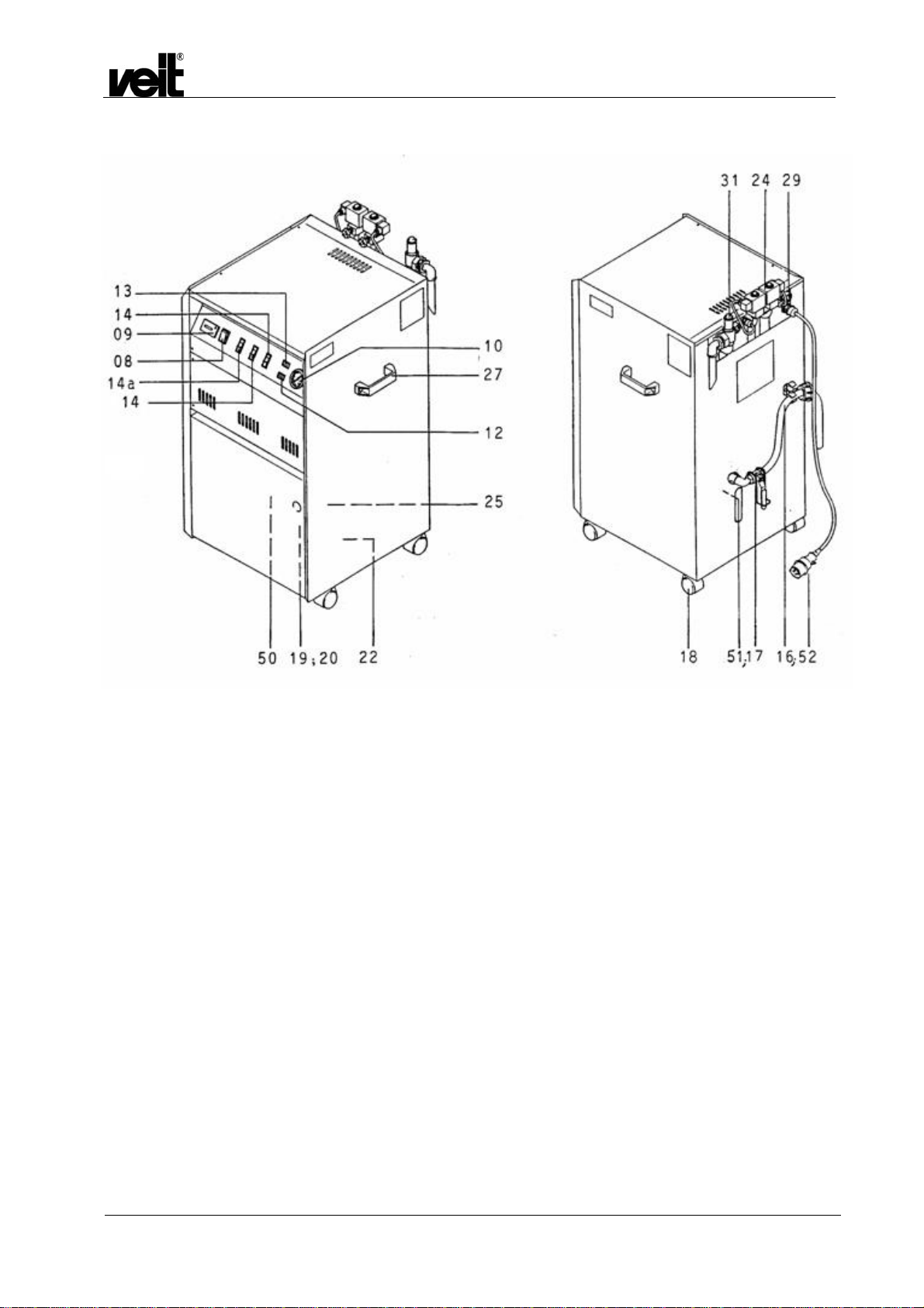
Bitte prüfen Sie, ob Steckdose mit der Funktion der einzelnen
Kabeladern des CEKON-Steckers (52) übereinstimmt. Vor
Inbetriebnahme werden die Hochdruckdampfbügler am Gerät
angeschlossen. Hochdruckdampfschlauch mit Verschraubung
3/8" an Dampfventil (24) rückseitig am Gerät anschließen.
Ebenso Anschlusskabel mit Spezialkleinstecker an
Spezialkleinsteckdose (29) anschließen. Befüllschlauch (20) bis
zum Boden des Speisewasserbehälters (50) einlegen.
Caution!
Care must be taken to wire up and plug correctly to avoid serious
consequences. On modification or replacement of device plug
you are fully responsible for correct clamping.
Wiring according to European Specifications:
blue = neutral
green/yellow = earth
black = phases L1 + L3
brown = phase L2
Please check whether the terminals of the Cekon outlet coincide
with the function of individual leads terminated on Cekon-type
plug (52). Prior to commissioning, connect the high-pressure
steam irons to the system. Use 3/8" fitting to connect up high-
pressure steam hose to steam throttle (24) at the rear wall of the
unit. Moreover, use special miniature plug to connect cable up to
special miniature socket (29). Insert refilling hose (20) until it
touches the bottom of feedwater tank (50).
3.4 Befüllung / Filling
Der Dampferzeuger DE 2305 ist ab Werk mit einem
Vorratsbehälter ausgestattet, der manuell befüllt wird.
Optional kann auch ein Wasserbehälter mit Schwimmer (Art.nr.
4230380020) verwendet werden.
Für direkten Anschluss an die Wasserleitung ist dieser
Dampferzeuger nicht vorgesehen.
Wenn das Gerät mit einem Speisewasserbehälter mit
Schwimmer ausgerüstet ist (gesondert bestellt), wird es über den
Hochdruckschlauch und rückseitigen Nippel (51) an die
Wasserleitung angeschlossen. Über den im Gerät eingebauten
Speisewasserbehälter mit oder ohne Schwimmer wird somit die
Wasserversorgung gewährleistet.
Bitte beachten Sie das Merkblatt IL2365-004, das dem
Schwimmerbehälter beiliegt!
Betriebsschalter (08) und Entlüftungsschalter (14a) einschalten.
Minimalkontroll-Lampe rot (12) leuchtet auf. Die Membranpumpe
(22) befüllt jetzt automatisch den Kessel bis zur Maximalstufe.
Die Kontroll-Lampe rot erlischt und die Maximalkontroll-Lampe
weiß (13) leuchtet auf. Gleichzeitig schaltet sich die
Kesselheizung ein. Entlüftungsschalter (14a) nach ca. 5 Minuten
schließen. Nach weiteren 8 Minuten zeigt sich am Manometer
(10) ein Druck von ca. 2 bar. Die beiden Schiebeschalter (14) für
Dampfbügler links und rechts werden eingeschaltet. Nach
Erreichen des Betriebsdruckes von 3,5 bar ist das Gerät
betriebsbereit.
Die erforderliche Dampfmenge kann mit der Drosselschraube
am Dampfventil (24) stufenlos eingestellt werden.
The steam generator DE 2305 is equipped ex factory with a
holding tank, which is filled manually.
Optionally also a water tank with float (art. No. 4230380020) can
be used.
This steam generator is not intended for direct connection to the
water pipe.
If the unit is fitted with a feedwater tank featuring a float (as per
separate order), connect the unit via the high-pressure hose and
the rear-wall nipple (51) to the water mains.
Please attend the information leaflet IL_2365-004, which is
attached to the float tank!
Switch on main switch (08) and air-vent switch (14a).
Red minimum level indicator (12) will light up. Now, the
membrane pump (22) will automatically fill the tank until the
maximum water level has been reached. This will cause the red
indicator to go off, and white maximum level indicator (13) to
come on. Simultaneously, the boiler heating system will be
switched on.
After approx. 5 minutes, close venting switch (14a).
After another 8 minutes, pressure gauge (10) will indicate a
pressure of approx. 2 bars. Switch on the two (14) slide switches
for left and right-hand steam irons. Once the operating pressure
of 3.5 bars has been reached, the unit will be ready for
operation.
Steam quantity is infinitely adjustable at throttle screw at the
steam valve (24).

Dampferzeuger Hodamat VEIT 2305
VEIT 2305 Hodamat Steam Generator
01.10.2008 10
3.5 Nachfüllen während des Betriebes / In-Operation Refilling
Während des Betriebes füllt sich der Kessel des
Dampferzeugers automatisch. Sinkt der Wasserspiegel durch
Dampfverbrauch auf die Minimalstufe ab, so wird die
elektronische Niveauregelung die Befüllung in Funktion setzen,
(Membranpumpe (22) und elektromagnetisches Befüllventil).
Optische Funktion der Kontroll-Lampen wie vorher beschrieben.
Achtung!
Der Entlüftungsschalter (14a) darf während des Betriebes nicht
betätigt werden.
Sollte die Membranpumpe ungewöhnlich lange laut laufen, so ist
der Speisewasserbehälter leer oder der Schmutzfänger
verschmutzt.
Sollten im Ansaugschlauch Luftblasen sichtbar sein, so ist hierzu
das Entlüftungsventil (25) mit dem anhängenden Schlüssel
während des Pumpens zu öffnen und nach Wasseraustritt
wieder zu schließen. Sollte die Membranpumpe kein Wasser
fördern, so liegt Haftungseffekt beim Ansaugventil vor. Zum
Beheben bitte kurz mit Druckluft in den Ansaugstutzen der
Pumpe blasen. (Den Haftungseffekt kann man auch durch einen
kurzen Anschluss des Ansaugventils an die Wasserleitung
beheben.)
During operation, the boiler will be refilled automatically.
Whenever steam consumption makes the water level drop to its
minimum position, the electronic level control system will trigger
the refilling function (membrane pump (22) and electromagnetic
refilling valve).
Visual controls via indicators, as described above.
Caution!
Never actuate venting switch (14a) during operation.
Whenever pump is running noisily for an unusually long period of
time, the feedwater tank will be empty or the dirt trap will be
clogged.
Should there be any bubbles within the suction hose, open
venting valve (25), using the key attached to it, while the pump is
running; once water appears, close the valve.
If the membrane pump does not deliver any water, there will be
magnetic adhesion. Briefly blow compressed air into suction
sleeve of pump or connect suction valve to water conduit for a
short moment.
3.6 Außerbetriebnahme / Shut-Down
Alle Schalter (08, 14) ausschalten.
Achtung!
Nach Arbeitsende ist unbedingt der Wasserzulauf zu schließen.
Switch off all switches (8,14).
Caution!
When stopping work, it will be essential to shut off the water
supply.
3.7 Kesselreinigung (Abschlämmung) / Boiler Cleaning and Blow-down
3.7.1 Sicherheitshinweise / Safety Instructions
Achtung: Unsachgemäßes Abschlämmen bedeutet
Verbrühungsgefahr!
Folgende Sicherheitsmaßnahmen müssen vor jedem
Abschlämmen kontrolliert werden:
•der Abschlämmbehälter muss bis zur Markierung mit
kaltem Wasser gefüllt sein
•der Deckel des Abschlämmbehälters muss zwischen den
beiden Edelstahlschellen fixiert sein
•die Löcher des Diffusors müssen frei von
Kalkablagerungen sein
•der Deckel muss fest auf dem Behälter aufgeschraubt sein
•die Entlüftungsbohrungen des Abschlämmbehälters
müssen frei sein
•der Abschlämmkugelhahn muss langsam geöffnet werden
Inexpert blow-down may cause burning!
Note the following safety instructions before the blow-down:
•The blow-down tank must be filled with cold water up to the
mark.
•The lid of the blow-down tank must be fastened between
the two stainless steel clamps.
•The length of the blow-down hose from the lid to the end of
the diffuser must be approx. 380 mm.
•The holes of the diffuser must not be covered by furring.
•The lid must tightly be screwed on the tank.
•The vent holes of the blow-down tank have not to be
covered by deposits.

Dampferzeuger Hodamat VEIT 2305
VEIT 2305 Hodamat Steam Generator
01.10.2008 11
Nach dem Abschlämmen:
•muss der Kugelhahn sofort wieder geschlossen werden,
da sonst durch Unterdruckbildung im Kessel das
Abschlämmwasser wieder angesaugt wird
•muss unbedingt der Kugelhahn mit dem Sicherheitsbügel
verriegelt werden
•The blow-down ball valve must slowly be opened.
After blow-down:
•The blow-down ball valve must be closed immediately.
Otherwise the water will be sucked in again by the vacuum
in the boiler.
•The blow-down ball valve has to be locked tightly with the
safety bow.
3.7.2 Abschlämmen / Blow-down
Alle Schalter (08, 14) ausschalten. Wasserversorgung schließen.
Der zusätzliche Abschlämmbehälter hat links und rechts des
Einfüllstutzens zwei Entlüftungslöcher.
Der Behälter muss bis zur Markierung mit kaltem Wasser gefüllt
sein. Er wird flachgelegt (siehe Skizze). Der Schraubverschluss
wird bis an die Schlauchklemme herangezogen. Das
Schlauchende wird in den Abschlämmbehälter eingeführt und
der Schraubverschluss fest verschraubt. Es muss sichergestellt
sein, dass der Schlauch nicht aus dem Schraubverschluss
herausgezogen werden kann.
Das Abschlämmventil (17) wird ganz geöffnet. Dadurch ist
gewährleistet, dass Kalkablagerungen voll ausströmen. Der
ebenfalls dabei ausströmende Dampf kondensiert im kalten
Wasser.
Switch all switches (8, 14) off. Shut off water supply.
The additional drainage tank features two venting holes, one
each to either side of the connection.
Fill cold water into this tank up to the marking indicated. Place it
so that it is wider than high (see drawing). Pull the threaded plug
up to the hose clamp. Introduce the hose end into the drainage
tank and screw down the threaded plug. Make sure that the hose
cannot be pulled out of the screwed connection.
Fully open blow-down valve (17). This will guarantee that any
scale deposits are flushed out of the unit. Any steam coming out
simultaneously will condense within the cold water.
Achtung!
Der Abschlämmschlauch muss unbedingt am oder im
Abschlämmbehälter befestigt sein (Schlauchklemme).
Caution!
The blow-down hose must be attached to or within the
drainage tank (jubilee clip).
Nach kurzer Zeit ist der Dampfkessel leer.
Die Manometernadel zeigt keinen Druck mehr an.
Unbedingt den Abschlämmbehälter mit dem Sicherheitsbügel
verriegeln.
Das Abschlämmwasser wird weggegossen.
Danach Abschlämmbehälter wieder befüllen; aus
Sicherheitsgründen den Abschlämmschlauch in den Behälter
schieben und Schraubverschluss fest verschrauben.
Es empfiehlt sich, bei hartem Wasser die Abschlämmung jeden
Tag vorzunehmen. Nach Schließen des Abschlämmventils (17)
wird das Gerät sofort wieder befüllt.
Der im Wasser enthaltene Kalk kann zu Ablagerungen im Kessel
und auf den Heizungen führen und Ausfälle hervorrufen. Um
dies zu vermeiden, empfehlen wir ab einer Wasserhärte von
5°dH das Kalkbindemittel Lapidon zu verwenden. Das
Kalkbindemittel bewirkt, dass der im Wasser enthaltene Kalk
gebunden wird und als Schlamm beim Abschlämmen aus dem
Kessel entfernt wird.
Bei einer Wasserhärte von 10°dH bis 15°dH wird
für ca. 10 l Wasser eine halbe Dosierkappe des
mitgelieferten Kalkbindemittels Lapidon
beigegeben. Werden 15°dH überschritten muss
After a short period of time, the boiler will be empty, and the
gauge needle will show zero pressure.
The blow-down ball valve has to be locked tightly with the safety
bow.
Pour away all the discharge.
Afterwards the blow-down tank has to be refilled again and for
safety reasons push the blow-down hose into the tank and screw
down closely the screw plug.
If you have to operate on hard water, daily blow-down is to be
recommended.
As soon as blow-down valve (17) is closed again, the unit will be
refilled.
The water contains chemicals which may fur the boiler and the
heating elements and may cause malfunctions.
If the water hardness exceeds 5°dH (degrees German
hardness), please use the decalcifying agent Lapidon. This
agent binds the fur and scale deposits contained in the water,
which can be removed from the boiler as sludge during blow-
down.
If the water hardness is between 10°dH and 15°dH, add half a
cap of the decalcifying agent Lapidon for approx. 10 l of water. If
cold water up to the
mark

Dampferzeuger Hodamat VEIT 2305
VEIT 2305 Hodamat Steam Generator
01.10.2008 12
eine ganze Dosierkappe für ca. 10 l Wasser
beigefügt werden.
Zu große Mengen Lapidon führen zum Schäumen des
Kesselwassers und Rückstände von Lapidon werden im Dampf
mitgeführt.
Achtung!
Bei Verwendung einer Enthärtungsanlage, z.B. VEIT-Wafi,
entfällt die Verwendung von Lapidon. Allerdings muss die
Abschlämmung auch hierbei unbedingt durchgeführt werden.
the water is harder than 15°dH, add a whole cap for approx. 10 l
of water.
Excessive use of Lapidon will cause foaming of the boiler water
and residues of Lapidon are contained in the steam.
Caution!
When using water softening equipment such as VEIT Wafi, there
is no need to employ any Lapidon. However, blow-down will
remain necessary.
3.8 Weitere Funktionen und Sicherheitseinrichtungen / Further Functions and Safety Features
Zu Servicezwecken werden der obere und der vordere
Gerätedeckel abgenommen.
1. Das Sicherheitsventil (bauteilgeprüft) (31) dient als erstes
Sicherheitselement dazu, evtl. auftretenden, höheren
Dampfdruck abzublasen.
Hierbei tritt Dampf am Überdruckabblasrohr (53) aus.
Achtung!
Die Technischen Regeln für Dampfkessel (TRD 421) schreiben
vor, dass Sicherheitsventile entlastbar sein müssen. Deshalb:
1 bis 2 x jährlich Funktionsprüfung des Sicherheitsventils. Dazu
Griffkappe nach links drehen bis Rastung spürbar.
Das Gerät soll dabei unter Dampfdruck stehen.
2. Als zweites Sicherheitselement ist oben der Druckregler
(Pressostat) eingebaut. Dieser steuert den am Manometer
angezeigten Dampfdruck.
3. Als drittes Sicherheitselement ist zwischen den
Messelektroden der Temperaturbegrenzer Heatstop
montiert.
Durch diese TÜV-bauteilgeprüfte Einrichtung ist absoluter
Geräteschutz gewährleistet.
Achtung!
Dieses Element muss nach evtl. Defekt ausgetauscht werden,
nachdem die Defektursache beseitigt ist. Ein Ersatzelement
befindet sich im Gerät.
4. Im stirnseitigen Geräteteil befindet sich die elektrische und
elektronische Steuerung.
5. Zum Schutz der Elektronik ist hierin ein Sicherungselement
eingebaut.
Eine Ersatzsicherung befindet sich angeklebt nebenliegend.
6. Im vorderen Geräteteil befindet sich die Befüllgruppe. Hierin
dienen Elektromagnetventil und Rückschlagventil als
weitere Sicherheitselemente.
Detachable front and top lid for service purpose.
1. The first safety element permitting any increased steam
pressure to blow off is safety valve (31) (featuring design
approval).
If this valve is actuated, steam will be bled off via pressure
outlet tube (53).
Caution!
The TRD 421 rules and regulations covering boilers provide for
safety-valve pressure relief. Therefore:
check the safety valve 1 - 2 x annually for proper functioning. To
do so, turn the handle cap leftwards until it latches.
During the process, the unit may (but is not required to) be under
steam pressure.
2. The second safety element is provided by the (Pressostat-
type) pressure controller installed on top. This device
controls the steam pressure as displayed by the gauge.
3. The third safety element provided is the heatstop-type
temperature limiter installed between the measuring
electrodes.
Thanks to this safety feature approved by TÜV (German
Technical Examination Association) the unit may be
guaranteed to be safe.
Caution!
It may be necessary to remove this system whenever any defect
has been repaired. A replacement system is located within the
unit.
4. The front section of the unit houses all electric and
electronic controls.
5. To protect the electronic systems, there is a built-in safety
fuse.
Next to it, a replacement fuse is taped down on to the
system.
6. The front unit section houses, moreover, the refilling
system.
Solenoid and check valves provide additional security.
Weitere Sicherheitselemente sind: Further features providing security are:

Dampferzeuger Hodamat VEIT 2305
VEIT 2305 Hodamat Steam Generator
01.10.2008 13
7. Edelstahlheizpatrone
8. Sicherungsbügel für Abschlämmhahn
9. Röhrenfedermanometer
7. Stainless-steel heating cartridge
8. Safety latch for block-down cock
9. Spring pressure gauge
3.9 Wartung und Plege / Maintenance and Service
Täglich:
•Kessel abschlämmen.
•Kontrolle des Abschlämmschlauches und des
Abschlämmbehälters wie unter 3.7.1 beschrieben.
•Die Dichtheit der Kugelhähne überprüfen.
•Die Funktion des Manometers und Druckreglers
überprüfen.
Daily:
•Drain the boiler.
•Check the blow-down hose and the blow-down tank as
described under chapter 3.7.1.
•Check all ball valves for leakage.
•Inspect the function of the manometer and the pressure
regulator.
Jährlich oder halbjährlich:
•Die Funktion des Sicherheitsventils muss durch
Anlüften (dazu die Kappe des Sicherheitsventils nach
links drehen) geprüft werden. Der Kessel muss dazu
unter Druck stehen. Durch das Abblasrohr des
Sicherheitsventils muss Dampf nach außen strömen.
•Die Plunger in den Elektromagnetventilen auf Dichtheit
prüfen, ggfs. erneuern.
Once or twice a year:
•The function of the safety valve must be tested by
venting. To do so, turn the lid of the safety valve to the
left. The boiler must be under pressure. The steam
must escape through the vent-tube of the safety valve.
•Check the plungers in the solenoid valves for leakage,
if necessary replace it.
Jährlich:
•Alle Anschlüsse auf Dichtheit, Korrosion
(Befestigungsschellen) und Festigkeit kontrollieren.
•Alle Funktionsteile (Manometer, Druckregler,
Sicherheitsventil, Rückschlagventil) auf eine
einwandfreie Funktion prüfen.
•Zur Wartung des Kessels Heizungen bzw.
Blindstopfen ausbauen. Das Innere des Kessels, die
Elektrode und die Heizungen von Schmutz und
Kalkablagerungen reinigen.
•Den Befüll- und Abschlämmstutzen auf Kalkreste
kontrollieren und ggf. reinigen.
•Befüll- und Abschlämmleitung demontieren und
reinigen, korrodierte Teile erneuern.
•Sicherheitsventilgruppe und Dampfleitungen
demontieren und reinigen. Korrodierte Teile erneuern.
•Alle Schläuche auf Beschädigungen und
Undichtigkeiten überprüfen.
•Anschlusskabel auf Beschädigungen überprüfen.
Yearly:
•Check all the connections for leakage, corrosion
(fastening straps) and tightness.
•Check that all the functioning parts (manometer,
pressure regulator, stop valve, safety valve) work
properly.
•Remove the heating elements and/or blind plug for
maintaining the boiler. Remove any dirt and scale
deposits from the inside of the boiler, the electrodes
and the heating elements.
•Inspect the filling and the drainage plinth for any scale
deposits and clean if necessary.
•Disassemble the filling and drainage line and clean it,
replace corroded parts.
•Disassemble the safety valve group and the steam
lines and clean it. Replace corroded parts.
•Check all hoses for damages and leakiness.
•Check connecting cable for damages.

Dampferzeuger Hodamat VEIT 2305
VEIT 2305 Hodamat Steam Generator
01.10.2008 14
4 Ersatzteile Dampferzeuger Hodamat / Spare Parts Steam Generator Hodamat
4.1 Zeichnungen / Drawings

Dampferzeuger Hodamat VEIT 2305
VEIT 2305 Hodamat Steam Generator
01.10.2008 15

Dampferzeuger Hodamat VEIT 2305
VEIT 2305 Hodamat Steam Generator
01.10.2008 16
42
41

Dampferzeuger Hodamat VEIT 2305
VEIT 2305 Hodamat Steam Generator
01.10.2008 17
32**
32 •
43

Dampferzeuger Hodamat VEIT 2305
VEIT 2305 Hodamat Steam Generator
01.10.2008 18
4.2 Ersatzteilliste / Spare Parts List
Pos. Artikel-Nummer
Article Number
Benennung Designation
1230510010
1230530010
1230540010
1230510020
1230540020
Dampferzeuger Hodamat 4,5 kW / 400 V
Ab Fabr.-Nr. .......07
Dampferzeuger Hodamat 4,5 kW / 3x220 V
Ab Fabr.-Nr. .......05
Dampferzeuger Hodamat 4,5 kW / 440 V
Ab Fabr.-Nr. .......05
Dampferzeuger Hodamat 6,0 kW / 400 V
Ab Fabr.-Nr. .......07
Dampferzeuger Hodamat 6,0 kW / 440 V
Ab Fabr.-Nr. .......05
Hodamat steam generator 4.5 kW / 400 V
serial no. .....07 and above
Hodamat steam generator 4.5 kW / 3x220 V
serial no. …..05 and above
Hodamat steam generator 4.5 kW / 440 V
serial no. .....05 and above
Hodamat steam generator 6.0 kW / 400 V
serial no. .....07 and above
Hodamat steam generator 6.0 kW / 440 V
serial no. .....05 and above
01
02
03
04
05
07
08
09
10
11
12
13
14
15
16
17
18
19
20
21
22
23
4230550070
4441350220
4252350060
4230550050
4230560200
5851010010
4230550090
4791450010
9290950030
4231530040
4230530180
4430450010
4430450020
4230550030
9280152270
4230560080
4230160020
4310010730
4233040010
4230510170
4230580110
9270530040
4230560000
4230580290
4252350040
Luftschaltschütz 220 V / 50 Hz
Luftschaltschütz 240 V / 50 Hz
Sicherungsautomatik 20 A
Sicherung 0,63 A mittelträge / 250 V (10 Stück)
Trafo 220 V / 24 V 3 VA kurzschlusssicher
Sicherung 1 A / mittelträge / 10 Stück
Elektronik einzeln (steckbar)
Geräteschalter Wippe grün
Betriebsstundenzähler 220 V / 240 V / 50 Hz
Manometer 0 - 10 bar
Kupferschlange / Manometer
Kontroll-Lampe rot
Kontroll-Lampe weiß
Schiebeschalter mit Kontroll-Lampe (bis 09/08)
Schiebeschalter mit Kontroll-Lampe (ab 10/08)
Heizung 4,5 kW / 400 V mit Dichtung
Heizung 3,0 kW / 400 V mit Dichtung
Auslaufschlauch 1.000 mm ½“
Kugelhahn ½“
Rollensatz kpl. (4 Stück)
Ansaugfilter kpl.
Schlauch PVC mit Einlage Dm 6x3 (LM)
Anschlusskabel 4,2 m
SEM-Pumpe 220 V / 240 V / 50 Hz / 60 Hz
Relaissockel 11-polig
Air type contactor, 220 V / 50 Hz
Air type contactor, 240 V / 50 Hz
Safety cut-out 20 A
0.63 A / 250 V fuses, semi time lag (10 fuses)
Transformer 220 V/ 24 V, 3 VA short circuit-proof
Fuse 1 A /semi time-lag/10 pieces
Individual electronics system (pluggable)
Switch green
Working hour meter, 220 V / 240 V / 50 Hz
Pressure gauge 0-10 bar
Copper tube serpentine / pressure gauge
Red indicating lamp
White indicating lamp
Slide switch with indicating lamp (until 09/08)
Slide switch with indicating lamp (from 10/08)
Heating element 4.5 kW / 400 V with sealing
Heating element 3.0 kW / 400 V with sealing
Outlet hose 1000 mm, 1/2"
Ball cock, 1/2"
Set of rolls, cpl. (4 pieces)
Suction filter, cpl.
PVC hose diameter 6x3 with layer (r. m.)
Connection cable 4.2 m
SEM pump 220 V / 240 V, 50 Hz / 60 Hz
Relay header 11-score

Dampferzeuger Hodamat VEIT 2305
VEIT 2305 Hodamat Steam Generator
01.10.2008 19
Pos. Artikel-Nummer
Article Number
Benennung Designation
24
25
26
27
28
29
30
31
32
32**
33
34
35
36
37
38
39
40
41
42
43
9290650180
423323018G
4283210000
4233230130
4231270030
4310020190
4230520120
423058013G
4400000370
4230540230
9290650110
9290650440
4230560110
4230535060
2221701000
9290650590
9230350140
9230350160
9230350170
9230350290
9230350300
9230350130
9410910520
2140110170
4231230120
EMV I NW 2,8 200-254 V / 50-60 Hz
Plunger kpl. (3 Stück)
Spule 200-254 V / 50-60 Hz
Stopfbuchse mit Spindel und Dichtung
Entlüftungshahn ¼“
Rückschlagventil 3/8“
Plastikgriff kpl.
Elektroden kpl.
Spezialeinsteckdose spezial 4-polig
Druckwächter
Sicherheitsventil 6 bar ½“
Sicherheitstemperaturbegrenzer ab Fabrikations-
Nummer ........07
Temperaturbegrenzer Heatstop bis Fabrikations-
Nummer ........06
Dampfkessel
Lapidon 1 Karton à 4 Flaschen
Überdruckventil
Klemme EK 2,5/35 gnge
Klemme EK 6/35 gnge
Klemme SAK 6/35
Klemme DK 4QV/35
Klemme DK 4Q/35
Klemme ASK 1/35 für Sicherung 0,63 A
Winkelverschraubung ½“ I-I Zu
Panzerschlauch 3/8“x350
Panzerschlauch ¼“x350
Solenoid valve I NW 2.8 200-254 V/50-60 Hz
Plunger cpl. (3 pieces)
Coil 200-254 V/50-60 Hz
Bushing with spindle and seal
Air-vent valve, 1/4"
Check valve, 3/8"
Plastic handle cpl.
Electrodes cpl.
Special miniature socket, 4 pins
Pressure control device
Safety valve 6 bars 1/2"
Safety heat-stop from serial
number ........07 and above
Heat-stop up to serial number ……..06
Steam boiler
Lapidon 1 box with 4 bottles
Pressure control valve
Clamp EK 2.5/35 green-yellow
Clamp EK 6/35 green-yellow
Clamp SAK 6/35
Clamp DK 40QV/35
Clamp DK 4Q/35
Clamp ASK 1/35 for fuse 0.63 A
Screwed joint ½” I-I closed
Reinforced hose 3/8“x350
Reinforced hose ¼“x350

Dampferzeuger Hodamat VEIT 2305
VEIT 2305 Hodamat Steam Generator
01.10.2008 20
5 Ersatzteile SEM-Pumpe / Spare Parts SEM-Pump
*) Diese Anschlussadern sind gestreift!
*) These connection leads are striped!
Pos. Artikel – Nummer
Article Number
Bezeichnung Designation
4230580360 Ersatzteilpaket SEM - Pumpe einzeln Spare part package SEM–pump single
4230580290 Selbstansaugende Elektro-Membran-Pumpe
Self-suctioning electro–membrane pump
2 4230570350 Abdeckhaube / SEM - Pumpe Covering cap / SEM–pump
3 4230570360 Dichtung / Haube SEM - Pumpe Seal / cap SEM–pump
4 4230580320 Pumpeneinheit / SEM - Pumpe Pump unit / SEM–pump
6 9280150430 Kondensator / SEM - Pumpe Capacitor / SEM–pump
7 4230580360 Ersatzteilpaket SEM-Pumpe (1x Membran, 2x
Feder, 2x Kugel) Spare parts kit SEM-pump (1x membrane, 2x
spring, 2x ball)
/ View A
07
Table of contents
Other Veit Brisay Iron manuals