manuals.online logo
Brands
  1. Home
  2. •
  3. Brands
  4. •
  5. Velleman-Kit
  6. •
  7. Computer Hardware
  8. •
  9. Velleman-Kit K8000 User manual

Velleman-Kit K8000 User manual

Total solder points: 839
Difficulty level: beginner 1 234 5 ⌧advanced
Computer interface board
ILLUSTRATED ASSEMBLY MANUAL H8000IP-2
K8000
K8000
TheK8000kitistheidealintroductionifyouwant
learnhowtodrivedeviceswithaprogramwritten
onaPCinTurboPascal,C++,…
OpticallyisolatedfromthePC.
2
Features & specifications
Features :
 Optically isolated from computer.
 16 optically isolated digital connections.
 9 analogue outputs, of which one is high precision and 4 analogue inputs.
 A simple way of controlling using Turbo Pascal, Turbo C, Qbasic, Visual
Basic.
 Printer bypass connector on board.
 Simple connection with printer port
Specifications
Digital outputs:
• Optocoupler, open collector output: 50mA - max. 30VDC.
Digital inputs:
• Optocoupler input: 5V/5mA, max. 20V/40mA.
Analogue outputs :
• 8 outputs DAC1 to DAC8, resolution: 64 steps.
• Minimum output voltage: 0.1V at 2mA.
• Maximum output voltage: 11.5V adjustable at 2mA.
• Resolution per step from 0.1 to 11.5V: 160mV +/- 90mV.
• 1 precision output DA1, resolution: 256 steps.
• Minimum output voltage: 0V.
• Maximum output voltage: 4.5V adjustable at 0.5mA.
• Resolution per step from 0 to 4.5V: 17.5mV.
Analogue inputs :
• 4 analogue inputs AD1 to AD4, resolution: 256 steps.
• minimum input voltage: 0V.
• maximum input voltage: 5V.
• input impedance: 50Mohm.
• resolution: 19,5mV.
• Communication protocol: I²Cbus.
• LED indication for each I/O.
• 25 pin D series connector for computer.
• 25 pin D series connector for printer.
• Supply voltage: 230Vac.
• PCB dimensions: 237 x 133mm (9.3" x 5.2").
3
Assembly hints
1. Assembly (Skipping this can lead to troubles ! )
Ok, so we have your attention. These hints will help you to make this project
successful. Read them carefully.
1.1 Make sure you have the right tools:
• A good quality soldering iron (25-40W) with a
small tip.
• Wipe it often on a wet sponge or cloth, to keep it clean; then apply solder to
the tip, to give it a wet look. This is called ‘thinning’ and will protect
the tip, and enables you to make good connections. When solder
rolls off the tip, it needs cleaning.
• Thin raisin-core solder. Do not use any flux or grease.
• A diagonal cutter to trim excess wires. To avoid injury when cutting
excess leads, hold the lead so they cannot fly towards the eyes.
• Needle nose pliers, for bending leads, or to hold compo-
nents in place.
• Small blade and Phillips screwdrivers. A basic range
is fine.
For some projects, a basic multi-meter is required, or might
be handy
1.2 Assembly Hints :
⇒ Make sure the skill level matches your experience, to avoid disappointments.
⇒ Follow the instructions carefully. Read and understand the entire step before
you perform each operation.
⇒ Perform the assembly in the correct order as stated in this manual
⇒ Position all parts on the PCB (Printed Circuit Board) as shown on the draw-
ings.
⇒ Values on the circuit diagram are subject to changes.
⇒ Values in this assembly guide are correct*
0.000
4
⇒ Use the check-boxes to mark your progress.
⇒ Please read the included information on safety and customer service
* Typographical inaccuracies excluded. Always look for possible last minute
manual updates, indicated as ‘NOTE’ on a separate leaflet.
1.3 Soldering Hints :
1- Mount the component against the PCB sur-
face and carefully solder the leads
2- Make sure the solder joints are cone-shaped
and shiny
3- Trim excess leads as close as possible to the
solder joint
REMOVE THEM FROM THE TAPE ONE AT A
TIME !
Assembly hints
AXIAL COMPONENTS ARE TAPED IN
THE CORRECT MOUNTING SEQUENCE !
5
Construction
Mount the components in the order indicated in the separate part list. The parts
marked with (!) require special attention in the assembly instructions.
IMPORTANT : Read the disk file READ.ME before commencing assembly. This
file will report any updated changes.
ATTENTION :If the card is to built as an expansion card (Slave) to one already
connected tot the computer (Master), the components marked with Sshould not
be mounted.
1. Diodes (check the polarity)
 R1 : 100 (1-0-1-B)
 R2 : 100 (1-0-1-B)
 R3 : 100 (1-0-1-B)
 R4 : 100 (1-0-1-B)
 R5 : 100 (1-0-1-B)
 R6 : 100 (1-0-1-B)
4. 1/4W Resistors.
R...
 J
1. Jump wires.
 D1 : 1N4148
 D2 : 1N4148
 D3 : 1N4148
 D4 : 1N4148
 D5 : 1N4148
 D6 : 1N4148
 D7 : 1N4148
 D8 : 1N4148
 D9 : 1N4148
 D10 : 1N4148
 D11 : 1N4148
 D12 : 1N4148
 D13 : 1N4148
 D14 : 1N4148
 D15 : 1N4148
 D16 : 1N4148
2. Diodes (check the polarity)
CATHODE
D...
 D17 : 1N4007 (S)
 D18 : 1N4007 (S)
 D19 : 1N4007 (S)
 D20 : 1N4007 (S)
 D21 : 1N4007
 D22 : 1N4007
 D23 : 1N4007
 D24 : 1N4007
 ZD1 : 4,7V (4V7) (S)
3. Zener diode (check the polarity)
CATHODE
ZD...
6
 R49 : 10 (1-0-0-B-9) (S)
Construction
 C1 : 100n (104, 0.1, u1)
 C2 : 100n (104, 0.1, u1)
 C3 : 100n (104, 0.1, u1)
 C4 : 100n (104, 0.1, u1)
 C5 : 100n (104, 0.1, u1)
 C6 : 100n (104, 0.1, u1)
 C7 : 100n (104, 0.1, u1)
 C8 : 100n (104, 0.1, u1)
 C9 : 100n (104, 0.1, u1)
7. Capacitors
c...
5. 1/2W Resistors.
R...
 R7 : 100 (1-0-1-B)
 R8 : 100 (1-0-1-B)
 R9 : 100 (1-0-1-B)
 R10 : 100 (1-0-1-B)
 R11 : 100 (1-0-1-B)
 R12 : 100 (1-0-1-B)
 R13 : 100 (1-0-1-B)
 R14 : 100 (1-0-1-B)
 R15 : 100 (1-0-1-B)
 R16 : 100 (1-0-1-B)
 R17 : 100 (1-0-1-B) (S)
 R18 : 100 (1-0-1-B) (S)
 R19 : 47 (4-7-0-B) (S)
 R20 : 150 (1-5-1-B)
 R21 : 220 (2-2-1-B)
 R22 : 220 (2-2-1-B)
 R23 : 220 (2-2-1-B)
 R24 : 220 (2-2-1-B)
 R25 : 220 (2-2-1-B)
 R26 : 220 (2-2-1-B)
 R27 : 220 (2-2-1-B)
 R28 : 220 (2-2-1-B)
 R29 : 220 (2-2-1-B)
 R30 : 220 (2-2-1-B)
 R31 : 220 (2-2-1-B)
 R32 : 220 (2-2-1-B)
 R33 : 220 (2-2-1-B)
 R34 : 220 (2-2-1-B)
 R35 : 220 (2-2-1-B)
 R36 : 220 (2-2-1-B)
 R37 : 1K (1-0-2-B)
 R38 : 1K (1-0-2-B)
 R39 : 4K7 (4-7-2-B) (S)
 R40 : 4K7 (4-7-2-B) (S)
 R41 : 4K7 (4-7-2-B) (S)
 R42 : 4K7 (4-7-2-B) (S)
 R43 : 4K7 (4-7-2-B) (S)
 R44 : 4K7 (4-7-2-B) (S)
 R45 : 4K7 (4-7-2-B) (S)
 R46 : 4K7 (4-7-2-B)

R47 : 4K7 (4-7-2-B)
 R48 : 1k8 (1-8-2-B)
 R66 : 220 (2-2-1-B)
 IC1 ... IC16 : 6P
 IC17 ... IC20 : 16P
 IC21 : 14P (S)
 IC22 ... IC24 : 8P (S)
 Attention : Look carefully on the
direction of the notch of IC24
6. IC sockets
7
Construction
 SW1 : 2P DIP
8. Dip Switch
 RV1, RV2 : 10K
Rv1 = Vmax.
Max DAC output voltage : 0 ...10V
RV2 = Vref.
Max IN/OUT voltage : 0 ...5V
9. Resistor Trimmer
R...
10. LEDs. Check the polarity!
LD1
CATHODE
 LD1 : 5mm
 LD2 : 5mm
 LD3 : 5mm
 LD4 : 5mm
 LD5 : 5mm
 LD6 : 5mm
 LD7 : 5mm
 LD8 : 5mm
 LD9 : 5mm
 LD10 : 5mm
 LD11 : 5mm
 LD12 : 5mm
 LD13 : 5mm
 LD14 : 5mm
 LD15 : 5mm
 LD16 : 5mm
 LD17 : 5mm (S)
 LD18 : 5mm (S)
 LD19 : 5mm (S)
 I/O1 … 16; GND; +5V
11. PCB tab
12. Terminal blocks
 J1 : 2P
 J2 : 2P
 J3 : 2P
 J4 : 2P
 J5 : 2P
 J6 : 2P
 J7 : 2P
 J8 : 2P
 J9 : 2P
 J10 : 2P
 J11 : 2P
 J12 : 2P
 J13 : 2P
 J14 : 2P
 J15 : 2P
 J16 : 2P
 J17 : 2P
 J18 : 2P
 J19 : 2P
 J20 : 2P
 J21 : 2P
 J22 : 2P
 J23 : 2P
 J24 : 2P
 J25 : 2P
 J26 : 2P
 J27 : 2P
 J28 : 2P
 J29 : 2P
 J30 : 2P
 J31 : 3P !
 J31’: 2P
 F1 : 250mA
13. Fuse
F...
8
 C10 : 100µF
 C11 : 100µF
 C12 : 100µF
 C13 : 100µF
 C14 : 100µF
 C15 : 100µF
 C16 : 100µF
 C17 : 100µF
 C18 : 100µF
 C19 : 100µF
 C20 : 470µF (S)
 C21 : 470µF (S)
 C22 : 2200µF
17. Electrolytic capacitors. Check
the polarity !
C...
Construction
 RY1 : OUC-5 (S)
14. Relay
MALE
FEMALE
 J32 : 25P SUB D (!)
15. 25P sub D connectors
J33
J32
 R50 : 470 (4-7-1-B)
 R51 : 470 (4-7-1-B)
 R52 : 470 (4-7-1-B)
 R53 : 470 (4-7-1-B)
 R54 : 470 (4-7-1-B)
 R55 : 470 (4-7-1-B)
 R56 : 470 (4-7-1-B)
 R57 : 470 (4-7-1-B)
 R58 : 470 (4-7-1-B)
 R59 : 470 (4-7-1-B)
 R60 : 470 (4-7-1-B)
 R61 : 470 (4-7-1-B)
 R62 : 470 (4-7-1-B)
 R63 : 470 (4-7-1-B)
 R64 : 470 (4-7-1-B)
 R65 : 470 (4-7-1-B)
16. 1W Resistors
R...
 VR1 : UA7812!
 VR2 : UA7805!
18. Voltage regulator. The back
side corresponds to the thick line.
VR...
M3 NUT
M3 BOLT
M3 NUT
M3 BOLT
WASHER
9
R...
5mm
 IC17: PCF8574A !
 IC18: PCF8574A !
 IC19: TDA8444 !
 IC20 : PCF8591 !
 IC21 : 74LS125 (S)
 IC22 : 6N136 (S)
 IC23 : 6N136 (S)
 IC24 : 6N136 (S)
20. IC’s. check the position !
Construction
 TRANSFO 1 : 1 X 15V (2X7,5V)
 TRANSFO 2 : 1 X 6V (S)
19. Transformers
TRANSFORMER
220V 12V
 IC1 : 4N33 !
 IC2 : 4N33 !
 IC3 : 4N33 !
 IC4 : 4N33 !
 IC5 : 4N33 !
 IC6 : 4N33 !
 IC7 : 4N33 !
 IC8 : 4N33 !
 IC9 : 4N33 !
 IC10 : 4N33 !
 IC11 : 4N33 !
 IC12 : 4N33 !
 IC13: 4N33 !
 IC14: 4N33 !
 IC15: 4N33 !
 IC16: 4N33 !
10
Information
If desired, a voltage divider or filter can be fitted on each analogue input. The voltage
divider can be useful if a higher input voltage than normal is to be monitored. Normally
only a maximum of 5V can be accepted by the input. The filter can be useful for eliminat-
ing (mains) hum from the signal for example. Points A to D give examples.
No attenuation and no filtering (input impedance= 100K). In place of RA a
jump wire needs to be fitted. RA is a resistor. Nothing should be fitted in
place of CA. Ri = 100K
RA : J
RB : 100K (1-04-B)
CA : /
50Hz mains filter (low-pass filter). By use of the formula, different values for RA
and CA can be calculated as a function of the desired frequency. If a high value
for CA is arrived at, then an electrolytic capacitor can be used, but check the
polarity.
Freq. = 50Hz / -3dB
CA = 1
RA : 10K 6,28 x f x RA
RB:/
CA : 330nF
An input attenuator of 10. This means that up to 50V may be connected to the
input, which is then reduced by a factor of 10. With the first values the input imped-
ance is 20k. With the values in brackets the input impedance is 200k. With higher
input voltages it is advisable to choose high values for the resistors, otherwise re-
sistors of a high power rating must be used for RA.
Att = 10
att = RB .
RA : 18K (180K) RA + RB
RB : 2K (20K)
CA : /
21. Information
CA
RB
RA
IN
AD1 ... AD4
11
Conversion of current to voltage. In order to avoid interruptions, it is possible for
a variable current to be measured as the reference input value which is used
for current to voltage conversion. Here a variable current from 4 to 20 mA is
converted to a voltage of 0.8 to 4V.
4—20mA > 0,8—4V
RA : J
RB = 200 ohm
CA = /
Connection numbering
Output numbering is important, especially if a number of cards are to be used
together as these numbers will be used by the control programmes. Cut out the
desired numbers from the sticky labels provided.
Input/Outputs (I/O):
I/O1 to I/O16, or if used as slave
I/O17 to I/O32
I/O33 to I/O48 or I/O49 to I/O64.
Analogue outputs (DAC):
DAC1 to DAC8, or if used as slave
DAC9 to DAC16
DAC17 to DAC24 or DAC25 to DAC32.
Precision analogue output (DA):
DA1, or if used as slave
DA2, DA3 or DA4.
Analogue inputs (AD):
AD1 to AD4, or if used as slave
AD5 to AD8; AD9 to AD12 or AD13 to AD16.
22. Connection numbering
12
TEST
Prior to testing the card by computer a number of "passive" tests can be done.
Connect the connectors, MAINS N and L to the supply voltage.
Normally no LEDs should light up.
Measure the voltage on testpin +5V to see if the 5V supply voltage is present.
Connect the test points 1 to 16, one by one, with the earth (GND) testpin.
Normally the LED from the respective channel should light up.
CONNECTION
The computer can be connected to the card via a standard cable.
If no printer is to be connected in, a cable can be made up, such as shown in figure
1.0 (the length of the cable has been tested to 10m).
NB: if the printer feed through connector is used and problems subsequently occur
with printing, then shorter cables must be used.
If the card has been built as a slave unit, then it must be connected via the three
pole connector J31 and through to the GNR, SCL and SDA connections.
See the users manual for further connection configurations and tests.
23. Test and Connection
Test & connection
13
PCB
24. PCB
14
25. Digital selection
Schematic diagram
15
26. Opto Coupler selection
Opto coupler selection
16
VELLEMAN KIT NV
Legen Heirweg 33
9890 Gavere
Belgium Europe
Info ?: http://www.velleman.be
Modifications and typographical errors reserved
© Velleman Kit nv
H8000IP - 2004 - ED2
5410329 291174

Other Velleman-Kit Computer Hardware manuals

Velleman-Kit EDU 05 Installation and user guide

Velleman-Kit

Velleman-Kit EDU 05 Installation and user guide

Velleman-Kit K6000 User manual

Velleman-Kit

Velleman-Kit K6000 User manual
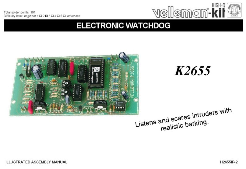
Velleman-Kit K2655 User manual

Velleman-Kit

Velleman-Kit K2655 User manual

Velleman-Kit K8090 User manual

Velleman-Kit

Velleman-Kit K8090 User manual

Velleman-Kit K8016 User manual

Velleman-Kit

Velleman-Kit K8016 User manual

Velleman-Kit K5201 User manual

Velleman-Kit

Velleman-Kit K5201 User manual

Velleman-Kit K8055 User manual

Velleman-Kit

Velleman-Kit K8055 User manual

Popular Computer Hardware manuals by other brands

Advantech ECU-P1522LPE Startup manual

Advantech

Advantech ECU-P1522LPE Startup manual

MF DIGITAL Dolphin 5700 Quick copy

MF DIGITAL

MF DIGITAL Dolphin 5700 Quick copy

Adaptec 2010S - SCSI RAID Storage Controller installation guide

Adaptec

Adaptec 2010S - SCSI RAID Storage Controller installation guide

Toshiba D660 user manual

Toshiba

Toshiba D660 user manual

Cypress CY62138EV30 Specification sheet

Cypress

Cypress CY62138EV30 Specification sheet

TRENDnet TFW-H2PC - DATA SHEETS Quick installation guide

TRENDnet

TRENDnet TFW-H2PC - DATA SHEETS Quick installation guide

Microchip Technology Multimedia Expansion Board II user guide

Microchip Technology

Microchip Technology Multimedia Expansion Board II user guide

TRENDnet TU3-H2EC user guide

TRENDnet

TRENDnet TU3-H2EC user guide

Vorsis VP8 Plus Application note

Vorsis

Vorsis VP8 Plus Application note

Scythe Big Shuriken 2 Rev B operating instructions

Scythe

Scythe Big Shuriken 2 Rev B operating instructions

Motorola CME-12D60 user manual

Motorola

Motorola CME-12D60 user manual

AQUARIUS 32K Memory quick start guide

AQUARIUS

AQUARIUS 32K Memory quick start guide

Telit Wireless Solutions BlueMod+S42 Hardware user's guide

Telit Wireless Solutions

Telit Wireless Solutions BlueMod+S42 Hardware user's guide

Sony DSBK-210 installation instructions

Sony

Sony DSBK-210 installation instructions

Cables to Go 29970 user guide

Cables to Go

Cables to Go 29970 user guide

NXP Semiconductors TWR-PXS2010 quick start guide

NXP Semiconductors

NXP Semiconductors TWR-PXS2010 quick start guide

Christie Cine-IPM Specifications

Christie

Christie Cine-IPM Specifications

rtd cpuModule CMi36786HX user manual

rtd

rtd cpuModule CMi36786HX user manual

manuals.online logo
manuals.online logoBrands
  • About & Mission
  • Contact us
  • Privacy Policy
  • Terms and Conditions

Copyright 2025 Manuals.Online. All Rights Reserved.