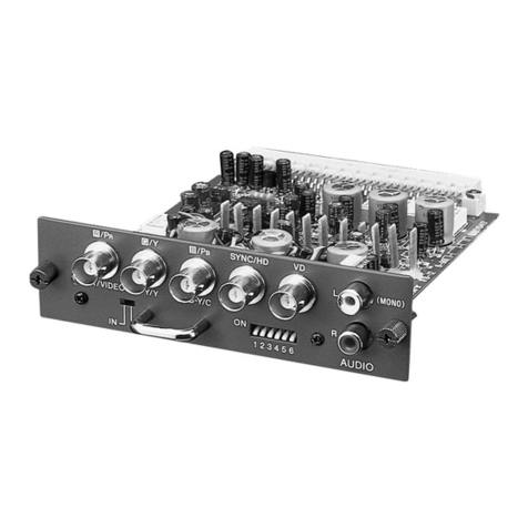
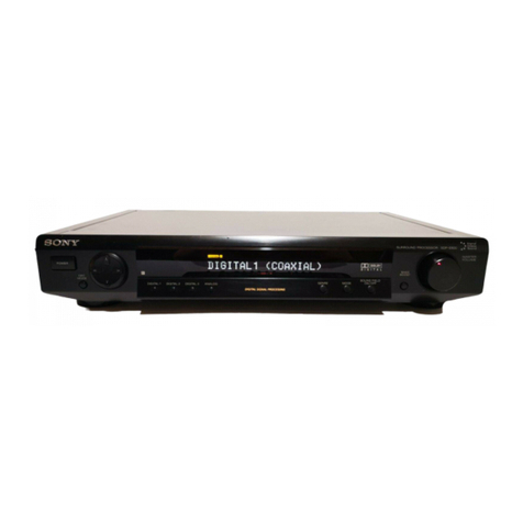
Sony DSBK-210 User manual

2
3-205-213-01(1)
2000 Sony Corporation
SDTI-CP
Output Board
設置説明書 3ページ
Installation Instructions Page 15
Manuel d’installation Page 27
Installationsanleitung Seite 39
Istruzioni per l’installazione Pagina 51
お買い上げいただきありがとうございます。
電気製品は、安全のための注意事項を守らないと、
火災や人身事故になることがあります。
•ご使用にあたっては、デジタルビデオカセットレコーダー本体
に付属の取扱説明書の「安全のために」と「 」、「 」
をよくお読みください。お読みになったあとは、いつでも見ら
れるところに必ず保管してください。
•本基板の取り付けは、必ずお買い上げ店またはソニーのサービ
ス窓口にご依頼ください。
JP
GB
FR
DE
IT
DSBK-210


3
日
本
語
目次
JP
お客様へ ................................................................................. 3
概要 ........................................................................................ 4
追加されるメニュー項目................................................................ 5
フィード再生操作 ............................................................................ 6
DSBK-210の構成品 ...................................................................... 8
取り付け ................................................................................. 9
お客様へ
9ページ以降の設置説明(「取り付け」の項)は、特約店およびソニーの
サービス窓口用の設置説明書です。
お客様がこの設置説明書に記載された作業を行うと、火災や、感電やけ
がなどの人身事故につながることがあります。
お客様自身では絶対に取り付け作業をしないでください。
本基板の取り付けは、必ずお買い上げ店またはソニーのサービス窓口に
ご依頼ください。
日本語

4
SDTI-CPアウトプットボードDSBK-210は、ソニーデジタルビデオカセットレ
コーダーDSR-2000のオプション基板です。DSR-2000に本基板を取り付け
ると、SDTI-CP1)インターフェースを装備したMPEG対応のレコーダー
(MSW-2000、MAV-555/2000など)との接続が可能になります。
本基板の出力映像信号は、MPEG24:2:2Profile@MainLevelによるI
フレームオンリー方式のエンコード出力となっています。メニュー操作で
50/40/30Mbpsのビットレートが選択できます。
◆ 本基板を装着するためにはDSR-2000のアップグレードが必要となります。
詳細は、お買い上げ店またはソニーのサービス窓口にお問い合わせくださ
い。
概要
.......................................................................................................................................................................
1) SDTI-CP(SDTIContentPackage)は、SDTI(SerialDataTransport
Interface)フォーマット(SMPTE305M)に基づいて、データストリーム多 重 方
式でMPEG-ESなどのコンテントパッケージを伝送するMPEG信号伝送
フォーマット(SMPTE326M)です。

5
追加されるメニュー項目
本基板をDSR-2000に取り付けると、セットアップメニューに以下の項目が
追加されます。
◆ メニューの操作方法については、DSR-2000の取扱説明書をご覧ください。
表の設定の欄で□で囲んである値が、工場出荷時の設定です。
項目番号
017
111
914
915
項目名
SUBSTATUS
DMC/FEEDPLAY
SDTI-CPOUTPUTBITRATE
SDTI-CPOUTPUT
FORWARD
ERRORCORRECTION
設定
モニター画面に文字情報としてスーパーインポーズ
するサブ情報を選択する。
OFF:サブ情報は出力しない。
TC MODE:内蔵タイムコードジェネレーターの動
作状態
AUDIO MIX MODE:オーディオ入力信号のミキ
シング状態
TAPE REMAIN:テープ残量
CP OUT BIT RATE:メニュー項目914で設定
したビットレート
DMCEDITボタンの機能をDMCモードとするか
フィードモードとするかを選択する。
DMC:DMC再生またはDMC編集を可能にする。
FEED:フィード再生またはオートフィード再生を可
能にする。
◆フィード再生およびオートフィード再生について
は、次 ページの「フィード再生操作」をご覧くださ
い。
MPEG2エンコード出力のビットレートを設定する。
50MbpsI-Only
40MbpsI-Only
30MbpsI-Only
SDTI-CP出力信号の伝送エラー保護のために、誤
り訂正符号(FEC:ForwardErrorCorrection)を付
加して送信するかどうかを選択する。
ON:FECを付加する。
OFF:FECを付加しない。

6
フィード再生操作
メニュー項目111をFEEDに設定すると、SDTI-CPインターフェース対応
のノンリニア編集システムやディスクレコーダーを接続して、フィード再生を
行うことが できます。
ご注意
•DSR-2000では、1倍速のみのフィード再生に対応しています。
•DSR-2000のSDTI-CP出力は、他の出力に対して3フレーム分遅れた位
相で出力されます。
フィード再生
DSR-2000に待ち受け記録が可能なレコーダー(RECEIVESTANDBY機
能を持つMAV-555/2000など)を接続して、本機でフィード再生を行うこと
により、再生信号を送出するVTR(DSR-2000)側からレコーダーの記録動
作を制御することができます。
1DMCEDITボタンを押したままPLAYボタンを押す。
両方のボタンが点灯し、フィード再生が開始します。
同時にレコーダー側で記録が開始します。
2再生を停止したい位置でSTOPボタンを押す。
再生および記録が停止します。
概要

7
オートフィード再生
DSR-2000で記録開始点(IN点)と記録終了点(OUT点)を設定してオート
フィード再生を行うと、待ち受け記録が可能なレコーダー側で、IN点から
OUT点までの区間をそのまま記録することができます。
1DSR-2000でIN点とOUT点を設定する。
2DMCEDITボタンを押したままPREVIEWボタンを押す。
DSR-2000は、IN点の5秒前(メニュー項目001で変更可能)の位置ま
でプリロールし再生を開始します。OUT点を通過後2秒間ポストロー
ル走行してから、再生を停止します。
レコーダー側では、IN点からOUT点までの区間が記録されます。

8
DSBK-210の構成品
DSBK-210は、下図の品目で構成されています。
IF-821基板
ハーネス(2連同軸
ケーブル)
コネクターパネル ネジ (M3×6、銀 色 )
外菊ワッシャー
概要

9
DSBK-210をDSR-2000に取り付ける手順は、以下の通りです。
1DSR-2000の天板を外す。
ネジ3本をゆるめて、天板ストッパーおよびブランクパネルから引き出
すようにして 外 す。
2基板押さえを外す。
ネジ1本をゆるめて、基板押さえを持ち上げ、基板押さえガイドがら引
き出 すようにして 外 す。
天板ストッパー
ネジ ブランクパネル
基板押さえ
取り付け
ネジ
ネジ
基板押さえガイド
ネジ
(続く
)

10
3ブランクパネルを外す。
ご注意
ブランクパネルとネジをなくさないように保管してください。
4ハーネスを、コネクターパネル取り付け用開口部を通してコネクターパ
ネルの2つのコネクターに接続した後、コネクターパネルをDSR-2000
にネジ止めする。
ブランクパネル
ネジ
コネクターパネル
ハーネス
付属のネジ(銀色)とワッシャー
取り付け

11
5ハーネスをIF-821基板上のDIF-109基板にあるCN200およびCN201
コネクターに接続する。(どちらのコネクターにも同じ信号が出力されま
す。)
6IF-821基板を基板スロット(外側から4番目)に差し込む。
差し込んだ基板下部の3個のコネクターとDSR-2000本体底部の3個
のコネクターを合わせて、コネクターが接続されるまで基板をしっかり
押し下げる。
CN200、CN201コネクター
DIF-109基板
IF-821基板
(続く
)

12
7ハーネスを、基板スロット脇の突起に沿わせて導き、2つのケーブルホ
ルダーと基板スロット横の切込みにはめ込んだ後、フェライトコアを
ケーブルホルダー先の窪みに収める。
フェライトコア
取り付け

13
8手順2で外した基板押さえを元どおりに取りつける。
基板押さえを基板押さえガイドに合わせて押しこんでから、ネジ穴を
合わせてネジを締める。
このとき、基板押さえ下面の6対のツメが、6個の基板スロットに 装 着
されている基板をそれぞれはさむ位置になっていることを確認する。
9DSR-2000の天板を取り付ける。
基板押さえのツメ
ネジ
基板押さえガイド


15
English
For the customers in the USA
This equipment has been tested and found to comply with the
limits for a Class A digital device, pursuant to Part 15 of the
FCC Rules. These limits are designed to provide reasonable
protection against harmful interference when the equipment is
operated in a commercial environment. This equipment
generates, uses, and can radiate radio frequency energy and, if
not installed and used in accordance with the instruction
manual, may cause harmful interference to radio
communications. Operation of this equipment in a residential
area is likely to cause harmful interference in which case the
user will be required to correct the interference at his own
expense.
You are cautioned that any changes or modifications not
expressly approved in this manual could void your authority to
operate this equipment.
The shielded interface cable recommended in this manual must
be used with this equipment in order to comply with the limits for
a digital device pursuant to Subpart B of Part 15 of FCC Rules.
This device complies with Part 15 of the FCC Rules. Operation
is subject to the following two conditions: (1) This device may
not cause harmful interference, and (2) this device must accept
any interference received, including interference that may cause
undesired operation.
For the customers in Canada
This Class A digital apparatus complies with Canadian ICES-
003.
For the customers in Europe
This product with the CE marking complies with the EMC
Directive (89/336/EEC) issued by the Commission of the
European Community.
Compliance with this directive implies conformity to the
following European standards:
• EN55103-1: Electromagnetic Interference (Emission)
• EN55103-2: Electromagnetic Susceptibility (Immunity)
This product is intended for use in the following Electromagnetic
Environment(s):
E1 (residential), E2 (commercial and light industrial), E3 (urban
outdoors) and E4 (controlled EMC environment, ex. TV studio).
GB
English

Table of Contens
16
Table of Contents
Overview......................................................................... 16
Additional Menu Items .................................................17
Feed Playback Operations ............................................18
Components of the DSBK-210.....................................20
Installation...................................................................... 21
The DSBK-210 SDTI-CP Output Board is an optional board
for the Sony DSR-2000/2000P Digital Videocassette Recorder.
Installing this board in the DSR-2000/2000P allows connection
to an MPEG-supporting recorder (such as the MSW-2000/
2000P or MAV-555/2000), equipped with an SDTI-CP1)
interface.
The video signals output by this board comply with MPEG2
4:2:2 Profile @ Main Level intra-frame only encoding. It is
possible to select the bit rate as 50, 40, or 30 Mbps by a menu
operation.
Installing this board requires an upgrade to the DSR-2000/
2000P. For details, consult your Sony service representative.
Overview
1) SDTI-CP (SDTI Content Package) is based on the SDTI (Serial Data
Transport Interface) format (SMPTE 305M), and is an MPEG signal
transport format (SMPTE 326M) for content package transfer of
MPEG-ES and so forth, using data stream multiplexing.
..........................................................................................................................

17
Additional Menu Items
When this board is installed in the DSR-2000/2000P, the
following additional items appear in the setup menus.
For details of how to use the menus, refer to the Operating
Instructions for the DSR-2000/2000P.
In the table, the settings enclosed in a box are the factory
default values.
Item number Item name Settings
017 SUB STATUS Select supplementary status information to be
displayed as superimposed text information on
the monitor screen.
OFF : No “sub” information
TC MODE: Operating status of internal time
code generator
AUDIO MIX MODE: Mixing status of audio input
signals
TAPE REMAIN: Remaining tape
CP OUT BIT RATE: Bit rate selected by menu
item 914
111 DMC/FEED PLAY Select the function of the DMC EDIT button as
DMC mode or feed mode.
DMC : Enable DMC playback or DMC editing.
FEED: Enable feed playback or auto feed
playback.
For details of feed playback and auto feed
playback, see the section “Feed Playback
Operations” on the next page.
914 SDTI-CP OUTPUT
BIT RATE Set the bit rate for MPEG2-encoded output.
50Mbps I-Only
40Mbps I-Only
30Mbps I-Only
915 SDTI-CP OUTPUT
FORWARD ERROR
CORRECTION
Select whether or not to add error correcting
codes (FEC: Forward Error Correction) to
protect against transmission errors on the SDTI-
CP output signal.
ON : Add FEC.
OFF: Do not add FEC.

18
Feed Playback Operations
When menu item 111 is set to FEED, then by connecting a
nonlinear editing system or disk recorder which supports the
SDTI-CP interface, feed playback is possible.
Notes
• The DSR-2000/2000P only supports feed playback at normal
speed.
• The SDTI-CP output of the DSR-2000/2000P has a phase
delay of 3 frames with respect to other outputs.
Feed playback
By connecting the DSR-2000/2000P to a recorder (such as the
MAV-555/2000) capable of on-demand recording (the
“RECEIVE STANDBY” function), the DSR-2000/2000P can
provide feed playback. This allows recording operations on the
recorder to be controlled from the VTR (DSR-2000/2000P)
transmitting the playback signal.
1Hold down the DMC EDIT button, and press the PLAY
button.
Both buttons light, and feed playback starts.
Recording starts simultaneously on the recorder.
2To stop playback, press the STOP button.
This stops both playback and recording.
Overview

19
Auto feed playback
By setting the recording IN point and recording OUT point on
the DSR-2000/2000P and carrying out auto feed playback, on a
recorder capable of on-demand recording the segment from the
IN point to the OUT point is recorded automatically.
1On the DSR-2000/2000P, set the IN and OUT points.
2Hold down the DMC EDIT button, and press the
PREVIEW button.
The DSR-2000/2000P prerolls to a point 5 seconds before
the IN point (this preroll time is variable with menu item
001). After 2 seconds of postroll following the OUT point,
the playback stops.
On the recorder, the segment from the IN point to the OUT
point is recorded.

20
Connector panel
IF-821 board
Screw (M3 × 6,
silver-colored)
Washer
Components of the DSBK-210
The DSBK-210 consists of the following items.
Overview
Harness (two coaxial cables)
Table of contents
Languages:
Other Sony Computer Hardware manuals

Sony
Sony BKMW-E2000 User manual

Sony
Sony PCWA-C150S - Wireless Lan Pc Card User manual

Sony
Sony HFBK-SD1 User manual

Sony
Sony PCWA-C700 - Wireless Lan Dual Pc Card User manual

Sony
Sony DSBK-1801 User manual

Sony
Sony PCWA-C100 User manual

Sony
Sony BPU4000 User manual

Sony
Sony DVBK-1000 User manual

Sony
Sony HKPF-1125A User manual

Sony
Sony ESBK-7051 User manual

Sony
Sony DVBK-2000 User manual

Sony
Sony HR-MPS User manual

Sony
Sony PDBK-201 Quick start guide

Sony
Sony HKSR-5103 User manual

Sony
Sony SDP-E800 User manual

Sony
Sony PCWA-C100 User manual

Sony
Sony HKSR-5804 User manual

Sony
Sony BKLE-103PCI User manual

Sony
Sony BPU-4500 User manual

Sony
Sony BKM-101C User manual