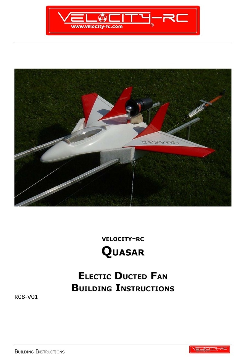
VELOCITY-RC T-33A Shooting Star Instruction Manual

VELOCITY-RC
T-33 SHOOTING STAR
ELECTIC DUCTED FAN
BUILDING INSTRUCTIONS
R08-V01
BUILDING INSTRUCTIONS

T-33 SHOOTING STAR PAGE 2 OF 17
THE ORIGINAL
The Lockhee P-80 Shooting Star was the first operational jet fighter use by
the Unite States Army Air Forces. As one of the worl 's first successful
turbojet-powere combat aircraft, it helpe usher in the "jet age" in the USAF
an other air forces worl wi e.
The T-33 is a two-seat trainer variant with a longer fuselage. It’s first flight
where on 22 March 1948, pilote by Tony LeVier. The T-33 remaine in
pro uction until 1959 an was pro uce un er license in Japan an Cana a.
The trainer was use by more than 20 ifferent countries. A total of 6,557
T-33s were built an some are still flying.
SPECIFICATIONS (T-33A)
GENERAL CHARACTERISTICS
Crew: 2 2
Length: 37 ft 9 in 11.2 m
Wingspan: 38 ft 10.5 in 11.5 m
Height: 11 ft 8 in 3.3 m
Empty weight: 8,300 lb 3’775 kg
Max takeoff weight: 15,100 lb 6’865 kg
Powerplant: 1× Allison J33-A-35
PERFORMANCE
Maximum spee : 600 mph 970 km/h
Range: 1,275 miles ferry 2’050 km
Service ceiling: 48,000 ft 14’600 m
BUILDING INSTRUCTION

T-33 SHOOTING STAR PAGE 3 OF 17
THE MODEL
The T- 33 shooting star is a 70 mm EDF class fiberglass composite mo el jet,
comes with a scale panel line fuselage, true to scale intake with factory pre
assemble ucting an light weight balsa sheete foam wings. It’s esigne to
be powere by WM400 impeller fan an Velocity EDF motor while the
performance of the mo el coul be etermine by the no. of cell application
from nice scale spee 4s setup to high spee powere 6s set up.
The look of the T -33 coul be further enhance by a pair of scale fiberglass
tip tanks which sol separately.
This in not a plane for beginners, one requires some flying experience to
han le this high spee mo el.
We strongly recommen owner to rea at the instruction before they start
buil ing the mo el.
TECHNICAL SPECIFICATIONS
Fuselage length: 43 in 1090mm
Wingspan: 33.3 in 1125mm
Wing area: 8268 in221 m2
Weight without electronics: 27 ounces 760g
Takeoff weight: ~56 ounces ~1,6kg
CONTENT OF THE KIT
- Fiber glass fuselage, finished in metallic silver.
- Intake ducting factory preinstalled.
- Laser cutted formers factory preinstalled
- Fiber glass vertical stabilizer, finished in metallic silver
- Balsa/ply horizontal stabilizer, finished ith silver covering film
- Balsa covered foam ings, finished ith silver covering film
- WM400 EDF impeller system
- Clear canopy
- All hard are is included
Optional available: Fiberglass wing tanks
BUILDING INSTRUCTION

T-33 SHOOTING STAR PAGE 4 OF 17
ITEMS NEEDED TO COMPLETE
4 ch. Computer Ra io system w/ 3 servos.
1 Electronic brushless spee controller
1 480 size brushless motor
Lipo polymer battery
5 an 30 minute epoxy
CA glue
Threa locking a hesives
Velcro
STANDARD TOOLS:
Drill or Dremel tool
Plier/cutter
Scissor
Hobby Knife
Sol ering iron
VERY IMPORTANT GENERAL RULES
Always san paper an egrease all areas where glue will be applie .
Never apply glue irect on covering film nor on painte surfaces.
Secure all screws an nuts with threa locking a hesives (e.g. Loctite
or similar).
CHECKING THE CONTENT OF THE KIT
Fiberglass fuselage
Film covere wings
Fiberglass fan access oor
Fiberglass vertical stabilizer
Film covere horizontal stab
Clear canopy
Div. har ware accessory
Decal set
BUILDING INSTRUCTION

T-33 SHOOTING STAR PAGE 5 OF 17
PREPARING THE WINGS
Mark the position for the four aileron
hinges ….
an cut the slots to insert the hinges into
wing an aileron.
Sli e in the hinges to check for correct
position an alignment. Do not glue in the
hinges at this time. Remove hinges an
ailerons again.
Mark the position for the aileron servo
pocket on the top si e of the wing. If you
plan to install lan ing gears, you may
install the servos from the bottom si e.
The outline of the pocket is epen ing of
the use servos.
Cut out carefuly the pocket for the servo.
Remove the foam completely. Take care
to the balsa cover. You will nee it later
to close the servo pocket.
BUILDING INSTRUCTION

T-33 SHOOTING STAR PAGE 6 OF 17
Drill a hole into the root rib of the wing
for the servo cable. The hole in the foam
can be one with a hot wire.
Prepare a servo bracket for the servo
which will fit into the aileron servo pocket.
A just the servo arm in the vertical
position if the servo is in its neutral
position.
The top si e of the servo case shoul be
in parallel to the top si e of the wing but
about 1mm below the surface.
BUILDING INSTRUCTION

T-33 SHOOTING STAR PAGE 7 OF 17
At the en you shoul be able to place the
balsa cover over the servo.
If all parts will fit, glue in the servo
bracket with the servo into the wing.
Route the servo wires through the root
spare. Lengthen the servo cables to
360mm measure from the root rib.
Glue the hinges first in place on the wing
si e with thin CA glue or – better- with
special hinge glue. When the glue has
cure fit the aileron an glue in the hinge
on this si e. Check for free movement of
the aileron.
Increase the outer rilling in the control
horn to 2mm an install the pushrod
connector in the control horn.
Secure the nut ith some glue so it on’t
come of hen you’re flying the plane.
Mark the location of the control horn on
the ailerons.
Drill two holes (2mm) for the screws to
fix the control horn.
Tighten the control horn by using the
plate on the bottom si e of the aileron.
BUILDING INSTRUCTION

T-33 SHOOTING STAR PAGE 8 OF 17
Prepare the pushro by tigthening up a
clevis. Sli e in the pushro into the
connector on the control horn an plug in
the clevis into the lowest possible rilling
in the servo arm (~10mm from axle)
Now you shoul have alrea y a juste
the aileron movements by using the
appen e template. A just it to 8mm up
an 6mm own. Apply about 35% expo to
the ailerons.
Repeat the same process for the secon
wing.
BUILDING INSTRUCTION

T-33 SHOOTING STAR PAGE 9 OF 17
PREPARING THE HORIZONTAL STAB
Remove the covering film on the
horizontal stab in the center section
with a hobby cutter an san the woo
surface lightly with a fine grit san
paper before epoxy is being appile on
the surface.Repeat the same process at
the bottom si e of the stab as well.
Mark the position for the four elevator
hinges ….
an cut small slots to insert the hinges
into stab an elevator.
Sli e in the hinges to check for correct
position an alignment.Take note to
apply CA to all the hinges only at the
ru er si e.
BUILDING INSTRUCTION

T-33 SHOOTING STAR PAGE 10 OF 17
PREPARING THE FUSELAGE
First assemble the WM400 Fan
accor ing the WM400 Instruction
manual
Place the WM400 fan through the fan
access oor into its position at the en
of the intake tube. Cut out the nee e
place for the motor cables or copper
stripes into the intake uct. Check for
the correct position of the fan mounts
to the flange at the en of the intake
uct. Be sure the fan housing is well
inserte into the ucting; it shoul be
slotte into the uct snugly.
In the kit, there are two semi roun e
woo formers that serving both
purposes – servo elevator mounting
an fan support.
The formers are being installe into the
fuselage by having one si e of the
formers epoxy first then follow by the
next former ue to the limite space
opening hatch esign on the fuselage
Picture shows the fully assemble
formers for WM400 Fan an elevator
servo insi e the fuselage.
Just sli e this preassemble formers
more to the front so they will act as
support for the fan. Glue in the former
to its final position.
Once epoxy is cure , rill four holes for
the screws to allow fan housing to be
mounte .
Buil a thrust tube from a thin A3 foil.
A template at the en of the manual is
provi e for making a thrust tube
mounte at the back of the wm 400.
Print out the 3 pages from this template
an tape them together. On the foil, let
an overlap of 10mm an use 3M tape to
fully seal up gap to form up a tube.
BUILDING INSTRUCTION

T-33 SHOOTING STAR PAGE 11 OF 17
Picture shows a nicely one up thrust
tube.Be sure to check if the thrust well
glue or tape properly to the fan
San paper the slot surface with a
me ium grit san paper to allow the
horizontal stab to sli e into place before
applying the surface with epoxy.
At this point, you shoul be able to
sli e in the horizontal stab without big
force. But on’t glue in the stab now.
Cut away the rear section to allow easy
access of the elevator ru er to be
glue together later on.
The next step is to mount the vertical
stab woo by inserting it through the
vertical stab slot from the fuselage
internal.
BUILDING INSTRUCTION

T-33 SHOOTING STAR PAGE 12 OF 17
Glue in the former in the vertical fin
area. It may be helpful to reinforce the
former temporarily with a horizontal
piece of ply. This allows the use of a
clamp to hol the former in place firmly
while epoxy glue is being cure .Be
sure not to over clampe the fuselage,
it may amage the fuselage. Once
epoxy is cure , remove the
reinforcement stick as shown in the
picture.
San the fuselage an wing root first.
Drill a small hole to allow servo wires to
go through.
Pre assemble the har woo wing joiner
in the fuselage an wing an see if the
wing fits nicely before applying it with
epoxy. Besure the v-shape si e of the
wing spar is place fits into the fuselage
si e nicely. Repeat same process on
other opposite wing.
Start by gluing one wing panel with 30
minute epoxy. First apply some epoxy
insi e the wing joiner slot in the
fuselage. Press the wing spar insi e the
fuselage.
Remove excess epoxy. Now apply
epoxy in the wing spar slot in the wing
root an also apply epoxy on the wing
root. Sli e the wing over the har woo
wing spar an press the wing against
the fuselage.Make sure the lea ing an
trailing e ge are both aligne to the
fuselage.Remove the excess epoxy with
a clean cloth an cleaning alcohol.
Procee with the other wing panel the
same way.
While glue is curing place fuselage an
wings on 4 battens. The battens place
at the wing tips are 10mm larger then
the battens on the fuselage / wing
joining point.
BUILDING INSTRUCTION

T-33 SHOOTING STAR PAGE 13 OF 17
Once glue is cure , glue in the
horizontal stab by using 30 min epoxy.
Apply the glue from the inner an outer
si e of the fuselage. Check for
symmetrical an horizontal position.
If the glue is cure , insert the elevator
ru er an glue in the 4 hinges
Install the elevator servo an a just the
servo arm in the 90° position if the
servo is in its neutral position.
Cut out a small slot at the back of the
fuselage as shown to allow the push ro
to go through an connect to the
elevator servo horn. The ro shoul
straight connecting from the servo to
the elevator control horn.Make sure the
ro is not ben e .
Screw up the control horn to its nee e
position.
Picture shows connecting ro being
inserte . Fine tuning a justment work
to the elelvator shoul be one when
mo el is fully assemble . There is a
template appen e for a justing the
elevator ru er to +/- 10mm.
BUILDING INSTRUCTION

T-33 SHOOTING STAR PAGE 14 OF 17
INSTALLING THE VERTICAL STAB
First san own the paint on all places
where you will have to apply the glue.
Also san the inner si e of the vertical
stab to allow the glue to bon firmly.
Glue in the vertical stab former from
balsa. Check for correct position. The
former may not cross the former from
ply.
This picture shows the position for the
vertical stab former only. Of course it’s
installe insi e the vertical stab.
Apply 30 minute epoxy glue along the
a hesion surface area.
Hol the vertical stab in place with
clamps. A just it exactly vertical an
remove excess epoxy with a clean cloth
an cleaning alcohol.
BUILDING INSTRUCTION

T-33 SHOOTING STAR PAGE 15 OF 17
CANOPY
First check the correct size an position
of the hole an the two slots in the
front canopy section of the fuselage.
Glue in the 2 plywoo flaps into the
slots from the canopy front plate while
the frontplate is fixe on it’s place on
the fuselage. Avoi gluing the frontplate
to the fuselage.
At the same time glue in also the two
magnets into frontplate an fuselage
respectively. Place a thin foil between
the two magnets. It’s very important
that the magnets will fit absolutely
exactly together.
Check also the correct size an position
of the hole in the back canopy section.
Glue in the woo en owel stick into the
hole from the canopy back plate while
the frontplate is fixe on it’s place on
the fuselage.
Now san the e ges of the canopy front
an back plate so that it fits within the
outlines of the fuselage an ABS
canopy.
The prepare front an back plates for
the cockpit.
Trim the plastic along the marke line
an check until you have a goo fit of
the ABS canopy.
Place a piece of thin plastic film over
the cocpit area.
Put the canopy front an back plate to
it’s position on the fuselage, an o
some last a justments to the canopy
plates an ABS canopy.
Now you can glue the ABS canopy in
place with 5 minute epoxy or better
with canopy glue.
While glue is curing hol ABS canopy in
place with a tape.
BUILDING INSTRUCTION

T-33 SHOOTING STAR PAGE 16 OF 17
BUNGEE HOOK
If you are starting the T-33 with a
bungee, you have to install now a
bungee hook. The position for this is
locate 55mm behin the air intake.
Before inserting the hook, glue in a
reinforcement from 3mm ply to the
bottom of the fuselage (about 20mm x
50mm).
INSTALLING THE ELECTRONICS
Now it’s time to install all the electronic
stuff into the fuselage.
Typically the receiver will be place in
the section behin the fan. This allows
short servo cables. Use velcro or
ouble-face scotch tape to hol the
receiver in place.
Best place for the ESC is the room
between Fan an cockpit. Use velcro or
ouble-face scotch tape to hol the
ESC on place.
BATTERIE TRAY AND CG
The CG (center of gravity) will be
a juste with the position of the
batterie pack. So this position is
epen ing of the use equipement.
Determine in a first step the
aproximate position for the batterie
pack. To o this, all the parts must be
installe into the T-33.
By changing the position of the batterie
pack fin the CG point which is locate
475mm behin the fuselage nose.
Once the approximate position is
known, prepare a battery tray which
allows an easy replacing of the batterie
pack.
The batterie pack must be secure well
on its place by using velcro tapes or
similar.
BUILDING INSTRUCTION

T-33 SHOOTING STAR PAGE 17 OF 17
Che k Before FIRST FLIGHT
CG 475mm from the nose
Elevator throws +/- 10mm with 35% exponential
Aileron throws +8mm / -6mm with 35% exponential
Check all ru er for correct irection of movements
Check all screws are tighten an secure
Do a range check with motor power on
Never fly if something oesn’t work properly
WARNING
Although the T-33 is a stable airplane, it is not a trainer or first EDF
airplane. This airplane is apable of very high speeds and therefore
an ause serious personal injury and property damage. We strongly
urge you to seek the help of an AMA approved instru tor if this is your
first air raft of this type. Please use ommon sense.
Fly in suitable areas for a high-speed air raft su h as an AMA
approved field.
Velo ity-r assumes no liability for the operation or performan e of
this produ t. It is the responsibility of the operator to use this produ t
in a safe and responsiblemanner.
BUILDING INSTRUCTION
Table of contents
Other VELOCITY-RC Toy manuals
Popular Toy manuals by other brands

Lionel
Lionel AT&SF owner's manual

GREAT PLANES
GREAT PLANES Super Sportster EP instruction manual

TPI
TPI Robotics unlocked user manual

Phoenix Model
Phoenix Model SBACH 46-55 instruction manual

GREAT PLANES
GREAT PLANES Giant Aeromaster ARF instruction manual

LeapFrog
LeapFrog Choppin' Fun Learning Pot instruction manual

Trenchworx
Trenchworx M8 Greyhound Assembly instructions

Horizon Hobby
Horizon Hobby Champ RTF instruction manual

Walachia
Walachia 36 manual

Model Engines
Model Engines ATOMIC MINI RACER instruction manual

Canon
Canon Virgin atlantic AIRBUS A340-600 Assembly instructions

LeapFrog
LeapFrog Electronic flash magic Parent guide & instructions