Time Synchronization with an External GPS/INS System
The sensors can synchronize their data with precision, GPS-supplied time pulses. Synchronizing to
the GPS pulse-per-second (PPS) signal provides users the ability to compute the exact firing time of
each data point.
To utilize these features the user must configure their GPS/INS device to issue a once-per-second
synchronization pulse in conjunction with a once-per-second NMEA $GPRMC sentence. No other
NMEA message will be accepted by the sensors. Other NMEA sentences might be misinterpreted.
The $GPRMC record may be configured for HHMMSS, HHMMSS.s, HHMMSS.ss, and HHMMSS.sss
formats.
For additionalinformation, please refer to the tables and diagrams in the following section
“Interface Cable Signal Description.”
• The serial data output from the GPS/INS should be connected to the sensor Interface
Box via the screw terminal labeled: “GPS RECEIVE.”
• The PPS output from the GPS/INS should be connected to the sensor Interface Box via the
screw terminal labeled: “GPS PULSE.”
• The ground signal(s) from the GPS/INS should be connected to the sensor Interface Box
via the screw terminal labeled: “GROUND.”
• Serial configuration for the NMEA message should be 9600 baud, 8N1.
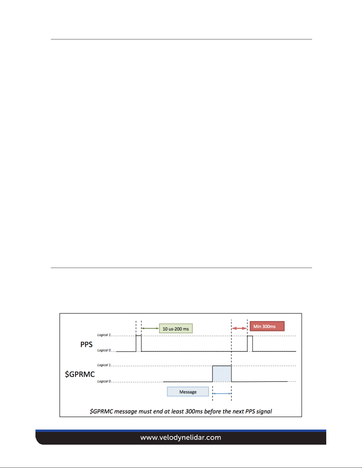
The PPS synchronization pulse and $GPRMC message may be issued concurrently or
sequentially. The PPS synchronization pulse width is not critical (typical lengths are between 10ms
and 200ms), however reception of the $GPRMC sentence must conclude no less than 300ms before
the rising edge of the next synchronization pulse.
Electrical Characteristics
• Logical “1”: Voltage must be greater than 3 V and less than 15 V.
• Logical “0”: Voltage must be less than 1.2 V
• The GPS/INS unit must be able to supply at least 2 mA of current in the logical 1 state.
• Polarity of the NMEA message is as shown in Figure 1.
Figure 1
3