VeloFox DM 06 Reference manual

第1页/共30页
DM06 Display
Functionality Introduction
Product Name:Color IPS Display
Product Model:DM 06

第2页/共30页
Firmware Modification History
Version No
Reviser
Date
Revision content
V1.01
Leo Liao
2020.12.15
Initial version
V1.02
Leo Liao
2021.03.02
1. Add declaration
2. Modify parameter contents
Hangzhou VeloFox Intelligent Technology Co,. Ltd. Ver. 1.02

第3页/共30页
Declaration
DM06 functional definition is a function definition description of the standard-version
DM06 display produced by Velofox , and is part of the technical documentation.
All of Velofox’s display products are customized according to the electric system’s
requirements. While this document is a reference for complete function definitions, operation
instructions, and error codes, any configuration difference between your display and the
standard DM06 is possible, due to various technical requirements in different ebike applications.
Please consult your drive system supplier for additional function requirements and data display.
If you have any questions about DM06 functional definition, please consult our sales or
technical support team.
Our company (VeloFox ®) reserves all the rights to interpret and explain DM06 functional
definitions.
Hangzhou Velofox Intelligent Technology Co., Ltd
Hangzhou VeloFox Intelligent Technology Co,. Ltd. Ver. 1.02

第4页/共30页
A. Product Introduction......................................................................................................................5
1. Product name and model.........................................................................................................5
2. Product introduction................................................................................................................5
3. Range of application ................................................................................................................5
4. Appearance and size ................................................................................................................5
5. Display coding rules.................................................................................................................6
B. Product manual...............................................................................................................................7
1. Specifications ..........................................................................................................................7
2. Function overview..................................................................................................................7
3. Installation ..............................................................................................................................8
4. Interface ..................................................................................................................................9
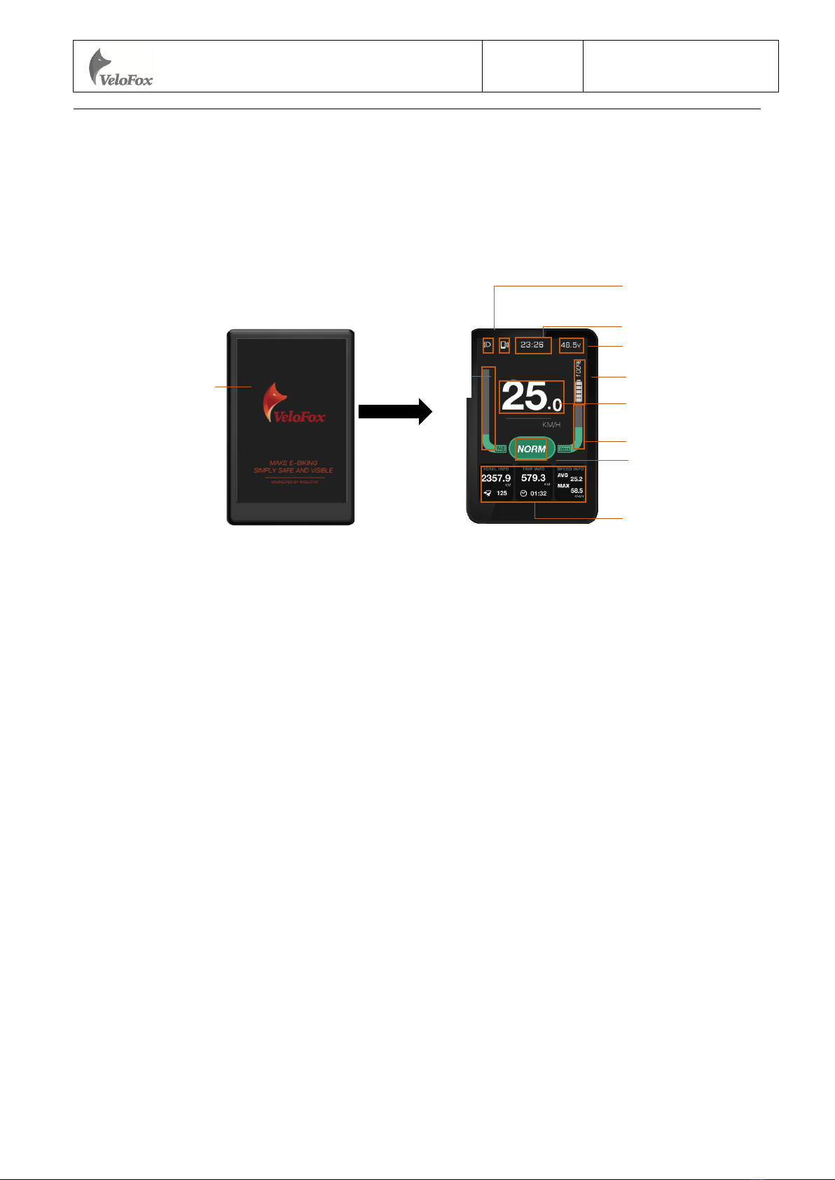
4.1 Boot interface...................................................................................................................9
4.2 Basic interface and operation...........................................................................................9
4.3 Function interface introduction......................................................................................10
Boot interface and basic function interface .........................................................................10
Other function interfaces......................................................................................................11
5. Button definition ....................................................................................................................14
5.1 Button name ...................................................................................................................14
5.2 Definition of button operation .......................................................................................15
6. Basic function operation........................................................................................................15
6.1 Turn on/off the display...................................................................................................15
6.2 Assist level switch..........................................................................................................16
6.3 Information switch .........................................................................................................16
6.4 Light control function ....................................................................................................17
6.5 Maintenance reminder ...................................................................................................17
6.6 Walk assist function .......................................................................................................18
6.7 Battery power indicator and assist power output...........................................................18
7. Setting function ......................................................................................................................20
8. Advanced setting function .....................................................................................................22
Warning................................................................................................................................22
Reference table for the circumference value corresponding to common wheel diameters .26
9. Data clearance ........................................................................................................................26
10. Error information ................................................................................................................27
11. Wire definition......................................................................................................................28
11.1 Standard wires definition: ............................................................................................28
11.2 Standard conversion wire specifications:..................................................................29
Adaptor-C2H:.......................................................................................................................29
C. Package specifications.................................................................................................................30
D. Note................................................................................................................................................30
Hangzhou VeloFox Intelligent Technology Co,. Ltd. Ver. 1.02

第5页/共30页
A. Product Introduction
1. Product name and model
IPS display of electric power assist bikes
Product model:DM06
⚫DM06 includes two versions of UART communication and CAN BUS communication
DM06_U corresponds to UART communication version;
DM06_C corresponds to CAN BUS communication version.
2. Product introduction
Tempered glass screen with 2.5D chamfered edge
3.5 inch HD high brightness full viewing angles IPS LCD display
Special screen fitting technology, great sunlight and outdoor readability
Independent operating buttons with ergonomic design
IP65 and up waterproof, excellent for outdoor use
Compatible with UART communication protocol
Service Tool function for fast firmware upgrade, parameter setting, and easy maintenance
3. Range of application
Suitable for all E-bikes that comply with EN15194 standard
4. Appearance and size
The shell material of DM06 is PC+ABS, the screen is made of imported tempered glass with 2.5D
chamfering technology. This product is suitable to be installed on the horizontal tube with a handlebar
Hangzhou VeloFox Intelligent Technology Co,. Ltd. Ver. 1.02

第6页/共30页
size ofφ22.2mm, φ25.4mm, φ31.8mm
5. Display coding rules
As shown in above picture:
Product model
Hardware version number,C-CAN, U-UART, last 2
numbers are version
Manufacture factory code,M0, M1,M2, M3
Manufacture year and week number
Production serial number
61 mm
Holder size :φ22.2mm ,φ
25.4mm,φ31.8mm
91 mm
14.5 mm
Hangzhou VeloFox Intelligent Technology Co,. Ltd. Ver. 1.02

第7页/共30页
B. Product manual
1. Specifications
①Power supply:DC 24V/36V/48V
②Rated current:42 mA
③Shutdown leakage current:<1uA
④Screen specification:3.5 inch IPS LCD display, resolution 320*480
⑤Communication method:UART/ CAN-BUS
⑥Operating temperature:-10°C ~ 60°C
⑦Storage temperature:-20°C ~ 70°C
⑧Waterproof level:IP65
2. Function overview
①Left side independent buttons with ergonomic design
②Customization of boot interface and UI
③Unit: Km/Miles, Language: English/German
④Display key riding data, speed, mileage, battery info, etc.
⑤Statistical function for power assist mode
Parameter character value(reserved)
Parameter character value (wheel size value,
700C=70, 27.5=27)
Parameter character value(speed limit information,
range from 04 to 46)
Parameter character value
(voltage,24/36/43/48/52,can be expanded)
Customer code
Customer software version number (may omit)
Hangzhou VeloFox Intelligent Technology Co,. Ltd. Ver. 1.02

⑥Walk assist function
⑦*Optional: Auto head on/off function
⑧Error code indication
⑨*Optional: Real-Time Clock for a current time indication
⑩Range and battery indication(*available if BMS provides necessary info)
○11 Percentage Analysis of total power output shared between engine and rider (*available if torque
sensor provides necessary info)
○12 Health info statistics(*available if connected to external bluetooth device)
○13 *Optional: Maintenance service reminder
○14 Parameters setting and advanced setting
3. Installation
①Display locking clip includes three handlebar sizes, size A Φ31.8mm, Φ25.4mm, and Φ22,2.
Please include the requested locking clip size in the purchase order.
Installing DM06 display: Adjust display to a position easy to operate, using M3*10 hex set to screws
and tighten. Tightening torque: 0.8N.m
*Note: Damage caused by excessive torque is not covered by the warranty.
②Place remote button on the left side of horizontal tube, using M3*10 hex set to screws and tighten.
For more remote button models, please refer to Velofox product catalogue
③Connect the 5 pin plug to the docking plug of the controller
第8页/共30页
Hangzhou VeloFox Intelligent Technology Co,. Ltd. Ver. 1.02

第9页/共30页
4. Interface
4.1 Boot interface
Boot logo interface is displayed for 3 seconds after the display is turned on. When the
communication connection is established, display enters the main interface which shows information
obtained from the controller. ( All data displayed is following communication protocol provided by
the customer)
* Animated boot interface available for customization
4.2 Basic interface and operation
①All RM series buttons are compatible with DM06 series displays
②Standard Outlet is a board end connector, which is convenient for after-sales maintenance and
replacement
Basic interface
DM06
RM01
Hangzhou VeloFox Intelligent Technology Co,. Ltd. Ver. 1.02
Power-on button
Adjust up
& down
M button

第10 页/共30页
③3.5 inch HD high brightness IPS LCD screen meets the need for customization of the boot
interface and UI interface
4.3 Function interface introduction
Boot interface and basic function interface
Boot logo interface is displayed for 3 seconds after display is turned on. When the
communication connection is established, display enters the main interface, showing real-time
information stored in the controller and battery BMS according to the communication protocol.
(Battery indicator will not show battery percentage if BMS info is not available)
Basic interface includes real-time speed info, battery info, PAS indication, real-time clock,
light-on indication, Bluetooth connection and riding data analysis.
Riding data analysis displays speed info and trip info which includes TRIP, ODO, Range, Average
speed, Max speed and trip time. Speed display value has 3 digits, maximum value is 99.9KM/H,
including one digit after the decimal point. ODO value has 4 digits, with one digit after decimal point.
After 9999.9 KM is exceeded, the decimal point is not indicated, and a 5-digit mileage value is
displayed directly, with a maximum value of 99999km. After the maximum value is exceeded, the
value is shown as the actual mileage value deducted by 100,000.
TRIP data on function interface I can be cleared by a button operation while ODO data cannot be
cleared.
Boot interface
customization available
Battery indication
Light
indication
Riding data analysis
PAS level
Boot interface
Basic interface
Real-time speed
info
Power output by motor
PAS level
side indication
RTC Real-Time clock
Battery voltage
Hangzhou VeloFox Intelligent Technology Co,. Ltd. Ver. 1.02

第11 页/共30页
Other function interfaces
Function interface I —— Battery information page
Function interface I mainly display battery info, including battery voltage, capacity, changing
cycles, and range info. Acumulated changing cycles are provided by battery BMS, if BMS does not
provide relevant information, it shows ----. Range is calculated by controller using battery BMS
capacity info, if controller can not provide range info, range info shows----.
Function interface I supports dual-battery display, that is, when the system supplied by dual-
battery, the information of each battery can be displayed on function interface I. The main battery is
marked as MAIN and the backup battery is marked as EXTENDER.
Function interface II —— Riding mode usage
Function interfaceⅡdisplays time usage analysis under each PAS level, data are calculated by the
display according to the actual riding state, shown as a percentage. To clear the time usage data under
PAS level, use button operation.
Function interface Ⅲ
Function interface Ⅲ displays power output analysis, including average power output by motor,
the maximun output by motor, and power output shared between rider and motor. Power output by
PAS 英文档位
PAS 数字档位
Hangzhou VeloFox Intelligent Technology Co,. Ltd. Ver. 1.02

第12 页/共30页
motor will follow data provided by controller, if requested info is not available from controller, display
will calculate using collected voltage and electric currents data.
* Power output shared between rider and motor requires controller’s support.
Biological analysis displays cadence info and health info, in which the cadence info needs the
support of torque sensor and other system parts, and the data source is provided by the controller.
Health info includes heart rate and calorie consumption. Heart rate info requires peripheral
Bluetooth or ANT+ equipment. calorie consumption is calculated by the controller.
* The above function interfaces Ⅲ require electric system and peripheral sensors to support
data acquisition. Without the necessary data, display will not show above information.
In the basic function interface, short press M button to switch between each function interface.
If no operation for 5s, display auto returns to basic interface.
Walk assist interface
Long press to enter walk assist mode, interface shown as below:
Maintenance reminder interface
The display can be set with regular maintenance reminders, and when reaches the set mileage
value, display will notify the user through the maintenance reminders. After the maintenance reminder
mileage is reached, display will show a notification interface every time being turned on to prompt the
Hangzhou VeloFox Intelligent Technology Co,. Ltd. Ver. 1.02

user to carry out daily vehicle maintenance. Notification interface can be cancelled by short press M
button manually. After connecting to service tool box, the maintenance reminder can be reset through
after-sales diagnostic tool, and meanwhile, the maintenance record will be registered.
Error code interface
When the display receives the error info returned by controller, it will show a detailed error code
on interface, indicating relevant electrical system fault information. The error code will be displayed
numerically in the speed display area.
第13页/共30页
Hangzhou VeloFox Intelligent Technology Co,. Ltd. Ver. 1.02

第14 页/共30页
Setting interface
Within 10s after turning on display, long press M button to enter the setting interface, short press
、 to switch between setting interfaces. Short press 、 to enter parameter picking state.
For more setting operation illustration, please refer to part 7
5.Button definition
5.1 Button name
Setting interface level 1 menu page
Hangzhou VeloFox Intelligent Technology Co,. Ltd. Ver. 1.02

第15 页/共30页
Power button: Turn on/off the display
Adjust button: Adjust the assisting power level during riding and switch functions
Long press the adjust buttons to perform specific function operation
Function button: Switch interface functions and enter into parameter setting interface
5.2 Definition of button operation
Operation
Type
Description
Short press
Press the button and soon released, while the button is released,the function
activated accordingly
Long press
Press the button and hold, when the hold time exceeds the setting time(generally
2 seconds), the function activated accordingly.
6. Basic function operation
6.1 Turn on/off the display
To turn on, long press button until boot logo interface appears and shortly enters the basic
interface. To turn off, long press button until display is turned off. If the rider does not perform
any operation on the display within set shutdown time, while speed is 0, and current is less than 1A,
then the display will be turned off automatically. Set shutdown time is self-defined by user.
on button
Hangzhou VeloFox Intelligent Technology Co,. Ltd. Ver. 1.02
Adjust
button
Power-
Function button

第16 页/共30页
6.2 Assist level switch
During normal working state,short press 、buttons to switch assist level, and change assist
mode
Power assist display modes as shown below:
Digital gear: 0-5 levels
Short press 、button to switch assist level. Switching level is not cycled, that is, after reaching 5th
level, short press button to return to off level. It’s the same when adjusting up.
6.3 Information switch
In a power-on state, short press M button to switch alternately from basic interface, function
interfaces. In a normal riding state, if the bike speed is greater than 0, and the display is not in the basic
interface, then basic interface will be automatically returned to after 5 s no operation on the M button.
The switching process of each interface, as shown below:
Hangzhou VeloFox Intelligent Technology Co,. Ltd. Ver. 1.02

第17 页/共30页
6.4 Light control function
Display supports automatic lights-on/off function, when loaded with battery and is turned on, the
default is to automatically turn on/off lights, that is the display automatically detects the ambient light
intensity and controls the turning on/off of the lights. The icon on the top right corner of the
basic interface indicates automatic lights-on state.
When automatic lights-on/off function fails, long press button to manually turn on the front
light, a light icon on top left corner of screen will appear indicating light-on status. Long press
button to manually turn the lights off.
Automatic lights-on/off function is disabled , after manually turn off the headlight. Re-start display
to enable automatic lights-on/off function.
When headlights are on, screen brightness will be lowered to preset brightness level.
6.5 Maintenance reminder
Display supports maintenance reminder function, when this function is enabled, the display will
remind the user to give ebike a maintenance check once the total mileage reached a preset value.
maintenance reminder function can be turned on/off in the setting interface and is turned on by
default. The factory default reminding mileage is 5000km which is not modifiable by users, that is,
display will remind the user to give a maintenance check once the total mileage reached 5000km.
Basic interface
Function interfaces
Hangzhou VeloFox Intelligent Technology Co,. Ltd. Ver. 1.02

第18 页/共30页
6.6 Walk assist function
When speed is 0, long press button to enter walk assist mode, motor outputs power
according to the set speed and control the actual walk speed, display shows the walk assist icon
and the real-time speed. Release button or any other button to exit walk assist mode, the motor
is turned off, and the display gets back to the basic interface. Walk assist interface, shown as below:
6.7 Battery power indicator and assist power output
Battery power information is divided into battery bar indication and remaining percentage
indication. When battery power is normal, battery capacity is divided into 5 bars. Before
communication is established, the battery percentage is not displayed, and the power bar is full and
blinks at 2Hz. After battery info is acquired, power bar will stop blinking, and displays the power
percentage. If communication is not successful within 3s, it will stop blinking and no power percentage
will be displayed.
Hangzhou VeloFox Intelligent Technology Co,. Ltd. Ver. 1.02

第19 页/共30页
After battery capacity is lower than 5% or the voltage is lower than low voltage value, display
will enter the low-voltage mode. In this mode battery level showed level 0 and border blink at 1Hz,
with no power output from the motor, and disabled assist level switch. Power assist level is displayed
as OFF or 0.
To get out of low-voltage mode, reset, and increase the voltage above low-voltage value and
battery capacity above 5%.
Percentage of battery power and power level table
(Battery % info is required from BMS or controller):
SOC
Battery level
Description
80% ≤SOC
Full battery level 5
60% ≤SOC < 80%
Level 4
40% ≤SOC < 60%
Level 3
20% ≤SOC < 40%
Level 2
10% ≤SOC < 20%
Level 1
5% ≤SOC < 10%
Level 0
0% ≤SOC < 5%
Level 0 and icon blink at 1Hz
⚫Remarks about battery indicator:
When there is a battery communication error:
1. Display will estimate the power according to the voltage and show the battery level
accordingly;
2. No battery percentage information will be shown;
3. Range information will not be displayed;
4. If the voltage is lower than the low-voltage value, the effect of the current on voltage needs to be
considered when converting to a voltage at 0 current
Hangzhou VeloFox Intelligent Technology Co,. Ltd. Ver. 1.02

第20 页/共30页
7. Setting function
Display provides specific parameter setting functions. The optional items of setting function will
be deleted according to different market and product standards. The following is the complete
parameter setting, information reading function description under the default state of display. Please
contact our sales and technical support team for confirmation in case of any discrepancies.
Within 10s after turning on display, long press M button to enter setting interface, short press 、
button to switch between setting interfaces. In any setting interfaces, short press M button to enter
parameter editing state, the blue mark indicates chosen parameter, and selected option or value will be
indicated by a white font with a grey background. Short press 、 button to edit parameters. Long
press M button to confirm parameter selection. Long press M button again to exit and return to previous
page
Selected option or value will be indicated by a white font with grey background,as shown below:
In any setting interfaces, short press M button to enter the next level menu, and long press M
button to return to the previous level menu.
First level parameter setting interface, and the description of each parameter interface is as follow:
Setting
items
Interface
Description
Setting data
Remark
Unit
setting
UNIT
Value=KM/H
MPH
Default
Value=KM/H
KM/H—
Metric
MPH—
Hangzhou VeloFox Intelligent Technology Co,. Ltd. Ver. 1.02
Table of contents
Popular Fitness Equipment manuals by other brands

Sissel
Sissel Hang UP PRO Instructions for use

SPORTSTECH
SPORTSTECH DESKFIT DF300 user manual

GE HEALTHCARE
GE HEALTHCARE MAC 2000 Operator's manual

Precor
Precor Discovery Series Assembly guide

Ironman Fitness
Ironman Fitness Gravity 4000 owner's manual

Precor
Precor Discovery Plate Loaded Line Assembly guide

BRONZE GYM
BRONZE GYM H Series Use manual

ParaBody
ParaBody GS2 user guide

Taurus
Taurus TF-B800 Assembly and operating instructions

PROZIS
PROZIS TITAN Chest Expander user manual

Xtreme Power
Xtreme Power 96137 Owner's manual and safety instructions

First Degree Fitness
First Degree Fitness E-520 Fluid Rower owner's manual