manuals.online logo
Brands
  1. Home
  2. •
  3. Brands
  4. •
  5. velorian
  6. •
  7. Lock
  8. •
  9. velorian E-BIKE BLINKERSET User manual

velorian E-BIKE BLINKERSET User manual

© velorian GmbH, Storkower Str. 115A, 10407 Berlin, Germany
https://velorian.de/ - email: suppor[email protected] - fon +49 (0) 30 3643 1679 Version DE. 01.2021.05.11
Note: When shortening the cables, it is better to
leave one or two centimetres too much cable
than too little. Be sure to turn the handlebars to
one side and run the cable along the other side
to determine the length. Experience has shown
that people tend to forget to turn in the
handlebars and a cable is quickly too short. In
this case, nothing is lost, the cable can be
reordered and replaced.
E-BIKE BLINKERSET
&
BLINKERBOX ALPHA21
Installation
Videos on assembly are available at https://velorian.de/de/ebike-blinker.php. A step-by-step instruction is described below.
General Safety Instructions
The velorian e-bike blinkerset contains small parts that can be swallowed by small children. There is a risk of injury when handling the
cables and tools. We recommend assembly in a specialist workshop. When unpacking and assembling, please make sure to keep the
small parts and tools out of the reach of small children.
The electronics in the indicator box are reverse polarity protected. This means that reversing the connection cables (mixing up plus and
minus) on turn signals, switches or the power supply will not destroy the electronics or the connected components.
However, if the connections are interchanged, e.g. the power supply is connected to the cables for the turn indicator, the electronics
will be destroyed when the current is switched on. Likewise, poor insulation of the connecting cables can cause short circuits that
destroy the electronics.
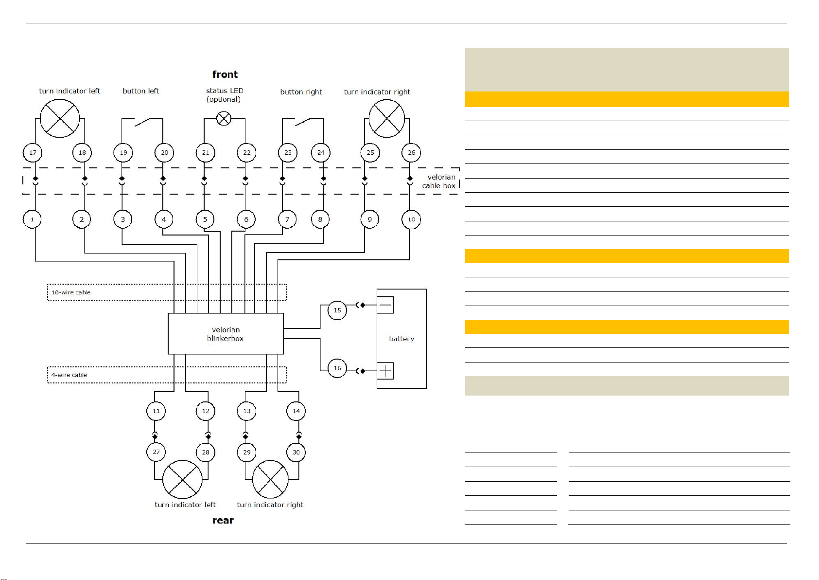
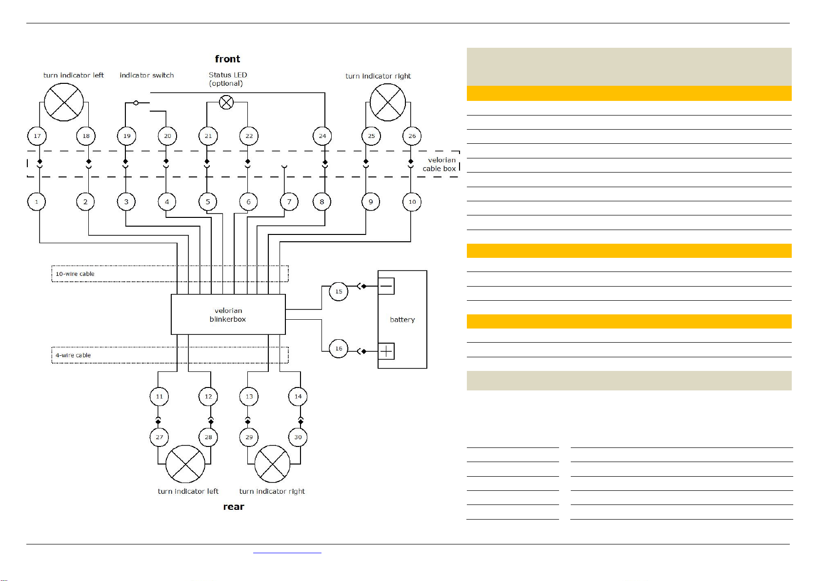
Blinkerbox
The first decision is where to mount the indicator box on the bicycle. There, it should first be attached provisionally so that the cable
lengths can be determined.
Cable Box
The next step is to mount the cable box on the handlebar stem with the longer cable ties. These are pulled through the outer tabs. The
shorter cable ties can also be pulled through the inner tabs before mounting. After connecting all the cables, they serve to secure the
cables in the cable box and thus as strain relief.
Switch and indicator in front
From the blinkerbox, the 10-wire cable should first be pulled to the handlebar.
If the velorian cable box is used, the middle of the cable box is the end point. At
this point, the cable can be shortened with a side cutter.
The cable, now shortened to length, can now be stripped, the individual strands
stripped and fitted with flat connector sleeves. We recommend the use of
appropriate tools for stripping and crimping.
Now mount the front indicators and switches, shorten the connecting cables to
the right length, strip the cable ends and fit flat plugs.
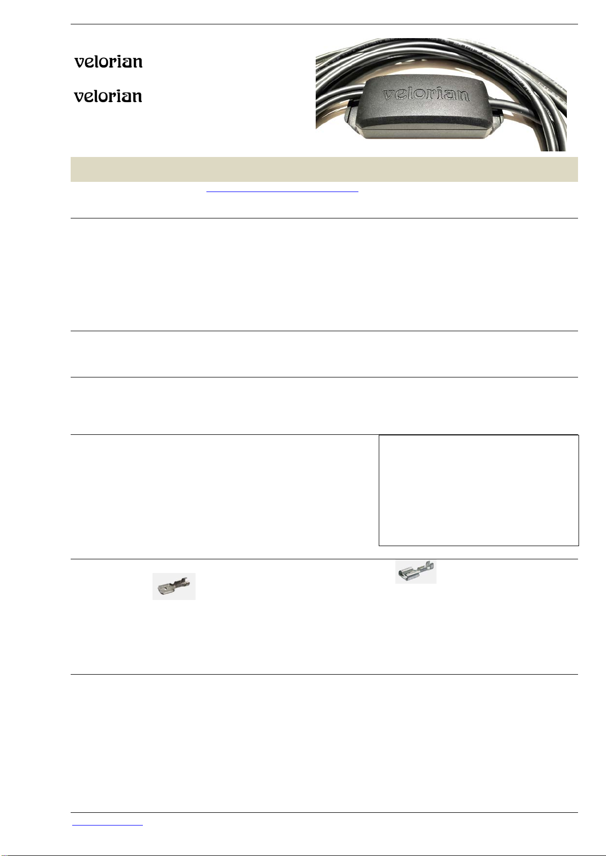
Crimping the plug connections
We recommend that you fit the cables to the indicator box with the flat plug sleeves and the indicators and switches
with the flat plugs.
As the cable cross-section of the single strands of 0.14 mm2 or 0.25 mm2 is considerably thinner than the cables with a cross-section of
0.75 mm2 usually used on bicycles, the use of special small flat connector sleeves is recommended. These are enclosed with the
blinkerset in addition to the usual crimp contacts. After crimping, insulate the flat plug sleeves and flat plugs with the enclosed heat
shrink tubing.
Connection of the power supply and first function test
Once the front turn signals and switches are connected to the indicator box, a first function test can be carried out. To do this, the 2-
wire cable of the blinkerbox is connected directly to the e-bike battery or another source such as the connecting cable of the headlight.
Alternatively, the test can be done with the help of a 12 volt power supply unit. For the connection, flat plug distributors are enclosed
with the indicator set, with which the current-supplying cable can be divided. These flat plug distributors are plugged onto flat plugs, so
flat plugs must be crimped onto the cable ends on both sides. After switching on, the front turn signals will now still flash very quickly.
This is correct because the rear turn indicators are still missing.
If a function test carried out at this point is successful, the connection to the power supply should first be disconnected again to
avoid short circuits during further assembly!
Finally, the cable box can be closed.
© velorian GmbH, Storkower Str. 115A, 10407 Berlin, Germany
https://velorian.de/ - email: suppor[email protected] - fon +49 (0) 30 3643 1679 Version DE. 01.2021.05.11
Rear indicator
First, the indicator bracket for the rear turn signals should be mounted on the bike and the turn signals mounted on the bracket. Now
the 4-wire cable can be routed to the mounting position of the rear turn signals, shortened to the correct length, the cable ends
stripped and fitted with flat plug sleeves. Similarly, the connecting cables of the turn signals are shortened to the correct length and the
cable ends are stripped and fitted with flat plugs.
Once the rear turn signals are connected, the connection to the power supply can be re-established and a final function test carried
out.
Mounting finish
At the end of assembly, the position of the switches and indicators should be checked and all screw connections tightened. The
remains of the cables and the cable ties can be disposed of in the residual waste.
Function and operating instructions
The function complies with the requirements of the StVZO (Germany) and UN ECE 50.
Operation with indicator switch (toggle switch)
When the toggle switch is mounted on an appropriately configured blinkerbox triggers flipping the toggle switch to the left the turn
signals to flash on the left side. When the switch is returned to its original position the flashing stops.
Flipping the toggle switch to the right causes the indicators on the right to flash.
If the switch is not returned to the home position, the flashing stops automatically after 2 minutes. Returning the toggle switch to its
original position and switching it on again will restart the flashing.
Triggering the hazard warning lights is not possible with the toggle switch.
Operation with buttons
When the push-buttons are mounted on an appropriately configured blinkerbox triggers a short press on the left push-button flashing
of the turn signals on the left side. If the left button is pressed again, the left turn signals stop flashing. Pressing the button on the right
side causes the indicators on the right side to flash. If the right button is pressed again, the flashing stops. Switching the flashing from
e.g. left to right can be achieved by pressing the other button in each case.
If the indicators are not switched off manually, the flashing stops automatically after 2 minutes.
The hazard warning lights are triggered by switching on the other side. Pressing and holding one button and pressing the other button
starts the warning flashing. It can be stopped again by pressing one of the buttons.
The warning flashing stops automatically after 30 minutes.
Warning function in case of failure of one of the turn signals (only with configuration for 4 turn signals)
If, for example, one of the rear turn signals fails:
- The front indicator flashes twice as fast. If the front indicator fails, the rear indicator flashes twice as fast.
- The separate status LED (if installed) flashes twice as fast.
- The sound generator in the flasher unit (if active) ticks twice as fast.
Configuration of the Blinkerbox
The indicator box can be configured for different operating modes. The push-buttons or a corresponding device and a connection to
the power supply are necessary for configuration.
The configuration is started by holding down one indicator button and pressing the other button eight times, then releasing both
buttons. After 2 seconds, the indicator is in configuration mode and the software version can be set by pressing three more buttons.
The following is an overview of which button presses determine which setting:
1st button press: number of installed turn signals: left button = 2 turn signals, right button = 4 turn signals.
2nd keystroke: button or switch operation, left button = push button, right button = switch
3rd button press: indicator sound on or off, left button = indicator sound off, right button = sound on
This results in the following key combinations to select the software versions in configuration mode:
L designates the left button, R the right button:
2 indicators switch with sound
LRR
4 indicators switch with sound
RRR
2 indicators button with sound
LLR
4 indicators button with sound
RLR
2 indicators switch without sound
LRL
4 indicators switch without sound
RRL
2 indicators button without sound
LLL
4 indicators button without sound
RLL
After entering the key combination, the configuration is completed.
The configuration is retained even after disconnection from the power supply.
Subject to technical changes.
© velorian GmbH, Storkower Str. 115A, 10407 Berlin, Germany e-line Blinkerbox alpha21
© velorian GmbH, Storkower Str. 115A, 10407 Berlin, Germany, https://velorian.de/ Version DE. 01.2021.05.11
Pin assignment for push button operation
10-wire cable of the blinkerbox
1 blue 17 Indicator front left + (yellow)
2
red
18
Indicator front left - (black)
3 green 19 Button left front (+ / - )
4 yello 20 Button left front (+ / - )
5 white 21 LED -
6 brown 22 LED +
7 grey 23 Button right front (+ / - )
8 pink 24 Button right front (+ / - )
9
black
25
Indicator front right + (yellow)
10 violet 26 Indicator front right - (black)
4-wire cable of the blinkerbox
11 yellow 27 Indicator rear left + (yellow)
12 green 28 Indicator rear left- (black)
13 brown 29 Indicator rear right + (gelb)
14 white 30 Indicator rear right - (black)
2-wire cable of the blinkerbox
15 brown Power supply – (black)
16 white Power supply + (black/white)
Technical Data Blinkerbox alpha21 (Art.-Nr: 1010101310)
EMC approval
EN 55016-2-1; 2014-12
EN 55016-2-2; 2011-09
CISPR12 ,
ISO 11451-1; 2015,
ISO 11451-2; 2015,
EN 15194
Operating voltage 6-55 Volt
Output 6 Watt
Operating temperature -20 up to +85 °C
Flashing frequency 90 pulses ± 30 pulses per minute
Protection class IP 67
© velorian GmbH, Storkower Str. 115A, 10407 Berlin, Germany e-line Blinkerbox alpha21
© velorian GmbH, Storkower Str. 115A, 10407 Berlin, Germany, https://velorian.de/ Version DE. 01.2021.05.11
Pin assignment for switch operation
10-wire cable of the blinkerbox
1 blue 17 Indicator front left + (yellow)
2
red
18
Indicator front left - (black)
3 green 19 Switch Ground (black)
4 yello 20 Switch left (red)
5 white 21 LED -
6 brown 22 LED +
7 grey 23 unoccupied
8 pink 24 Switch right (yellow)
9 black 25 Indicator front right + (yellow)
10 violet 26 Indicator front right - (black)
4-wire cable of the blinkerbox
11
yellow
27
Indicator rear left + (yellow)
12 green 28 Indicator rear left- (black)
13 brown 29 Indicator rear right + (gelb)
14 white 30 Indicator rear right - (black)
2-wire cable of the blinkerbox
15 brown Power supply – (black)
16 white Power supply + (black/white)
Technical Data Blinkerbox alpha21 (Art.-Nr: 1010101310)
EMC approval
EN 55016-2-1; 2014-12
EN 55016-2-2; 2011-09
CISPR12 ,
ISO 11451-1; 2015,
ISO 11451-2; 2015,
EN 15194
Operating voltage 6-55 Volt
Output 6 Watt
Operating temperature -20 up to +85 °C
Flashing frequency 90 pulses ± 30 pulses per minute
Protection class IP 67

This manual suits for next models

3

Popular Lock manuals by other brands

Rousseau L3 Assembly guide

Rousseau

Rousseau L3 Assembly guide

Hornbill SB-122 Troubleshooting

Hornbill

Hornbill SB-122 Troubleshooting

Schlage BE499WB user manual

Schlage

Schlage BE499WB user manual

Dormakaba La Gard Reset Box user guide

Dormakaba

Dormakaba La Gard Reset Box user guide

Alarm Lock Trilogy DK3000 Series brochure

Alarm Lock

Alarm Lock Trilogy DK3000 Series brochure

AMSEC ESL15 operating instructions

AMSEC

AMSEC ESL15 operating instructions

Ideal Security Decibel SL1000 instructions

Ideal Security

Ideal Security Decibel SL1000 instructions

Orbis ORTSA30LOKA user manual

Orbis

Orbis ORTSA30LOKA user manual

TSA TRAVEL SENTRY TSA-306 quick start guide

TSA

TSA TRAVEL SENTRY TSA-306 quick start guide

FingerTec H2i user guide

FingerTec

FingerTec H2i user guide

PNI SMART LOCK user manual

PNI

PNI SMART LOCK user manual

Amazon B07T5MMHXS quick start guide

Amazon

Amazon B07T5MMHXS quick start guide

Alarm Lock Trilogy PDL3500 datasheet

Alarm Lock

Alarm Lock Trilogy PDL3500 datasheet

Command access MLB51 installation instructions

Command access

Command access MLB51 installation instructions

Alarm Lock TRILOGY DL2700 Programming instructions

Alarm Lock

Alarm Lock TRILOGY DL2700 Programming instructions

Phoenix SELO-A operating instructions

Phoenix

Phoenix SELO-A operating instructions

Sargent IN220 installation instructions

Sargent

Sargent IN220 installation instructions

Itouchless Bio-Matic BM001 user manual

Itouchless

Itouchless Bio-Matic BM001 user manual

manuals.online logo
manuals.online logoBrands
  • About & Mission
  • Contact us
  • Privacy Policy
  • Terms and Conditions

Copyright 2025 Manuals.Online. All Rights Reserved.