Vemer S.p.A.
I - 32032 Feltre (BL) • Via Camp Lonc, 16
Tel +39 0439 80638 • Fax +39 0439 80619
e-mail: info@vemer.it - web site: www.vemer.it
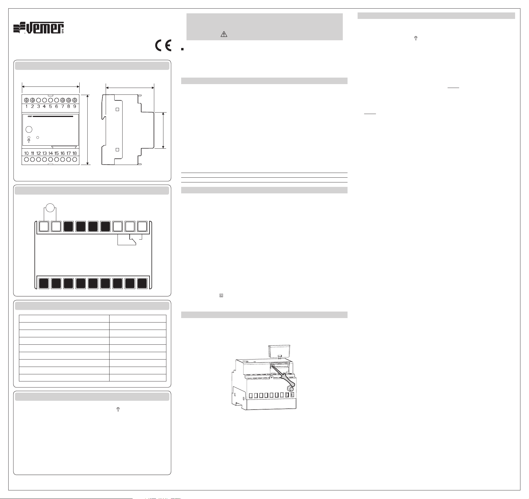
DIMENSIONS
CONNECTION DIAGRAMS
DEFAULT SETTING
DEVICE STATUS
Mod. TRILLO
TRILLO-B
V3IS00501-013
72 6
45
87
0
Out
ON
SET
TR ILLO
127 8 9
Power supply
OUT
8 A / 250 V ~
:
User manual
GSM COMMUNICATION INTERFACE
Read all instructions carefully
TrilloTrillo-B
SAFETY WARNINGS
During the installation and operation of the device observe the following instructions:
1) The device must be installed by a qualifi ed person
2) The device is aimed to be used in household premises and similar environments
3) Do not use the device for purposes other than indicated
4) The device must be installed in a electric closed panel well protected.
5) A two-pole disconnect device shall be provided as part of the building installation
6) A protection device against over-currents should be installed in the electrical system,
upstream of the device
7) When installing the device, carefully respect the wiring diagrams
8) Disconnect the device from the power supply before accessing to the terminals
9) Do not power or connect the instrument if any part of it is damaged
10) The use of a GSM device can cause interference with the functioning of electronic devices
non-screened from radiofrequency signals (electromedical devices, pacemakers, hearing
aids etc.)
11) In case of fault, do not service the device yourself but contact the after-sales service.
12) The device is aimed for use in place with over-voltage category III and pollution degree 2,
as per standards EN 61010-1.
Code Model Description
VE245700
VE293700
TECHNICAL CHARACTERISTICS
INSTALLATION
with the pin code and the answerphone deactivated
Attention. Ensure that the power cables are disconnected before inserting/remove
the sim card.
Note. If the device will be installed into a screened panel, it is possible to replace
the antenna included in the kit with an another one with 3 meters cable.
The longer antenna is available as optional. Ensure that the power cables are
disconnected before replace the antenna.
OPERATION
TURN ON/OFF INSTRUMENT (only Trillo-B)
RESET THE DEVICE
Trillo
Trillo-B
SET THE CERTIFIED NUMBERS
Setting the admin number
:
ADMIN [
Nota. If you lose the admin number, it can only be changed by forcing an
instrument reset. To retrieve automatically all the user numbers, see the
section “Sim management”.
Setting the user number (for admin only)
USERADD
USERDEL
Sim card managment (for admin only)
STORE
RESTORE
COMMANDS
Sms syntax
Password can be omitted if the command is imparted from a certified number
(admin or user).
Some commands can be give from the admin number only
.
:
Key function