Vemm Tec PTZ-BOX 3.0 User manual

IOM_Manual_EN_PTZ-BOX 3-0_097-102-003_2017 02.docx
GAS-VOLUME CONVERSION DEVICE
PTZ-BOX 3.0
Manual
Specifications
Technical Description
Mounting instructions
Configuration
Single-channel gas conversion device
Approved for installation in potentially explosive atmospheres.
February 2017

IOM_Manual_EN_PTZ-BOX 3-0_097-102-003_2017 02.docx
Safety Measures
This measurement device can be operated only by an operator trained in
compliance with the technical terms, safety regulations, and standards. It is
necessary to consider any other legal and safety regulations stipulated for special
applications. Similar measures also apply for special applications. Similar measures
also apply for using the accessories. The operator training must be in compliance
with Decree no. 50.1978 Coll.
The information in this manual does not have the power of a legal obligation from the
manufacturer’s side. The manufacturer reserves the right to implement changes. Any
changes in the manual or in the product itself can be performed at any time without any
previous alert, with the goal of improving the device or fixing any typographical or technical
mistakes.

IOM_Manual_EN_PTZ-BOX 3-0_097-102-003_2017 02.docx
TABLE OF CONTENTS
1Introduction ............................................................................................. 3
1.1 Basic device description....................................................................................... 3
1.2 Function principle................................................................................................ 4
1.3 Device dimensions............................................................................................... 8
2Device technical description ..................................................................... 8
2.1 Device architecture.............................................................................................. 8
2.2 Power supply....................................................................................................... 9
2.3 Security seals......................................................................................................12
2.4 Product label ......................................................................................................13
3Safety instructions...................................................................................14
3.1 General ..............................................................................................................14
3.2 Use in potentially explosive atmosphere.............................................................14
3.3 Risks of use.........................................................................................................14
3.4 Special conditions of use.....................................................................................15
3.5 Using different groups of gas ..............................................................................15
4Metrological characteristics ....................................................................16
4.1 Temperature measurement ................................................................................16
4.2 Pressure measurement.......................................................................................16
4.3 Compressibility calculation .................................................................................17
4.4 Volume measurement and calculation ................................................................18
5Inputs and outputs ..................................................................................20
5.1 Inputs.................................................................................................................20
5.2 Outputs ..............................................................................................................22
6Communication with the PTZ-BOX 3.0.....................................................24
6.1 RS-232 and RS-485 interfaces..............................................................................24
6.2 Optical interface IEC-1107...................................................................................26
7Functions.................................................................................................27
7.1 Parameter indication ..........................................................................................27
7.2 Actual values ......................................................................................................27
7.3 Archives .............................................................................................................28
7.4 Device configuration...........................................................................................31
7.5 Other device functions........................................................................................31
7.6 Securing the device against a change of metrological values ...............................32

IOM_Manual_EN_PTZ-BOX 3-0_097-102-003_2017 02.docx
7.7 Access passwords ...............................................................................................33
8Starting the device ..................................................................................37
9Operation................................................................................................38
9.1 Keypad ...............................................................................................................38
9.2 Menu system......................................................................................................39
9.3 Initial display ......................................................................................................39
9.4 Menu structure ..................................................................................................40
9.5 Quick Access Buttons..........................................................................................49
9.6 Change settings via the keypad ...........................................................................49
10 Mounting instructions .............................................................................51
10.1 Mechanical mounting of the device ....................................................................51
10.2 Cable connection, grounding...............................................................................54
11 Accessories (options)...............................................................................56
11.1 Assembly accessories..........................................................................................56
11.2 Intrinsically safe power supply............................................................................56
11.3 Barrier and communication modules ..................................................................56
11.4 GPRS communicators..........................................................................................56
11.5 Other accessories ...............................................................................................56
12 Specifications ..........................................................................................57
13 Intrinsically safe parameters ...................................................................62
14 Configuration ..........................................................................................64
14.1 Checking after installation ..................................................................................64
14.2 Connecting the PTZ-BOX 3.0 with a PC ................................................................64
14.3 Configuration with the GASCcomm software ......................................................65
14.4 Password in the device .......................................................................................76
15 Configuration examples...........................................................................78
15.1 Parameters display modes..................................................................................78
15.2 Setting the gas meter impulse factor...................................................................78
15.3 Pulse outputs setting ..........................................................................................81
15.4 Analogue output setting .....................................................................................86
15.5 Limits of measured values ..................................................................................89
15.6 Monitoring the external power supply................................................................91
15.7 Setting of communication with MODBUS protocol ..............................................93
15.8 Configuration of Quick Access buttons................................................................96

IOM_Manual_EN_PTZ-BOX 3-0_097-102-003_2017 02.docx
16 Exchange of pressure and temperature sensors ....................................100
16.1 Pressure and temperature sensor replacement procedure in the PTZ-BOX 3.0...100
16.2 Software settings for a new temperature sensor...............................................101
16.3 Software settings for a new pressure sensor .....................................................103
17 Additional external digital temperature or pressure sensor...................104
17.1Fitting an additional digital pressure or temperature sensor .............................104
17.2 Configuring the digital sensor in the parameter file ...........................................106
17.3 Final verification after replacement of a sensor or adding a digital sensor .........107
18 What if something does not work .........................................................109
19 Literature ..............................................................................................111
20 Documentation .....................................................................................111
21 Software................................................................................................112
22 Used trade marks ..................................................................................112
23 List of figures.........................................................................................113
24 List of Tables .........................................................................................114

PTZ-BOX 3.0
1
Used symbols and definitions
Symbol
Description
Unit
AGA8-G1
Compressibility calculation method
AGA8-G2
Compressibility calculation method
AGA8-92DC
Compressibility calculation method
AGA NX-19 mod
Compressibility calculation method
ASC
Accredited Service Centre
BTS
Base Transceiver Station
CL-1 Module
Analogue output module (4-20mA)
CRC
Checksum –used for data protection
CTR
Communication protocol
Kx MODULE
Some of the products of series Kx module (K1
MODULE, K2 MODULE, K3 MODULE, K3/A MODULE,
K4 MODULE, K4/A MODULE)
DLMS
Communication protocol
DC
Direct Current voltage
dE
Increment of energy
MJ
dV
Increment of primary volume Vmor Vc
m3
dVb
Increment of base volume
m3
dVc
Increment of corrected primary volume
m3
dVm
Increment of primary volume
m3
E
Energy
MJ
Es
Estimated value of energy
MJ
PA1.1
Digital pressure sensor PA1.1 (RS485/Modbus
connection)
TA1.1
Digital temperature sensor TA1.1 (RS485/Modbus
connection)
EMC
Electromagnetic compatibility and resistance
EMI
Electromagnetic radiation
firmware, FW
Software equipment loaded in the device
GOST NX-19
Compressibility calculation method ( related with
AGA NX-19 mod) according to VNIMS directive (valid at
temperature range -23°C to +60°C)
Hs
Combustion heat (Superior heating value)
MJ/m3
IS
intrinsic safety, intrinsically safe
JBZ-0x
Some of the JBZ-01, JBZ-02, JBZ-02/A products
Modbus
Communication protocol designed by Modicon [15]
M900
Specific communication protocol
SGERG-88
Calculation method of gas compressibility factor, more
details in [17]
SNAM
Communication protocol
SW
Software for PC
C
Conversion factor
-
K
Ratio of compressibility factors (Z/Zb)
-
kp
Gas meter constant (number of impulses per 1 m3)
imp/m3

PTZ-BOX 3.0
2
Symbol
Description
Unit
N
Number of input impulses from gas meter
imp
p
Absolute pressure at measurement conditions
kPa
pb
Absolute pressure at base conditions
kPa
Qm
Flowrate at measurement conditions (further primary
flowrate)
m3/h
Qb
Flowrate at base conditions
m3/h
T
Absolute temperature at measurement conditions (T = t +
273.15)
K
t
Gas temperature
°C
Tb
Absolute temperature at base conditions
K
V
Volume Vmor Vc
Vm
Volume at measurement conditions (further primary
volume)
m3
Vc
Corrected volume at measurement conditions (volume
corrected based on correction curve of gas meter)
m3
Vb
Volume at base conditions (hereinafter also the
standardized volume)
m3
Vbs
Error volume at base conditions (hereinafter also the
error standardized volume)
m3
Vs
Error volume at measurement conditions (hereinafter
also the error operational volume)
m3
Vd
Difference of primary volume
m3
Vbd
Difference of base volume
m3
Vf
Tariff counter of primary volume
Vbf
Tariff counter of base volume
Z
Compressibility factor at measurement conditions
Zb
Compressibility factor at base conditions

PTZ-BOX 3.0
3
1 Introduction
1.1 Basic device description
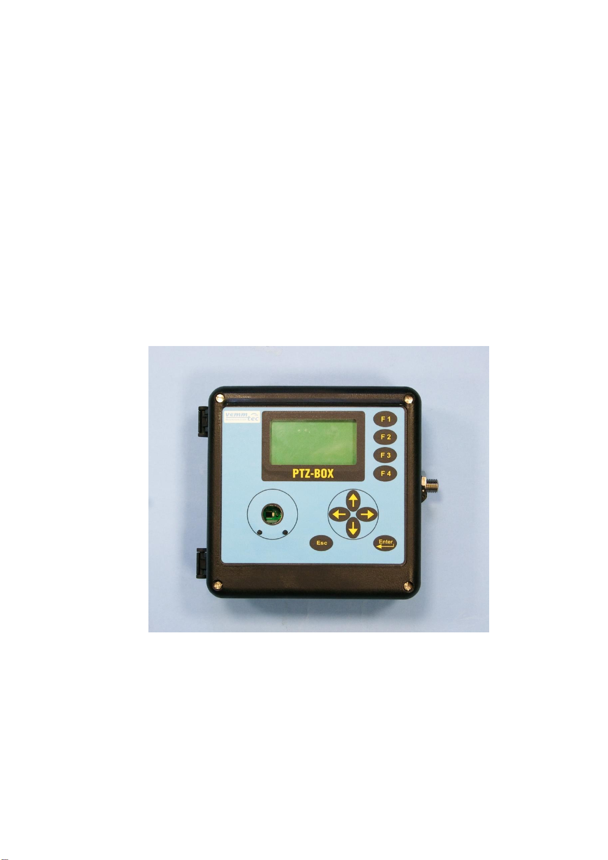
The Electronic gas volume converter PTZ-BOX 3.0 (hereinafter called: “the
device”) is a measuring instrument designed for the conversion of the gas volume
measure at measurement conditions to volume at base conditions.
The information on the gas volume passing through is measured using the
impulse outputs of the gas meter. The gas temperature and pressure are measured
by integrated converters. The device calculates the ratio of compressibility factors of
gas using standard methods or a constant value is used.
The device has been constructed and approved according to the EN 12405-1
standard as a conversion device type 1 (compact system) and can be supplied as a
T, PT, or PTZ conversion device.
From safety point of view the device is constructed according to EN 60079-11
as intrinsic safe.
It is manufactured and supplied in compliance with the following European
Parliament directives:
2014/34/EU Equipment and protective systems for use in potentially explosive
atmospheres
2014/30/EU Electromagnetic compatibility
2014/32/EU Directive on measuring instruments
Device is put on the market and into usage according to above mentioned
standards and is marked with CE mark.
The device is built in a casing with sturdy plastic with IP65 protection. It is
equipped with a graphic display and a 10-button keypad. Furthermore, it has impulse
inputs for the connection of a gas meter with LF or HF impulse output and binary
inputs. The device is also suitable for connection to encoder outputs of a gas meter.
The binary inputs can work as check inputs to check the connection with a gas meter
or can have a different function, e.g. monitoring the conditions of safety snap locks,
doors, etc. The device has 4 available outputs. These can be configured as impulse
or binary outputs, or as data outputs for the CL-1 module. When using this module,
an analogue current output can be realized.
The device is powered by a lithium battery. The life cycle of the battery is 6
years in the standard work mode. An external power supply source can be used in
applications with higher demands.
The device has a data archive of the measured values with an adjustable
structure and storing period. The binary archive stores changes on the binary inputs
and the occurrence of the monitored events (limits, etc.) Error conditions are stored
in a status archive. It is possible to program the storing of important parameters and
calculations and storage of some statistical values in the daily and monthly archive.
The archive has settings for service and metrology; in case of changing the settings,
these settings, as well as the counter values, date and time are recorded. Other
available logs are mentioned in 7.3.

PTZ-BOX 3.0
4
For communication with a superior system, the device has a serial interface
(RS-232 and RS-485). Various communication protocols installed in the device allow
easier connection to SCADA systems. The device cooperates with common phone,
radio, GSM, and GPRS modems, and in case of an alarm condition, it can initiate the
connection.
The device can be extended by one non-metrology sensor for measuring
pressure or temperature. This extension can be performed without breaking the
official mark on an already installed device.
Basic configuration of the PTZ-BOX 3.0 offers:
-analogue input (pressure P - metrological channel)
-analogue input (temperature T - metrological channel)
-4x digital input DI1 to DI4 (binary, pulse); input DI1 can be used for connecting a
NAMUR encoder
-4x digital output DO1 to DO4 (binary, pulse, analogue)
-communication channel RS485/RS232 for communication with superior system
-input of external power supply
-option: connection of one digital pressure sensor PA1.1 or one digital
temperature sensor TA1.1 (non-metrological) to the internal bus via the EDT
expansion board. This extension can be accomplished by the end user on an
already installed device without breaching metrological seals.
The device can be configured using the supplied SW [22] for PCs. This SW also
allows the readout, display and archive of both the immediate measured values as
well as the contents of the internal device archives.
1.2 Function principle
1.2.1 Conversion using the equations of state
The device obtains data on the gas volume via impulses (N) from an LF or HF
sensor located in the gas meter. The volume at the measuring conditions (V) is
calculated from the number of impulses (N) and gas meter constant (kp).
The device obtains other data on the gas from the temperature and pressure
sensors. This data is used to calculate the conversion factor (C) which is influenced
also by: Absolute temperature at base conditions (Tb), absolute pressure at base
conditions (pb) and compressible factor of the gas at base conditions (Zb).
Volume at measuring conditions (operational volume):
V =
N
kp
Ratio of compressibility factor:
K =
Z
Zb
Conversion factor:
C =
p
*
Tb
*
1
pb
(t + 273.15)
K

PTZ-BOX 3.0
5
Volume at base conditions (standardized volume):
Vb= V * C
The gas compressibility factor expresses the deviation of properties of natural
gas from the properties of an ideal gas. By setting the parameters, it is possible to
choose a specific method for calculation of the compressibility factor according to the
standard (AGA NX-19 mod, AGA8-G1, AGA8-G2, SGERG-88 or AGA8-92DC). A
constant compressibility value can be used for other gases besides natural gas. If the
pressure or temperature value gets out of the limits of the validity of the chosen
standard, the device calculates using a default compressibility value.
The device calculates the gas flow from the impulse frequency on the input in
real time using mathematical filtration from the input signal.
Operational flow:
Q = ∆V / ∆t [m3/h]
Where: ∆V ............................ increment of operational volume
∆t ............................. time between the impulses with an accuracy
of one hundredth of a second
The value of the flow displayed on the converter display is updated every 10
seconds.
Standardized flow: Qb= C * ∆V / ∆t [m3/h]
1.2.2 Error values of volumes at measuring conditions and volumes
at base conditions
For calculation during error conditions (i.e. in case of a sensor error, deviation of
the parameter value from the working range, or device error), the device has
counters of the error volume at measuring conditions (Vs) and error volume at base
conditions (Vbs). These counters are interconnected with the pertinent counters of
volume at normal conditions.
A detailed description of device behaviour during normal and error conditions is
in paragraph 4.4.
1.2.3 Volume correction at measurement conditions
Device enables to compensate gas meter error according to predefined
correction curve from gas meter test certificate. This function and parameters Vccan
be activated only by the manufacturer or by an accredited service center to ensure
that the used gas meter correction curve as a function of the flowrate Qm is valid
within the working conditions.
The error of measurement is corrected by using the function f(Qm). The
corrected volume is:
Vc = Vmx f(Qm)

PTZ-BOX 3.0
6
where
Vc
Corrected volume at measurement conditions
Vm
Primary volume
Qm
Primary flowrate
Linear interpolation method is used for getting values between calibration
points. The file with correction values is to be inserted into the device by using the
service software [21]. Information about the insertion of a correction curve into the
device is logged in the setup archive.
The principle of the volume calculation is explained in Fig. 1
Condition for use of volume correction.
1. Correction is possible only in the case that the gas meter transmits at least
10 pulses per second which means the use of HF sensors is required.
2. Under Qmin the correction is not applied and over Qmax the value of the
correction coefficient given for Qmax will be used.
1.2.4 Conversion of volume to energy
The device can calculate the energy content from the consumed quantity of
gas. This conversion uses the value of the combustion heat Hs. The calculation is
made with the differences dVb(and dVbs) multiplied by the actual value of the
combustion heat Hs. dE=Hsx dVb, dEs=Hsx dVbs
Two counters (energy counter E and error energy counter Es) are dedicated for
measurement in units that can be selected to present the value in MJ, kWh or Btu.
No conversion of the absolute counter value (E or Es) is performed after the change
of measurement units. Following increases are added in the new units.
Principle diagram of energy calculation is drawn at Fig. 1
Combustion heat Hs
To get a correct conversion it is necessary to enter the right value of the
combustion heat and the related conditions. Then the device will make a new
conversion of the relative temperature for the defined relative conditions and the final
value will be used for the energy calculation. In case of the AGA8-92DC method the
combustion heat is not entered as a fixed value but calculated from the gas
composition according to EN ISO 6976. For the other methods the value of Hs
(MJ/m3) must be entered manually and always under the conditions:
combustion temperature/ temperature of gas = 25°C / 0 °C

PTZ-BOX 3.0
7
Fig. 1 Volume and energy calculations - Scheme

PTZ-BOX 3.0
8
1.3 Device dimensions
Fig. 2 Device dimensions
2 Device technical description
2.1 Device architecture
The device’s electronics are laid out on three basic boards.
The bottom part of the casing contains the input/output board with the battery
and back-up battery and terminals for connecting the pressure and temperature
sensors and device inputs and outputs. The connections related to the metrological
function of the converter are protected by covers which are secured with official
seals.
Optionally, the input board can have an extension board (EDT port) for
connecting an additional digital pressure sensor (PA1.1) or digital temperature
sensor (TA1.1). This additional digital sensor communicates with the converter using
the Modbus RTU protocol (via RS-485). More information can be found in chapter 17.
The lid of the housing contains a processor board that is protected by a cover
and secured by an official seal. The board cover has an opening for access to the
service switch. The service switch can be used to enable/disable the setting of the
device parameters using a service SW.

PTZ-BOX 3.0
9
Fig. 3 Main parts of the device
2.2 Power supply
2.2.1 Main supply battery
The device is powered by a built-in (lithium) battery with a voltage of 3.6 V. The
life cycle of the battery depends especially on the configuration of the device, the
frequency of communication, and the time the display is on. The consumed capacity
is calculated during the device’s activity and the capacity decrement is recorded in its
memory. The device will issue an alert to replace the battery 90 days before the
expected discharge (error message E9 –see paragraph 9.4.8.
Standard mode for a life cycle of the main supply battery of more than 5 years:
Archiving period of the data archive 1x per hour
Communication with device 2 min/day
Activating the display 2 min/day
Frequency of input impulses ≤10 Hz
Measuring period 15 s
Ambient temperature 25 °C
If the device is operated with higher consumption than in the defined mode, it
is necessary to count on a more frequent replacement of the battery or use a network
power source.

PTZ-BOX 3.0
10
2.2.2 Replacement of main supply battery
It is advised to disconnect a discharged battery as soon as possible. While the
battery is being replaced, the device does not measure pressure or temperature, but
counts the incoming LF impulses (but does not convert the number of pulses, this will
be performed when the supply battery is connected again) and insures that the real
time clock is running. The data stored in the device archives and parameter settings
will remain.
Discharged batteries are in the hazardous waste category. According to
European directives and other internal directives batteries must not be disposed
together with household waste.
2.2.3 Back-up battery
The battery ensures the back-up of important functions in case of the discharge
or replacement of the supply battery. The back-up battery can be replaced in an
accredited service center after the official and security seal is broken (replacement
cannot be performed in a potentially explosive atmosphere). It is necessary to use
the same type of battery: Only recommended battery type may be used.
Standard mode for a life cycle of the back-up battery of 10 years
Storage temperature 25 °C
Backed-up inputs (DI1 –DI4) not connected or connected contacts
disconnected
Does not depend on the presence of the supply battery
Standard mode for a life cycle of the back-up battery of 4 years
Backed-up inputs (DI1 –DI4) short-circuited
Without powering battery
Replacement of main supply battery is allowed in the hazardous area but
only with recommended type of battery.
To correct the calculation of the remaining battery capacity after
replacement it is necessary to reset the battery calculation with service SW
[22]. In the parameter file, select the hardware module and press the button
„Change battery“.

PTZ-BOX 3.0
11
Self-discharging of batteries
The back-up and supply batteries are lithium type. Their capacity drops due to
self-discharging. The recommended time frame for their replacement is 10 years,
even if the battery was never connected.
2.2.4 External power supply
Use of an external power supply is required in case of:
-NAMUR HF pulse input
-Binary output
-NAMUR encoder.
External power supply is recommended in case of increased current consumption
like:
-frequent communication (more than once a day),
-frequent LCD displaying
An approved intrinsically-safe power source must be used for the external
power supply. The internal power sources of the communication modules Kx
Modules can be used if no NAMUR sensors are connected.
If a NAMUR sensor is connected: always use an external power source JBZ-02
or JBZ-01.
12 VDC
EEx
P0
DI 1
DO 4
K3 MODULE
DO 1
DO 2
DO 3
P2
6V OUT
DI 3
DI 2
DI 4
POWER
DI1
DI2
DI3
DI4
INPUTS
DO1
DO2
DO3
DO4
OUTPUTS
PTZ-BOX 3.0
RS232
INPUT T
RS485
INPUT P
INT. BUS (optional) Ex i
POWER
DI1
DI2
DI3
DI4
INPUTS
DO1
DO2
DO3
DO4
OUTPUTS
PTZ-BOX 3.0
RS232
INPUT T
RS485
INPUT P
INT. BUS (optional) Ex i
=12V
=8V
JBZ-02
EEx
12 Vdc
12 Vdc
Hazardous area Safe area
Safe area
Hazardous area
Fig. 4 Examples of external power supply

PTZ-BOX 3.0
12
2.3 Security seals
Security seals located on the device indicate the technical condition of the
device regarding unauthorized handling.
Security seal of the manufacturer (metrological seal)
- its design is stipulated by the Approval certificate on the quality management
system for production, output control, and testing pursuant to Enclosure no. 2,
procedure D, ND no. 464/2005 Coll., issued by the Notified Body no. 1383. Such
security mark has the same importance for the user as the so called official seal
according to the Act on Metrology.
In case such a seal is broken, the manufacturer does not guarantee that the
properties of the device are in compliance with the EC Certificate on type verification.
User seal
- control seal of the user (seals) as needed
Seal of the manufacturer
- control seal of manufacturer as needed
Fig. 5 Security marks

PTZ-BOX 3.0
13
2.4 Product label

PTZ-BOX 3.0
14
3 Safety instructions
3.1 General
The device has been approved according to the guideline 94/9/CE
(2014/34/EU) and an EC certificate on type approval (ATEX) has been issued for its
use in potentially explosive atmospheres. Respecting this guideline is mentioned in
the CE compliance notation.
3.2 Use in potentially explosive atmosphere
Device is fully in compliance with EN 60079-26 ed.2 (see [4]).
Based on the EC certificate in the verification 11 ATEX 0015X, the device can
be operated in potentially explosive atmospheres with a classification of ZONE0.
Indication of the device regarding safety against explosion:
II 1G Ex ia IIC T4/T3
PTZ-BOX 3.0
Zone 0
Environment temperature for temperature class T4: -25 °C to +40 °C
Environment temperature for temperature class T3: -25 °C to +70 °C
When connecting a device, it is necessary to consider the electrical
characteristics of the connecting cables and respect the requirements of the
applicable safety standards. Furthermore, it is necessary respect the Special
conditions of use provided these certificates contain them. The parameters of non-
explosiveness of the device are listed in chapter 13.
3.3 Risks of use
Device cabinet is made of polycarbonate. A keypad foil of polystyrene is placed
on the top cover. In some extreme cases electrostatic charge accumulated on
surface of cabinet could cause explosion. To avoid explosion it is strictly
recommended to keep the following rules:
At hazardous the zones device must not be installed at places where
ambient conditions could create an electrostatic charge.
Device may only be cleaned by humid wiper.
The device has been constructed and approved as intrinsically safe. That
means that only approved devices (intrinsically safe devices, consecutive
devices) or so called simple devices complying with the EN 60079-11 standard
and complying with the intrinsically safe parameters listed in the
EC Certificate on type verification [16] can be connected to the device
connectors.
The applicable safety standards must be met when connecting.

PTZ-BOX 3.0
15
3.4 Special conditions of use
3.5 Using different groups of gas
Individual variants of device can be used only with certain groups of gas
according to this table.
Group of gas
Device variant
IIC
IIB
IIA
PTZ-BOX 3.0
yes
yes
yes
1. The device must not be installed or located in an environment with a
potential danger of electrostatic charge of the device casing (e.g. by
flowing air, etc.) Only a damp cloth must be used if the device is being
cleaned, to prevent the creation of electrostatic charge.
2. Only the following types of batteries are allowed to be used in the device:
Main supply battery: Saft LS33600, Backup battery: Saft LS14250.
Table of contents