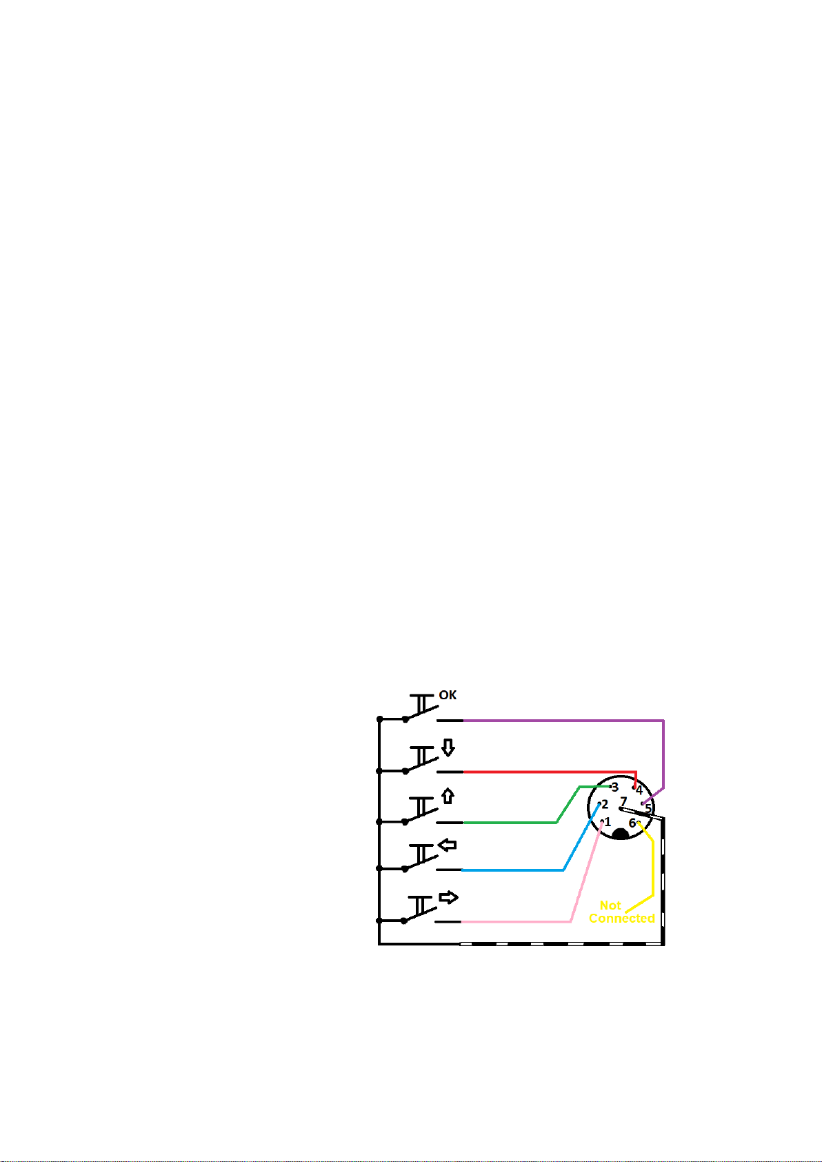
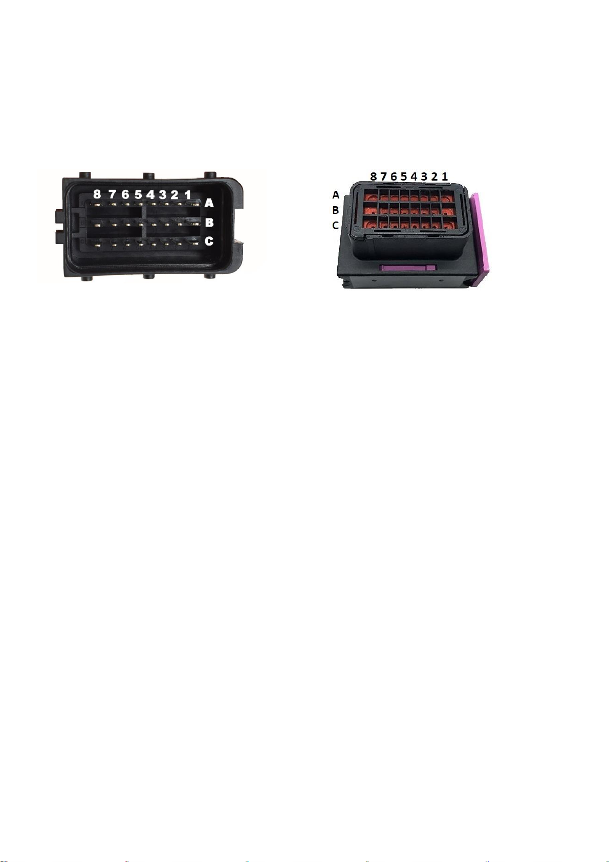
VEMS V3MS DASH7 User manual

for VEMS ECUs
Digital Dashboard for standalone ECUs VEMS V3.x
QUICK GUIDE
For model: HW22/12560N7P
3rd revision 12/2022

Content
1. Introduction
a. Main parts of display unit
2. Electrical connection
a. Display unit
i. Power connector –PWR ( 6 pins )
ii. Control connector –CNTRL ( 7 pins )
b. Main Unit
i. Main unit connector
c. Base connection of DASH7
i. Base connection WIRING DIAGRAM
d. Full connection of DASH7
i. Analog Inputs for 0-5V sensors
ii. Digital Inputs for vehicle lights status (+12V)
iii. Digital inputs switched to Ground
3. Controls
a. Quick access functions
b. Menu navigation
c. Remote control
4. Graphic User Interface
a. GUI update procedure
5. SD Card Full-Datalogger
6. Mounting and Maintenance
a. Mounting
b. Maintenance
7. Troubleshooting
8. Warranty

Introduction
Main parts of display unit:
1. Body
2. 7inch TFT screen
3. Shift-light LED diodes
4. Warning LED diodes
5. Micro SD Card slot
6. Power connector
7. Control buttons connector
8. CR1220 Clock Battery cover
9. Mounting terminals 4x M5

Electrical connection
Display unit
PWR connector ( 6 pins )
This connector is for power supply and communication between main unit and display unit. Without this connector
connected, Dash7 won‘t work. This connector is wired from factory and this pinout is only for troubleshoting
purposes. Do not modify factory wiring harness! Modifying factory harness can cause damage of your Dash7 and will
void a factory warranty!
Power connector pinout:
Pin 1: to main unit connector pin A8
Pin 2: to main unit connector pin A2
Pin 3: to main unit connector pin B7
Pin 4: to main unit connector pin A7
Pin 5: to main unit connector pin A6
Pin 6: to main unit connector pin C7
CNTRL connector ( 7 pins)
This connector is used to control the main functions of display, switching screens, adjusting brightness, hide
warnings, change settings, etc... .
Without this connector connected, the Dash7 will work normally, but you will be unable to control it’s functions or
change settings.
Control buttons are packed in the box with your Dash7. Depends on your order specifications, you can buy separate
buttons, buttons on PCB or buttons in plastic case.
Control connector pinout and wiring diagram:
Pin 1: push button RIGHT (pink wire)
Pin 2: push button LEFT (blue wire)
Pin 3: push button UP (green wire)
Pin 4: push button DOWN (red wire)
Pin 5: push button OK/ENTER (violet wire)
Pin 6: Not In Use (yellow wire)
Pin 7: buttons supply GND - GROUND (white wire
+ black wire + shielding wire twisted together)
WARNING:
These wire colors are not guaranteed and may be changed at any time without notice!
NEVER APPLY ANY VOLTAGE TO THE CNTRL CONNECTOR! Otherwise, you can damage your Dash7!

Main Unit
Main unit connector
Main unit connector is used for Dash7 power supply, ECU communication and for connecting analog and digital
inputs to the Dash7. To disconnect main unit connector pull the violet plastic part to the side and at the same time
pull the connector out from the socket. Connector consists of 3 rows of pins (A, B, C), 8 pins in a row (total of 24
pins)
DO NOT FOLLOW THE POSITION OF A VIOLET PLASTIC PART ON THE PICTURE WHEN INSTALLING PINS,
BECAUSE THIS PART CAN BE MOUNTED IN BOTH DIRECTIONS!
Row A
Pin A1: Sensors +5V supply (load max. 700mA) (NOTE: Pin not connected for Sn2106 or less)
Pin A2: PWR connector of display unit - Pin 2
Pin A3: Sensors GND - Ground supply for sensors (NOTE: Pin not connected for Sn2106 or less)
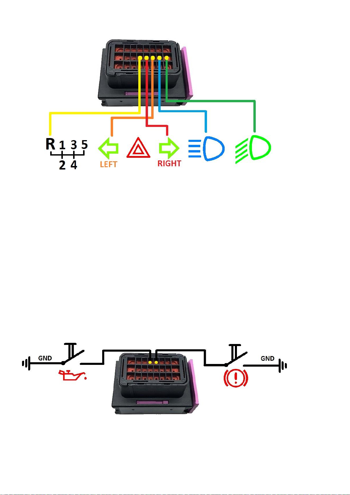
Pin A4: Input 9 (Handbrake - GND) –switch ONLY to GND ! (not protected input)
Pin A5: Input 10 (Oil Press Switch - GND) –switch ONLY to GND ! (not protected input)
Pin A6: PWR connector of display unit - Pin 5
Pin A7: PWR connector of display unit - Pin 4
Pin A8: PWR connector of display unit –Pin 1 (+5V display unit power supply)
Row B
Pin B1: Input 4 (Low Beam Lights +12V) –connect to the +12V of low beam light bulb
Pin B2: Input 5 (High Beam Lights +12V) –connect to the +12V of high beam light bulb
Pin B3: Input 6 (Turn Indicator LEFT +12V) –connect to the +12V of left turn ind. bulb
Pin B4: Input 7 (Turn Indicator RIGHT +12V) –connect to the +12V of right turn ind. bulb
Pin B5: Input 8 (Reverse Gear +12V) –connect to the +12V of reverse light bulb
Pin B6: VEMS Serial RS232 (GND)
Pin B7: PWR connector of display unit - Pin 3
Pin B8: Main Power Supply +12V –connect this pin to the main switch or ignition switch in your car
Row C
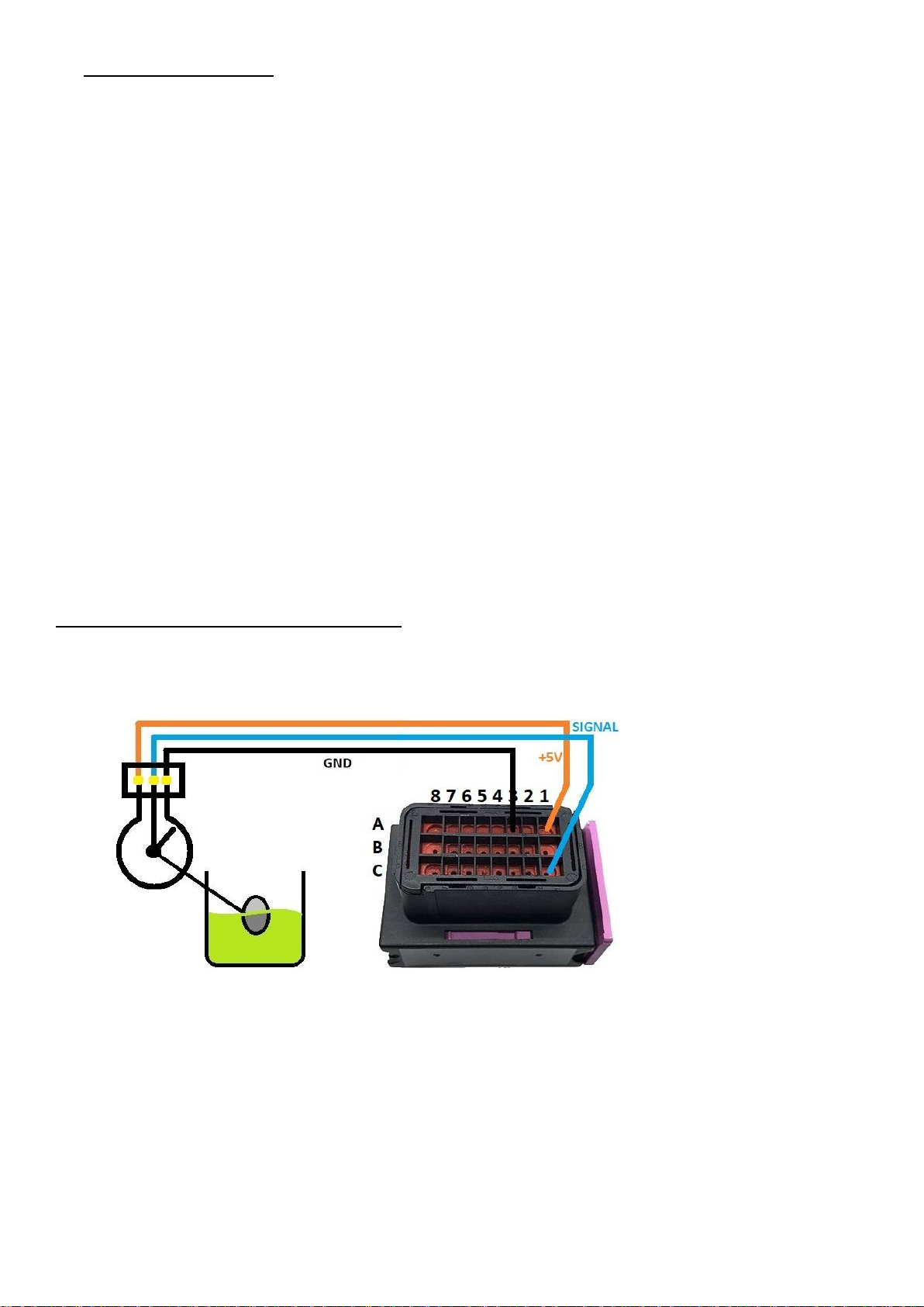
Pin C1: Analog Input 0 (Fuel Level Sensor) –MAX INPUT VOLTAGE 5V ! (unprotected)
Pin C2: Analog Input 1 (Pressure Sensor) –MAX INPUT VOLTAGE 5V ! (unprotected)
Pin C3: Analog Input 2 (Temperature Sensor) –NTC or PTC, MAX INPUT VOLTAGE 5V ! (unprotected)
Pin C4: Analog Input 3 (Configurable Input/Neutral) –any type of sensor, MAX INPUT VOLTAGE 5V ! (unprotected)
Since firmware V7.3.3 and GUI V3.6.2KN Configurable input can be used as Digital Input for Neutral switch
(in this case, connecting to GND means >> Neutral is selected)
Pin C5: VEMS Serial RS232 data (ECU pin EC18/14)
Pin C6: VEMS Serial RS232 data (ECU pin EC18/15)
Pin C7: PWR connector of display unit –Pin 6 (GND of display unit power supply)
Pin C8: Main Power Supply GND –connect to the battery negative terminal or vehicle ground

NOTE: When installing the pins into the connector, always read the numbers and letters on the connector
carefully and double check that all pins are installed in the correct place, as incorrect wiring can damage your
Dash7 !
Base connection of DASH7
Base connection is used when customer want only to visualise data from VEMS ECU without any additional analog
or digital inputs connected to the Dash7.
For base connection just follow these steps:
1. Turn OFF power supply (turn off battery kill switch, main switch,etc...)
2. connect 24pin connector to the main unit of Dash7,
3. connect 6pin connector from main unit to the display unit.
4. plug in Dash7 RS232 cable to the RS232 connector of your VEMS ECU (NOT THE CONNECTOR NAMED LCD!)
5. connect BLACK WIRE from pin C8 of main connector to the vehicle GROUND or battery NEGATIVE terminal
6. connect RED WIRE from pin B8 (through 3A fuse) to the main switch or ignition switch of +12V battery
voltage
If all connections are proper, turn on the power supply. The Dash7 opening ceremony should begin.
Opening ceremony means that the screen of Dash7 will show you Startup screen with “your logo“(or short video),
then you will see a Connect screen for the moment and all LEDs gradually lights up in Red, Green and Blue color. At
the end of the opening ceremony, all the LEDs will go out and the first data page will be displayed with the data from
the ECU.
You can switch between data pages and control the Dash7 by using buttons connected to the CNTRL connector on
the back of the display unit.
The wiring diagram of BASE CONNECTION is on the picture below.
BASE CONNECTION WIRING DIAGRAM OF DASH7

WARNINGS AND NOTES:
-NEVER DISCONNECT ANY CONNECTOR FROM DASH7 WHEN POWER SUPPLY IS ON !
-ALWAYS USE 3 Amp (max 5 Amp) fuse for +12V power supply of Dash7 !
-Locate fuse as close as possible to the main switch (or ignition switch).
-MAKE SURE YOUR GROUNDING IS PROPERLY CONNECTED !
-MAKE SURE ALL CONNECTORS ARE CONNECTED PROPERLY AND LOCKED.
-If possible, always use screws to lock RS232 connector.
-Make sure, you ECU is not „password protected“. If yes, it don’t send any data through the serial
connector (RS232). Your ECU must be „not password protected“ for working with Dash7
-Power supply pins are overvoltage and polarity protected, but we strongly recommend to check all
connections and pinout before turning the power supply ON.
Full connection of DASH7
Full connection means a base connection of Dash7, plus connection of additional inputs.
Inputs
Dash7 can not only visualize data from ECU, but also from its own analog and digital inputs. 0-5V inputs are
unprotected and they tolerate MAXIMUM OF 5 VOLTS ! Higher voltage can damage input or main processor of
Dash7, so be very careful when connecting there inputs. Always use 5V supply from Dash7 if possible. Overvoltage
damage is not covered by factory warranty!
ANALOG INPUTS (FOR 0-5V SENSORS):
Fuel level sensor (3 wires version - potentiometer):
Pin C1: Input signal from Fuel Level Sensor (use 5V and GND supply from Dash7)
Pin A1: +5V sensors power supply (use Pin A8 for Sn2106 or older)
Pin A3: Sensors GND
NOTE: If your sensor has only 2 wires, connect one wire to the Sensors GND (pin A3), another wire to the analog
input (pin C1) and use pull-up resistor between +5V (pin A1) and signal (pin C1). Resistor value must be calculated
and depending on the sensor’s resistance (usually must be more than 1000 Ohm).

Pressure sensor (3 wires version):
Pin C2: Input signal from pressure sensor (0-5V)
Pin A1: +5V sensors power supply (use Pin A8 for Sn2106 or older)
Pin A3: Sensors GND
NOTE: If your sensor has only 2 wires (usually resistance pressure sensors), connect one wire to the GND (pin A3),
another wire to analog input (pin C2) and use pull-up resistor between +5V (pin A1) and the signal (pin C2).
Resistor value must be calculated and depending on the sensor‘s resistance (usually must be more than 1 kOhm).
Temperature sensor (NTC):
Pin C3: Input from Temperature Sensor (NTC or PTC) 0-5V calibrable by curve
Pin A1: +5V sensors power supply
Pin A3: Sensors GND
Connect 2700 Ohm pull-up resistor from pin A1 to pin C3 for most OEM sensors. Or use a value recommended by
sensor’s manufacturer.

Any 0-5V sensor (Configurable input pin):
This input can be used with many types of sensors. For example: Pressure, Temperature, Position,...etc, with 0-5V
output. Or can be used like a digital input for NEUTRAL GEAR SWITCH (since firmware V7.3.3 and GUI V3.6.2KN).
Pin C4: Configurable Input –you can use this input for any sensor connected as shown (as voltage divider 0-5V)
Pin A1: +5V sensors power supply
Pin A3: Sensors GND
NOTE: If your sensor has only 2 wires, connect 1 wire to the GND (pin A3), another wire to the input (pin C4) and
use pull-up resistor between +5V (pin A1) and signal input (pin C4). Resistor value must be calculated and
depending on he sensor‘s resistance (usually must be > 1kOhm). For OEM automotive NTC sensors it is usually
2,7kOhms.
If Configurable input pin is used like a digital input for Neutral switch, connect one side of Neutral switch to the
GND and other side to the input (pin C4) and use pull-up resistor if necessary. Working principle: If Neutral gear is
selected, switch is connected to the GND >>>> “N“ is displayed on the screen of the Dash7 (if Gear gauge is
presented on actual page) and/or Neutral gear LED is turned ON. For proper function you need to go to the
"Gauges" menu and set the "Neutral Gear Channel" from "OFF" to “Conf.Dash In.” (this function is available only
for firmware V7.3.3 and GUI V3.6.2KN or higher)
If you want to use any other device with 0-5V output as a source for this input, connect GND wire from this device
to the GND pin (A3) of the Dash7 and a signal wire (0-5V max) from the device to the pin C4 of the Dash7. Make
sure that the output voltage from the device will never exceed 5 Volts!
NEVER EXCEED 5 VOLTS ON 0-5V ANALOG INPUTS ! IT WILL DAMAGE YOUR DASH7 !

Digital inputs for displaying the vehicle lights status (+12V digital inputs)
Pin B1: Input 4 (Low Beam lights +12V)
Pin B2: Input 5 (High Beam lights +12V)
Pin B3: Input 6 (Turn signal light LEFT SIDE +12V)
Pin B4: Input 7 (Turn signal light RIGHT SIDE +12V)
Pin B5: Input 8 (Reversing lights +12V)
Connect wires directly from positive terminals of the bulbs to the Main unit connector.
When the lights turns ON, indicator on the display or warning LED will also turns ON.
The hazard warning light indicator will automatically turn ON if both sides of the turn signals are flashing.
WARNING: NEVER EXCEED 18 Volts on the +12V digital inputs or it may damage your Dash7. Below 9 volts
(eg. during cranking) these inputs can be unstable and switch from ON to OFF unpredictably.
Digital Inputs switched to Ground (GND digital inputs):
Pin A4: Handbrake input switched to ground
Pin A5: Oil Press Switch switched to ground
When input is connected to the ground, indicator on the screen or LED will turns ON. These inputs has internal pull-
up resistors. These inputs tolerate ONLY GROUND (0 Volt) or MAX +5 Volts!!! Any other voltage will damage your
Dash7!!!

Controls
Quick Access functions
Main controls of display can be reached also while driving (racing) by QUICK ACCESS.
For reaching quick access functions you can use control buttons on remote controller.
NOTE: Please, pay full attention to driving the vehicle and use quick access functions only at the safe places on a race
track !
Quick Acces functions only change parameters, but do not save their values to the memory. So, changes are valide
only till the Dash7 is powered ON. After you turn the device OFF, parameters will be reset to their last saved values.
TIP: If you want to change values (eg. brightness) permanently, change them in the MENU and SAVE them.
Menu navigation
After pushing OK button, you will access the MENU. On every menu page you can navigate cursor by arrows and
confirm (or change color) by OK button. Every menu page is different, so there is a HELP TEXT on every page. Help
text is written in green color and give you an information about the button’s function on the actual page.
Remote control
Remote control buttons can be purchased as individual buttons, buttons on PCB, or plastic-encased buttons. The
plastic case can be mounted anywhere in the interior of the car. In the lower part of this plastic case, the wires come
out. For better integration into the cockpit, the user can choose the orientation of the remote control. So the case
can be installed with the wires exiting at the top, bottom or sides. After mounting the box in the desired position,
you can insert the “OK“button in the correct position. In the menu "Display", you can set the Remote control
orientation to 0°, 90°, 180°or 270°, depending on how you actually mounted it in the car. This function is available
only for GUI V3.6.2KN or higher. Older GUIs use a fixed remote control orientation.

Graphic User Interface (GUI)
Dash7 has unique Graphic User Interface. GUI consists of Startup page with customised logo, Connection page, menu
pages and 5 fully customised data pages. Data pages and Startup page can be completely customised. You can
download templates or create your own design in our V3MS Web Dash Designer. You can use your own logo (picture
or short video) at the Startup page . Also you can add a small logo at any data page you like.
After creating GUI in Web Dash Designer, just send it to us and after validating we will send you a file. Upload this file
to the microSD card, insert the card to the SDcard adapter delivered together with your Dash7, put the adapter to
the Dash7 SDcard port located on the top of the display unit (with QR code or label faced to you) and upload your
new GUI to the device. Below you can find step by step instructions how to perform GUI update.
GUI Update procedure:
1. Turn OFF the Dash7 (turn OFF ignition or another switch which cuts power supply to the Dash7)
2. Insert the microSD card with a new GUI file to the SD card adapter delivered with Dash7 (card must be
FAT32 formatted and the GUI file must be loaded into a root directory)
3. Remove a dust protection cap from SD card slot located at the top of the Dash7 display unit
4. Gently insert SDcard adapter with microSD card to the SD card slot (with QR code or Label faced to you).
A click is heard when the adapter is inserted and the adapter remains locked in the holder.
5. Turn ON Dash7
6. Update will start immediately. You will see a white screen with red letters and numbers. After few
seconds screen will show message „100%“ and „Update Succesfull“
7. Turn OFF Dash7
8. Push gently down the SD card adapter and release it from the display unit
9. After the SDcard was removed, insert a dust protection cap back to its place and turn ON the power
supply of your Dash7
10. Done! Enjoy your new GUI !
NOTE: in some cases, when Dash7 was not updated for a long time, after restart a white screen could be displayed
again with message „firmware upgrade“. It is normal and after few seconds your new GUI will be displayed. If not,
please restart Dash7 again. After restart device should work normal and will display your new GUI.

SD Card Full-datalogger:
If Dash7 was ordered with Full-datalogger, you can save essential data from the ECU to the SD Card during driving.
For start logging only put your SD Card to the slot on a Main unit and set the action when log should start in the
“DATA LOG“menu and restart Dash7. You can set start logging at every startup, or only when engine is running or
only when car is moving. When full-datalog is active, you can see a small icon (Red circle with word REC or Green
circle with word LOG, depending on GUI version) in the corner of your screen. If there is not this icon, conditions for
datalog are not reached or card is not inserted (or card is damaged or incompatible or not formated right).
SD Card must be formated FAT16 or FAT 32 (usually FAT32) . Use only SD card with capacity up to 8GB (some
microSD HC Class10 cards with SD adapter working well up to 32GB).
Files are saved to the SDcard in CSV format which allows you to open these files in many log viewers (eg.
MegaLogViewer) or other software (Excel, Word, Notepad, etc...). Files are named “LogXXXX.csv“, where XXXX is
sequence number from 0000 to 9999 for every new file. Datalogger always check the SDcard and start searching
from number 0000. If the file with that number does not exist, it will create it and starts logging data to that file. For
better clarity, we recommend not deleting the files from the card, but leaving them there until the card is almost full.
If you decide to delete files from the card or copy them to the PC, we recommend doing so with all files so that the
card remains empty. This avoids mixing up files from several days or runs. The data files are compact size (about
6.7MB for 1 hour of recording), so if you have a big enough SD card, you can record on it for several weeks, months
or even years (for 32GB SD card = 4800+ hours = 200 full days). If the number of files on the SD card exceeds 10000,
a "lastlog.csv" file will be created. This file will always be overwritten with the latest data every time the new log will
start.

Mounting and Maintenance
Mounting
Mount the display unit in car interior in a place where you will have an unobstructed view to the screen and LEDs
while driving.
The display unit is designed for mounting to the dashboard panel or holder, using 4x M5 terminals located on the
back side of the unit. Dash7 with COMPOSTIE PLASTIC BODY is using long M5 screws sticking out. Dash7 with
ALUMINIUM BODY is using 4 holes with M5 threat for mounting.
WARNING! When installing Dash7 with an ALUMINIUM BODY, the screws must not be screwed deeper than 10
mm into the body of the display unit. Otherwise, there is a risk of damage to the electronics in the display unit.
Such damage is not covered by the warranty, so always measure the screw clearance before installation! For
installation in materials with a thickness of 1-2 mm, correct screws are included in the package.
The display unit can be placed either in the instrument panel or on a separate holder (not included). When mounting
in a panel, in addition to drilling the mounting holes, it is necessary to drill also holes for connectors, buzzer speaker
and for the battery cover.
When mounting, make sure that there is enough space on the back for the connectors and wiring.
Although the Dash7 main and display units are sealed, it is not considered as rainproof or waterproof device! Using
the device in wet conditions is on customer’s own risk and damage by water (or humudity) is not covered by factory
warranty !
Mounting conditions:
- Before installation, unplug the car’s battery
- If possible, mount the Dash7 on the place where it will not be exposed to a direct sunlight. Do not expose Dash7 to
temperatures above 75 ° C (167 ° F)
- Never mount the Dash7 where it will be exposed to the rain or water!
- Position the cables and connectors in such a way that they cannot be damaged
- Adjust the tilt of the display for the best visibility and lock it in this position
- Place the Dash7 in the holder or panel and tighten the M5 nuts or screws on the back of the Display Unit to max 6
Nm! When installing aluminium body display unit, check the screw clearance first!
- After mounting the display unit, connect the connectors (marked PWR and CNTRL) and secure them by gently
tightening the connector lock nuts
- Mount Dash7 main unit to a flat surface with 2 screws up to 6 mm in diameter (not included)
- Mount the Dash7 Main Unit on the place where it will not be exposed to direct sunlight or other heat sources
(exhaust, heating, etc.). Do not expose to temperatures above 75 ° C (167 ° F)
- Pay attention to the length of the wiring from Main unit to Display Unit and to the Vems ECU
- Ideal location for the main unit is in a horizontal position, but can also be mounted vertically or "upside down"
- Crimp and connect the necessary pins into the connector of the main unit and connect all the necessary wires.
Connect the sensors and inputs first and then the Dash7 power supply
- Position the cables and connectors in such a way that they cannot be damaged or exposed to heat

- Connect the connector to the main unit after thoroughly checking that all wires are connected correctly and
correct fuse is installed on power supply!
- DOUBLE CHECK WIRING AND CONNECTIONS! Some inputs are not short-circuit or overvoltage protected. Some
inputs tolerate only 5 Volts! Higher voltage can (and will) destroy your Dash7 !
IMPROPER CONNECTION MAY DAMAGE OR COMPLETELY DESTROY YOUR V3MS Dash7 !!!
- AFTER DOUBLE CHECKING you can turn ON the ignition (or other switch which turns ON the Dash7). VEMS ECU
should be powered up before of together with Dash7. Otherwise, the connection to the ECU may not be successful.
- Immediately after the power is turned ON, you will see a Startup page with LOGO and Initialization page with
flashing text “INITIALIZING”. When opening ceremony and initializing procedure of Dash7 ends correctly, data from
VEMS ECU will be displayed on your Dash7 screen.
- If everything is working correctly, you can now heat up the heatshrink on the Main unit connector, remove
protective film from the screen, set some parameters in MENU and enjoy your Dash7!
Maintenance
Dash7 does not need during its life any special maintenance. Just keep connectors clean and protected against
corrosion and keep wiring harnesses in good condition. Keep device away from high temperatures, high humidity or
excessive vibrations.
Clean Dash7 body and screen only with wet towel (soft cloth or paper towel) which can’t scratch the surface. NEVER
USE acids, solvents, thinners, gasoline, alcohol and other aggressive cleaning agents for cleaning the Dash7,
otherwise you can totally damage the screen or other part of Dash7.
For long life, if possible, set screen brightness and LEDs brightness to about 50-60% of their full capacity. At 50% this
parts should have a 20 000+ hours service life. Higher brightness shortens their service life rapidly.

TROUBLESHOOTING:
1. Power is turned ON, but the screen is dark and LEDs are OFF: Dash7 probably has no power. Check your
power supply and plug again all connectors. With ignition ON, check if voltage between pins B8 and C8 on
the main connector is the same as battery voltage (usually 12-14V, must not be less than 6 and more than
18V!) and if polarity is not reversed. If there is no voltage, check grounding, fuses and switches. Check if
voltage between pins 1 and 6 of PWR connector is about 5V. If everything is as described, contact our tech
support.
2. Text “INITIALIZING” is flashing more than 3 seconds and message “INITIALIZATION FAILURE” is displayed:
The data connection between the main unit and the display unit is probably missing. Check continuity of the
wiring between the Main Unit and the Display unit (main connector and PWR connector). Plug again all
connectors and secure them on its positions. If everything is as described, contact our tech support.
3. Initialization was successful and you can see data pages, but all gauges shows numbers 888 or 0: There is
probably a missing connection between the Dash7 and the ECU or there is no data coming from the ECU.
Check connection between Dash7 Main unit and VEMS ECU (RS232 connector) and check if the ECU is
powered ON. Check if your ECU is not “PASSWORD PROTECTED”. If yes, disable password protection (or ask
your tuner), because with password protection activated the ECU do not send out any data in Triggerframe
protocol.
4. Dash7 resets while driving or screen flickers: The display unit probably has a low or unstable supply voltage.
Check the quality of the power supply. Check if Dash7 power supply voltage during driving is not dropping
under 8 volts (normally it should be over 12 or 13V). Check the wiring between main unit and display unit
and secure all connectors on its positions. Check if voltage between pins 1 and 6 in the PWR connector is
about 4.8-5.2V while driving. Check if there is not a broken wire between Main unit and the Display unit. If
everything is as described, contact our tech support.
5. I can’t see any OnScreen Warning (OSW) Messages even when values are out of their limits: Probably you
have turned off displaying OnScreen Warning messages. In the menu "Alarms", check that the "OnScreen
Warnings ON/OFF" icon is set to "ON" (icon of the display with a green tick). If not, move your cursor to the
“OSW ON/OFF icon”and press OK button to display the icon with a green tick. You should see a message
“On Screen Warnings ON”. Warning messages can also be turned off temporarily if on some data page the
user presses the "left arrow" button on the remote control. Then a red crossed-out speaker icon will appear
in the corner of the screen. To start displaying the OSW messages again, it is enough if the user presses the
"left arrow" button again (a red crossed-out speaker icon will turn off).
6. I can’t hear any sound when startup or when warning messages are displayed: Probably you have your
buzzer turned off. In the menu "Alarms", check that the "Alarm Buzzer ON/OFF" icon is set to "ON" (icon of
the green speaker). If not, move your cursor to the “Alarm Buzzer ON/OFF icon”and press OK button to
display a green speaker icon. Buzzer can also be turned off temporarily if on some data page the user
presses the "left arrow" button on the remote control. Then a red crossed-out speaker icon will appear in
the corner of the screen. To allow buzzer again, it is enough if the user presses the "left arrow" button again
(a red crossed-out speaker icon will turn off).
7. Buttons on remote control are acting in wrong direction: You probably have the remote control orientation
set incorrectly. Go to menu “Display” and change the orientation setting of remote controller. This function
is available only for GUI V3.6.2KN or higher. Older GUIs use a fixed remote control orientation.
8. Cannot control the Dash7 by buttons on the remote controller: Probably the display unit is not connected
to the buttons or the buttons are faulty. Check if the connector from remote controller (labeled CNTRL) is
connected to the connector CNTRL on the back of the Display unit. Check the continuity between middle pin
(pin7) of CNTRL connector on the display unit and vehicle ground (GND). Unplug CNTRL connector and check
if there is a short circuit between middle pin (pin7) and other pins when you press buttons on the remote
controller. If everything is as described, contact our tech support.
9. GUI update does not start even if the microSD card is inserted in the display unit: If microSD card is
inserted correctly and after restarting the Dash7 starts normally (not on the white Update page), the
microSD card is probably faulty or not properly formatted, not inserted correctly or the card does not have a
valid GUI file (*.tft) or there are more than a one *.tft files on the microSD card. If the card is formatted

FAT32, insert a card into the computer and check if there is a valid GUI *.tft file in the root directory. If not,
format the card again (with FAT32) and then re-upload the tft file to the root directory of the card. Then try
to upload GUI to the Dash7 again. If update does not start or “update failed” message will appear, try
another SD card and repeat the whole process again. In rare cases, the SD card adapter may be faulty, but
usually the problem is faulty or incorrectly inserted SD card. A correctly inserted card means that the
microSD card is inserted in the adapter and the adapter is inserted into the display unit with the QR code
facing the user. A click is heard when the adapter is inserted and the adapter remains locked in the holder.
10. GUI update failed (update failed message on the Update screen): Probably faulty microSD card, try another
card. Even if card is working fine in PC, it can be faulty. If GUI update failed also on other SD cards, GUI file
can be corrupted (very rare). Ask our tech support for a new file.
11. Datalogger is not logging any data, LED on main unit only blink one time: If the LED on the main unit is not
flashing, it means that no data is being written to the SD card. LED blinks one time at startup during
initialization, what only means that the data logger is powered up.
Possible causes are:
oNo SD card inserted or inserted incorrectly. SD card must be inserted upside down and pushed until
a click is heard and card remains locked in holder
oSD card is write-protected. On the side of the SD card is a little switch which can lock the SD card
against writing. Slide this switch to the unlocked position.
oSD card is faulty or not formatted correctly to FAT32. Format the SD card to FAT32 or try another
card.
oData logger is turned OFF or conditions for starting logging have not been reached. Go to menu
“DATA LOG” and check if item “Start of SD card log” is set to “NEVER”. If so, change this setting
according to when you want logging to start. You can set it to: “After power ON”, which start logging
immediately after Dash7 is powered ON. Or you can set it to: “After engine start”, which start
logging when engine RPM are higher than 0. Or you can set it to: “After Wheelspeed1 (or2) > 0“,
which start logging when car speed is higher than zero.
oNo connection between the Dash7 and the ECU, or ECU is turned OFF. If no data is available from
the ECU, the data logger does not log. Connect the ECU and turn it on. When data starts flowing
from the ECU and logging conditions are reached, logging should start. If you have followed all the
steps described above and the problem persists, please contact our tech support.
12. Alarms occurs even if the sensor for the given measurand is not used: This can especially happen when the
sensor for a particular channel is not connected (channel is not in use), because a disconnected sensor
usually means that the input reading will reach its upper or lowest level (eg. -40°C or +155°C). This value is
usually outside safe thresholds and should normally trigger an alarm (because this feature is commonly used
to warn the driver that a connected sensor is faulty or has been accidentally disconnected). A false alarm can
also occur if ECU was disconnected and reconnected or if data from ECU are corrupted (eg. very low voltage
during cranking, etc). If you want to avoid unwanted alarms from not used channel, solution is to set the
thresholds for that measurand to the values which cannot be reached even with disconnected sensor. If this
is not possible for some reason, you can recalibrate the input channel (change upper and lower values to any
safe values, eg. 5V = 30°C and 0V = 40°C). Last way (usually not necessary) is connectiong some resistor (eg.
2.7kOhm) between the input and GND (or +5V) what set the measurand to a fix value.
13. When I connect a laptop to the ECU and disconnect a Dash7, it stops to display data. Can I have connected
both, PC and Dash7 to the ECU at the same time? : Yes, you can have connected your laptop to the Vems
ECU, and at the same time you can watch all data (from ECU and also from Dash7 inputs) on the Dash7, but
you must to use an adapter “Tuning cable” which is available in our shop. This adapter allows you
simultaneously tune your ECU (or log data to the PC or whatever) and display all data and alarms (or also log
data to the SD card) on the Dash7. Without this adapter you can have connected only one device to your
ECU RS232 port (laptop or Dash7).
14. When I was burning data to the ECU via Vemstune, I got OnScreen Waning message on the Dash7: This is
normal and it can’t be completely eliminated. Usually it is a trigger error warning message. It happens
because on a short moment when Vemstune is burning data into the Vems ECU, the data sent from the ECU
to the Dash7 is corrupted.

15. Date and Time displayed on the screen is incorrect: The real-time clock (RTC) battery is probably not
installed or dead. There is a rubber protective cover on the back of the display unit. Under this cover is the
RTC battery holder. Check that the CR1220 battery is correctly installed in the holder. The battery must be
fully inserted and the "+" mark must be visible on the battery. If there is no battery, install a new CR1220
battery in the holder. If there is a battery, but the wrong type or incorrectly installed, remove this battery
and insert a new CR1220 battery in the correct way. If the CR1220 battery is installed correctly, but the time
and date are incorrect after the Dash7 restarts, the battery is probably dead and you need to replace it with
a new one. A very small screwdriver or small extraction tool is usually required to remove the old battery
from the holder.
16. Configurable Input of the Dash7 do not work properly like analog input for temperature or pressure:
Probably this input is now configured as a digital input for the neutral switch. To use the configurable input
as an analog input, you must go to the "Gauges" menu and set the "Neutral Gear Channel" to "OFF". It
disables neutral gear sensing and allows you to now use this configurable input as an analog input for
temperature or pressure. A reboot of Dash7 may be required after changing these settings (this function is
available only for firmware V7.3.3 and GUI V3.6.2KN or higher).
17. Speed 1 or Speed 2 gauge still shows 0 kmh or mph even if car moves: You probably don't have a wheel
speed sensor connected to the wheel speed input of the Vems ECU, or the sensor is not properly calibrated
or faulty or installed incorrectly. Calibration of the wheel speed sensor must be performed in the Vems ECU
via Vemstune software. The Dash7 only reads wheel speed values from the ECU and therefore no
configuration is required in the Dash7.
18. Gear gauge still shows “N” or “R” even when another gear is engaged: Probably Reverse gear input or
Neutral gear input (Dash7 configurable input) are shorted to ground or their voltage is under 3 Volts. It could
be a wiring problem or faulty switch. Check function of reversing lights switch on the gearbox. If faulty,
change the switch, if not, check your wiring for short-circuits to ground. Same with the Neutral gear switch
(connected to the Dash7 Configurable input pin). Check if you are not using Configurable input pin for
another purpose (pin connected to the pressure or temperature sensor, etc…). If yes, you need to go to the
"Gauges" menu and set the "Neutral Gear Channel" to "OFF". It disables neutral gear sensing and allows you
to use this Configurable input as an analog input for temperature or pressure. A reboot of Dash7 may be
required after changing these settings (this function is available only for firmware V7.3.3 and GUI V3.6.2KN
or higher). If your Neutral gear or Reverse gear inputs are not connected to the harness (not in use) and Gear
gauge shows “N” or “R” (very rare case), you can try to add some pull-up resistor (eg. 2.7kOhm) between the
input pin and +5V sensors supply pin. If you have followed all the steps described above and the problem
persists, please contact our tech support.
19. Oil press, Fuel press or Oil temp gauge in Dash7 is showing different value than in Vemstune: Probably
your Oil pressure, Fuel pressure or Oil Temperature channels in the Dash7 are not calibrated correctly. You
need to go to the "Gauges" menu and select the “Press channels calibration” or “Temp channels calibration”
button. Then if you press the OK button on the remote control, you will be taken to the calibration page,
where you can set a source channel for that pressure or temperature gauge. As a source you need to select
the ECU analog channel to which your sensor is wired. Then set voltage and pressure (or temperature)
values depending on the sensor manufacturer’s datasheet (or Vemstune data). If everything is set correctly,
exit the menu and you should see the correct value on your pressure or temperature gauge.

Warranty
Factory standard limited warranty is 24 months from the date of delivery.
Warranty covers manufacturing defects and damages created during production or packaging. Warranty
does not cover the damage of the device by over-current, over-heating, over-voltage, under-voltage of the
device and its inputs, also does not cover any mechanical or electrical damages made by consumer or third
parties, or by natural disasters, damages caused by water or other liquids entering the device (device and
it’s accessories are not waterproof or water resistant!), damages made by improper installation, extreme
conditions, improper usage of the device, wear or by the car accident. Dash7 is product which requires
professional installation by an experienced technician. Failure to do so may void the warranty. Warranty
also does not cover damages or defects created during shipping.
Warranty is also void if the seals have been broken, if anyone has opened or modified the device or its
accessories!
All warranty repairs or modifications must be performed by the manufacturer or its authorized service, otherwise
the product will void the warranty.
------------------------------------------------------------------------------------ ----------------------------------------
Stamp and signature of the workshop that installed this device Date of installation
----------------------------------------------------------------------------------- ----------------------------------------
Vehicle: type, VIN Dash7 Serial number
All information in this manual is for informational purposes only, may not be considered immutable and the
manufacturer reserves the right to change these informations or device specifications at any time without prior
notice.
The manufacturer is not liable for any damage caused by improper use, improper connection, improper installation
or modification of the device.
The information in this manual must not be considered binding and the installation must be carried out by a
professionally trained person trained in working with automotive electronics and electronic devices.
This manual is valid for 2021 and 2022 Spec devices only.
This is the 3rd revision of this document, published 12/2022.
Copyright ITALPOL RACING, Slovakia 2022, V3MS Motorsport Solutions
Table of contents
Other VEMS Automobile Accessories manuals
Popular Automobile Accessories manuals by other brands

Roadmaster
Roadmaster 751428 installation instructions

Caltrend
Caltrend CR174 installation instructions

Raptor Series
Raptor Series MAGNUM RT GTS65TY manual

Fabtech
Fabtech FTS22111 installation instructions

Volvo
Volvo 31210148 installation instructions

Whelen Engineering Company
Whelen Engineering Company Freedom Mini Edge installation guide