BD Diesel Performance Monitor Cool Engine Shutdown User manual
5/11/2006 1081100 Cool Engine Shutdown Page 1
BD Engine Brake Inc.
Plant Address: Unit A10, 33733 King Rd, Abbotsford, BC, Canada V2S 7M9
U.S. Shipping Address: 88-446 Harrison St, Sumas, WA 98295 U.S. Mailing Address: P.O. Box 231, Sumas, WA 98295
Phone: 604-853-6096 Fax: 604-853-8749 Internet: www.bd-power.com
C
Co
oo
ol
l
E
En
ng
gi
in
ne
e
S
Sh
hu
ut
td
do
ow
wn
n
I
In
ns
st
ta
al
ll
la
at
ti
io
on
n
I
In
ns
st
tr
ru
uc
ct
ti
io
on
ns
s
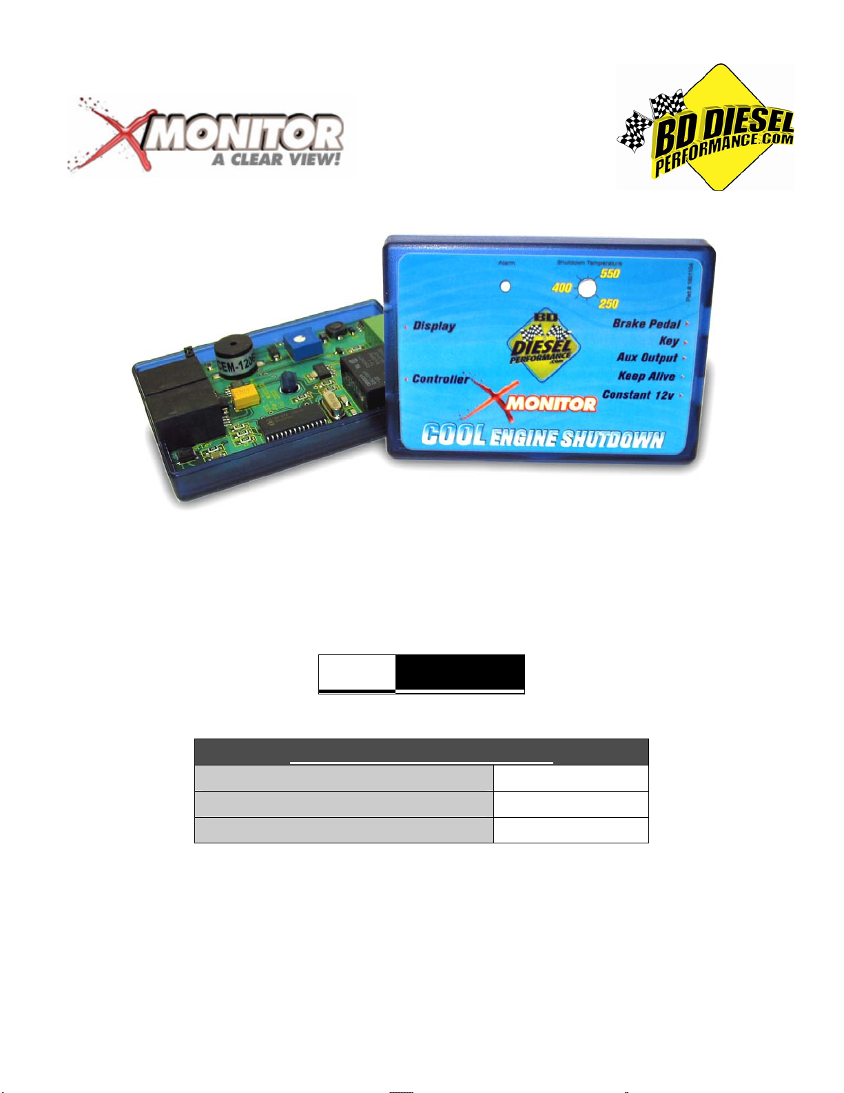
Part# 1081100
An X-Monitor Xcessory for:
Dodge Cummins 1994-2006
Ford Powerstroke (6.0/7.3L) 1999-2006
GMC/Chevy Duramax 2001-2006
*** Please read this manual before starting installation. ***
OWNER’S MANUAL - LEAVE IN GLOVE BOX
Install Manual Part # I1081100
Printed in Canada

5/11/2006 1081100 Cool Engine Shutdown Page 2
BD Engine Brake Inc.
Plant Address: Unit A10, 33733 King Rd, Abbotsford, BC, Canada V2S 7M9
U.S. Shipping Address: 88-446 Harrison St, Sumas, WA 98295 U.S. Mailing Address: P.O. Box 231, Sumas, WA 98295
Phone: 604-853-6096 Fax: 604-853-8749 Internet: www.bd-power.com
TABLE OF CONTENTS
Welcome.......................................................................................................3
Kit Contents.................................................................................................3
Required Tools............................................................................................3
Accessory Options......................................................................................3
Compatibility................................................................................................4
Notes on Connectors..................................................................................4
What is the COOL ENGINE SHUTDOWN (CES)?......................................4
How does the COOL ENGINE SHUTDOWN work?...................................5
Precautions..................................................................................................5
Safety Features............................................................................................5
Audible Alarm..............................................................................................6
Wiring...........................................................................................................6
FORD POWERSTROKE WIRING DIAGRAM ......................................................8
DODGE CUMMINS WIRING DIAGRAM...............................................................9
DURAMAX WIRING DIAGRAMS........................................................................10
Wastegate Solenoid Power Harness (2004½-05 Dodges Only) ............12
Temperature Adjustments........................................................................13
Communication / Operation Lights .........................................................13
Mounting....................................................................................................13
Optional LED Alarm ..................................................................................13
Wire Color Glossary..................................................................................14
Questions?.................................................................................................15
LIMITED WARRANTY STATEMENT.........................................................16

5/11/2006 1081100 Cool Engine Shutdown Page 3
BD Engine Brake Inc.
Plant Address: Unit A10, 33733 King Rd, Abbotsford, BC, Canada V2S 7M9
U.S. Shipping Address: 88-446 Harrison St, Sumas, WA 98295 U.S. Mailing Address: P.O. Box 231, Sumas, WA 98295
Phone: 604-853-6096 Fax: 604-853-8749 Internet: www.bd-power.com
Welcome
Thank you for purchasing the Cool Engine Shutdown accessory for your BD X-Monitor.
This manual is divided into different areas to assist you with your installation and
operation of this unit. If there is any missing parts or if you have technical questions
about this product then please phone our tech-line at (800) 887-5030.
Kit Contents
•Qty. 1 - Cool Engine Shutdown Module
•Qty. 1 - 5-Terminal Connector (for module)
•Qty. 1 - 18” Communications Cable
•Qty. 36” - Tan Wire
•Qty. 36” - Pink Wire
•Qty. 36” - Green Wire
•Qty. 36” - Blue Wire
•Qty. 4 - Gray Posi-Tap (18-22ga) Connector
•Qty. 4 - Black Posi-Tap (12-18ga) Connector
•Qty. 2 - Green Posi-Tap (10-12ga) Connector
Required Tools
•Wire strippers
•Wire crimpers
•Pliers (Needle or Flat Nose)
•Small flat nose screwdriver
•Soldering gun (optional)
•Heat shrink or liquid tape (optional)
Accessory Options
•1081120 - Red LED Alarm Kit
•1081123 - Amber LED Alarm Kit
NOTE: The ground terminals of the vehicle’s batteries should be disconnected before
performing any taping onto any ECM/PCM wire.

5/11/2006 1081100 Cool Engine Shutdown Page 4
BD Engine Brake Inc.
Plant Address: Unit A10, 33733 King Rd, Abbotsford, BC, Canada V2S 7M9
U.S. Shipping Address: 88-446 Harrison St, Sumas, WA 98295 U.S. Mailing Address: P.O. Box 231, Sumas, WA 98295
Phone: 604-853-6096 Fax: 604-853-8749 Internet: www.bd-power.com
Compatibility
If the X Monitor displays the two (2) readouts “PYRO” and “TURBO” only and is version
1.xx or 2.xx, the module and display will have to be updated so the CES will be
compatible. Call 1-800-887-5030 and ask for the claims division to arrange for this
update. All other units that display three (3) measurements do not need upgrading.
Notes on Connectors
The kit includes a number of Posi-Tap™ connectors (Gray/Black/Green) to tap onto
OEM wiring. It is important to select the correct color of connector so that it matches
the gauge of the OEM wire that it is being installed on. Using the incorrect connector
could cause an inadequate connection and/or the OEM wire could be severed.
OEM Wire Posi-Tap™ Color
18-22ga Gray or Red
12-18ga Black
10-12ga Green or Yellow
Though these connectors offer a quicker installation, the best option would be to solder
the wires and isolate the joints with heat shrink or liquid electrical tape. Proper
soldering techniques should be used to ensure adequate connections.
Posi-Tap™ Connector Usage Diagram
Insert Hot Wire Tighten Strip Leads Insert & Tighten
Make sure to center the wire when tightening the pierced portion of the hot wire to make a solid connection.
What is the COOL ENGINE SHUTDOWN (CES)?
The CES is designed to keep the engine running when the ignition key is turned off
and the exhaust temperature is above a set point (between 250-550°F) to prevent
turbocharger bearing failure that could occur when the engine is shutdown too quickly.
A typical turbocharger can spin in excess of 100,000rpm under load, which will
continue spinning when the engine is turned off.
The turbocharger is lubricated and cooled by engine oil - when the engine is turned off,
that oil supply is cut off. If a turbocharger is still spinning at a high RPM when the oil
supply is cut off, the internal bearings will utilize what remaining oil is left around them

5/11/2006 1081100 Cool Engine Shutdown Page 5
BD Engine Brake Inc.
Plant Address: Unit A10, 33733 King Rd, Abbotsford, BC, Canada V2S 7M9
U.S. Shipping Address: 88-446 Harrison St, Sumas, WA 98295 U.S. Mailing Address: P.O. Box 231, Sumas, WA 98295
Phone: 604-853-6096 Fax: 604-853-8749 Internet: www.bd-power.com
then start to heat up, essentially cooking the oil which causes premature bearing
failure. By allowing the turbocharger to slow down to a safe RPM, this bearing failure
can be prevented. An efficient means of gauging a safe time to turn the engine off is by
the exhaust temperature.
A good temperature range to go by is when a turbocharger is below 400°F (with the
thermocouple mounted post-turbo) it is safe to turn off the engine. The further away
the probe is away from the turbocharger, the shut-off temperature should be lower. If
the thermocouple is mounted pre-turbo, then the shut-off temperature can be higher.
How does the COOL ENGINE SHUTDOWN work?
The CES module utilizes the data being transmitted between the X-Monitor controller
and display to constantly monitor the exhaust temperature. When the key is turned off
and the exhaust temperature is above the shutdown setting, the CES module will keep
power supplied to the ECM/PCM, which in turn will keep the engine running until the
temperature falls below the setting.
Precautions
The CES will not lock the doors or set the alarm. With most vehicles, once you shut
the door you can use the keyless remote or key to lock the doors.
Most OEM and aftermarket alarms will have to be activated after the CES has
shutdown the engine. Due to the wide variety of the alarms and immobilizers, it is best
to test the system(s) thoroughly to ensure proper procedures of activation or use in
conjunctions with the CES.
Proper parking procedures should be adhered to before leaving the vehicle including
the engagement of the parking brake. Children or animals should not be left
unattended in the vehicle while the CES is keeping the vehicle running.
Safety Features
The CES module has a few safety features built in that the driver should be aware of.
If for some reason the exhaust temperature does not fall below of shutdown setting
within five (5) minutes from the key being turned off, the CES will automatically
shutdown the engine.
The CES module is also designed to monitor the vehicle’s hydraulic brakes when it is
connected to the brake pedal switch via the Brake Pedal terminal on the module.
While the CES module is keeping the engine alive (ignition key turned off and exhaust
temperature above the shutdown setting), if the brake pedal is depressed the CES will
5/11/2006 1081100 Cool Engine Shutdown Page 6
BD Engine Brake Inc.
Plant Address: Unit A10, 33733 King Rd, Abbotsford, BC, Canada V2S 7M9
U.S. Shipping Address: 88-446 Harrison St, Sumas, WA 98295 U.S. Mailing Address: P.O. Box 231, Sumas, WA 98295
Phone: 604-853-6096 Fax: 604-853-8749 Internet: www.bd-power.com
shutdown the engine. This was implemented to protect the vehicle from being stolen
when the engine is in cool down mode; eventually the brake pedal would have to be
pressed which will shutdown the engine preventing the thief from easily driving away
with the vehicle. This is also useful in situations where the engine needs to be
shutdown immediately or is desired to be shutdown sooner.
Audible Alarm
As an added bonus to the engine shutdown function of the CES, there is an audible
alarm built into the module. While monitoring the data between the X Monitor
controller and display for the exhaust temperature, the CES also is looking for any
registered alarms flashing on the display. When the alarm is flashing, the CES module
will emit a repeating tone that will stop when the alarm stops flashing on the display.
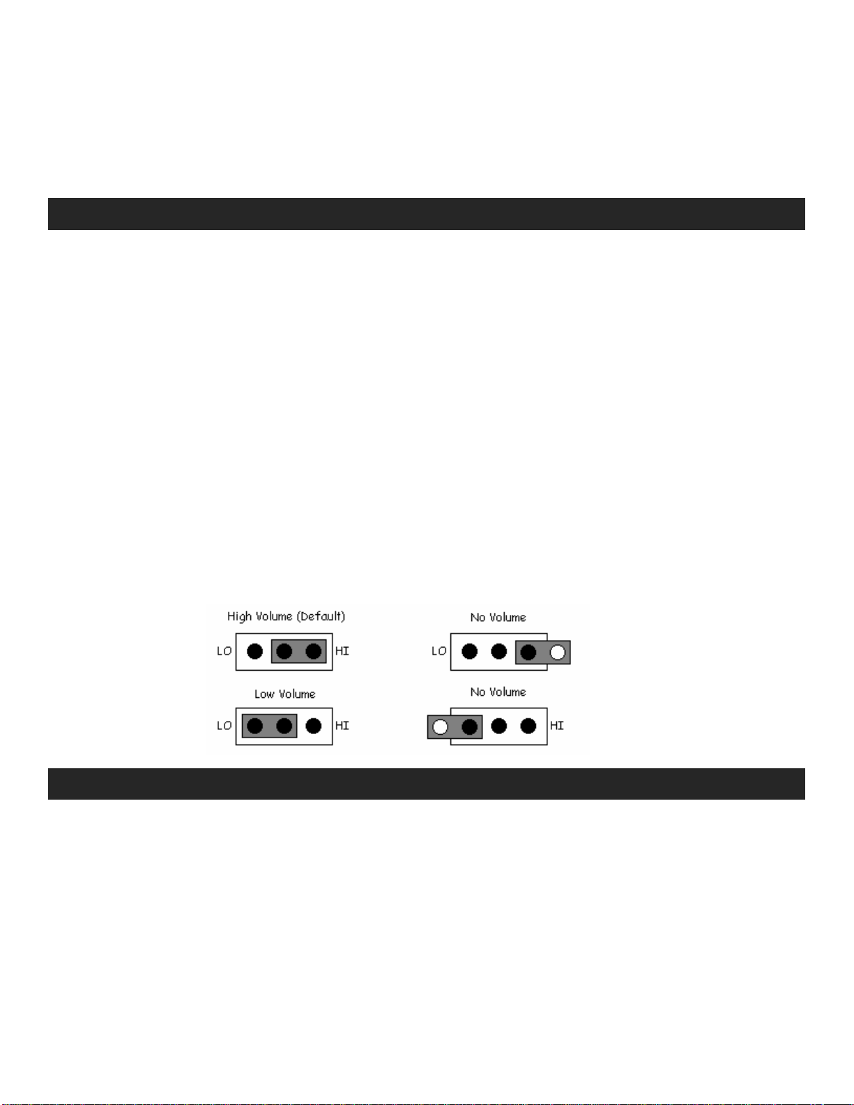
There are three volume settings for the audible alarm: high (default), low and off.
The volume of the audible alarm is can be adjusted by a jumper setting inside the
module. To do this, with the communication cables and the 5-terminal connector
unplugged, remove the screw on the back of the module and take the top cover off. In
the upper left section of the board, near the display communication connector, there is
a 3-pin connector with a jumper.
For high and low volume the jumper will connect the center pin and one the two (2)
outer pins marked “HI” and “LO”. For no alarm, place the terminal on either one of the
outer pins and away from the center pin.
Wiring
Disconnect the communication cable from the X Monitor controller that leads to the
display and insert into the port marked “Display” on the CES module. Utilizing the 18”
communications cable supplied with the CES module, plug one end into the port
marked “Controller” on the CES module and the other end into the display port on the
X Monitor controller.
Using the following charts, tap onto the vehicles wires using the appropriate sized
Posi-Tap connector (not necessary if soldering the connections). All the vehicle wires
are located under the dash.

5/11/2006 1081100 Cool Engine Shutdown Page 7
BD Engine Brake Inc.
Plant Address: Unit A10, 33733 King Rd, Abbotsford, BC, Canada V2S 7M9
U.S. Shipping Address: 88-446 Harrison St, Sumas, WA 98295 U.S. Mailing Address: P.O. Box 231, Sumas, WA 98295
Phone: 604-853-6096 Fax: 604-853-8749 Internet: www.bd-power.com
Strip one end of each CES wire and attach a male blade connector to one end of each
wire (not necessary if soldering the connections). Connect the wires to the Posi-Taps
and run the free ends to the CES module, keeping clear of moving or heat-generating
devices. Excess wire can be trimmed but please keep in mind that the module may
have to be accessed to adjust the shutdown temperature or be removed to adjust
alarm volume, so, we suggest leaving enough slack to perform these functions.
Strip each end of the wires and connect to the appropriate terminals on the 5-terminal
connector as per the charts and diagrams. Tighten each terminal by turning the
terminal screws clockwise until the wire is secure. Plug the 5-terminal connector into
the CES module and leave the module in a location where it can be accessed for
adjustments before final mounting.
NOTE: The 12v-power wire for the X Monitor module must be connected to the same
line as the “Keep Alive” is connected (See applicable chart for your application on
pages 8-12). Connect the power lead for the X Monitor module to the same “Keep
Alive” terminal on the CES module.

5/11/2006 1081100 Cool Engine Shutdown Page 8
BD Engine Brake Inc.
Plant Address: Unit A10, 33733 King Rd, Abbotsford, BC, Canada V2S 7M9
U.S. Shipping Address: 88-446 Harrison St, Sumas, WA 98295 U.S. Mailing Address: P.O. Box 231, Sumas, WA 98295
Phone: 604-853-6096 Fax: 604-853-8749 Internet: www.bd-power.com
FORD POWERSTROKE WIRING DIAGRAM
Ford Connector 1994-2004 Fords
2005+ Fords
Connect the black wire to a good grounding point.
Model Location OEM Wire Pin
Brake Pedal (Blue Wire)
1994-2003 7.3L GN
2003-2006 6.0L Brake Pedal Switch RD/GN
Key (Green Wire)
1994-1997 7.3L BK/LG 297 A1
1999-2003 7.3L Ignition Connector C269 RD/BK 1040 A3
2003-2004 6.0L RD/BK 1040 A3
2005-2006 6.0L Ignition Connector C250 RD/BK 1040 13
Keep Alive (Tan Wire)
1994-1997 7.3L RD/LG 16 I1
1999-2001 7.3L RD/BK 1000 I1
2002-2003 7.3L Ignition Switch Harness RD/LG 16 I1
2003-2004 6.0L WH/YL 1044 I1
2005-2006 6.0L Ignition Connector C250 RD/LG 16 1
Constant (Pink Wire)
1994-2003 7.3L Ignition Switch Harness YE 37 B1 or B3
2003-2004 6.0L YE 37 B1 or B3
2005-2006 6.0L Ignition Connector C250 YE 37 7
5/11/2006 1081100 Cool Engine Shutdown Page 9
BD Engine Brake Inc.
Plant Address: Unit A10, 33733 King Rd, Abbotsford, BC, Canada V2S 7M9
U.S. Shipping Address: 88-446 Harrison St, Sumas, WA 98295 U.S. Mailing Address: P.O. Box 231, Sumas, WA 98295
Phone: 604-853-6096 Fax: 604-853-8749 Internet: www.bd-power.com
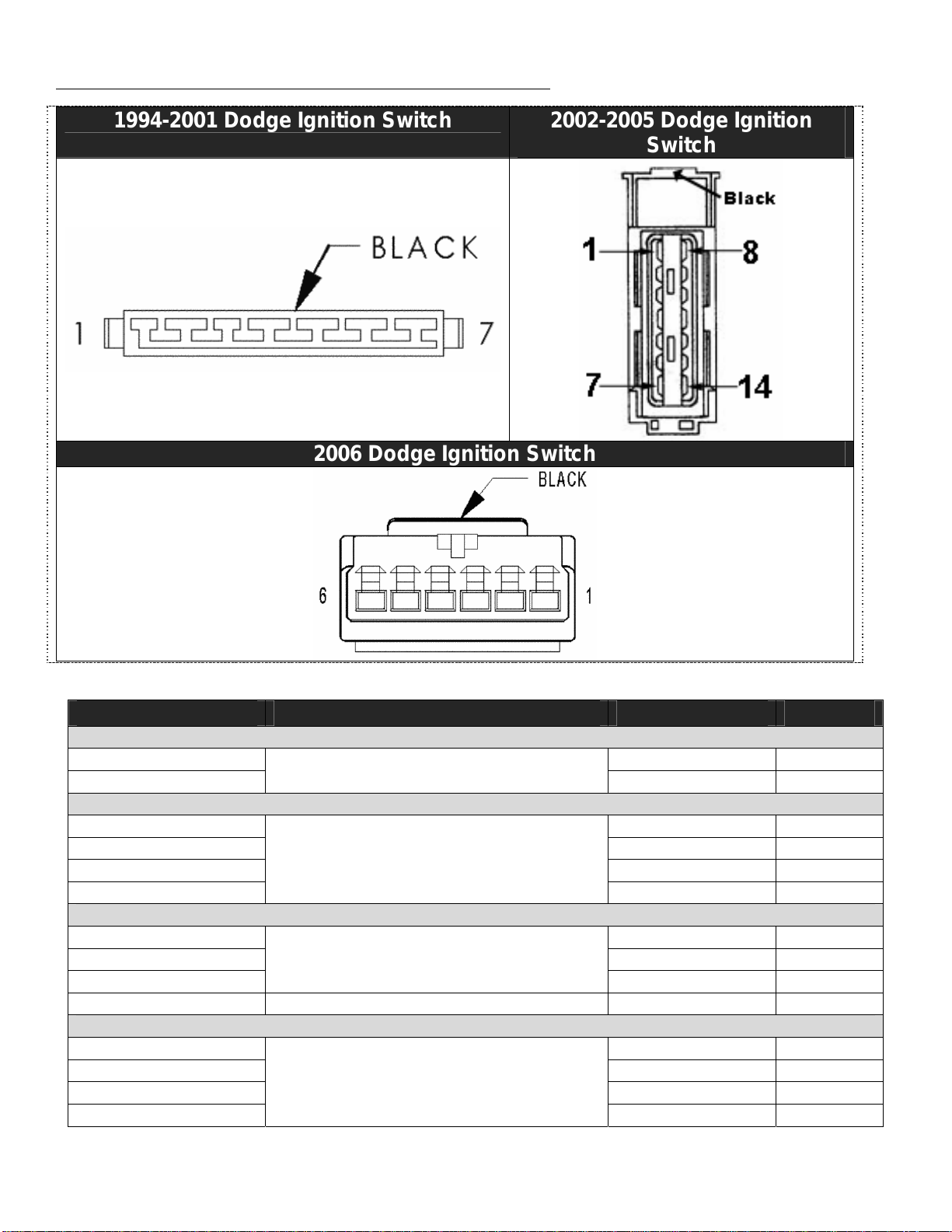
DODGE CUMMINS WIRING DIAGRAM
1994-2001 Dodge Ignition Switch 2002-2005 Dodge Ignition
Switch
2006 Dodge Ignition Switch
Connect the black wire to a good grounding point.
Model Location OEM Wire Pin
Brake Pedal (Blue Wire)
1994-2001 WT/TN L50
5
2002-2006 Brake Pedal Switch WT/TN L50 2
Key (Green Wire)
1994-2002 BK/OR A22
5
2003 BK/WT A31
9
2004-2005 PK/YL F982
9
2006
Ignition Switch Harness
PK/WT F20 3
Keep Alive (Tan Wire)
1994-2002 DB A21
2
2003 DB A21
3
2004-2005 Ignition Switch Harness PK/LG F951 3
2006 ECM Connector (C2) PK/GY 32
Constant (Pink Wire)
1994-2002 RD A1 7
2003 RD A1 4
2004-2005 RD A951 4
2006
Ignition Switch Harness
LB/RD A106 6
5/11/2006 1081100 Cool Engine Shutdown Page 10
BD Engine Brake Inc.
Plant Address: Unit A10, 33733 King Rd, Abbotsford, BC, Canada V2S 7M9
U.S. Shipping Address: 88-446 Harrison St, Sumas, WA 98295 U.S. Mailing Address: P.O. Box 231, Sumas, WA 98295
Phone: 604-853-6096 Fax: 604-853-8749 Internet: www.bd-power.com
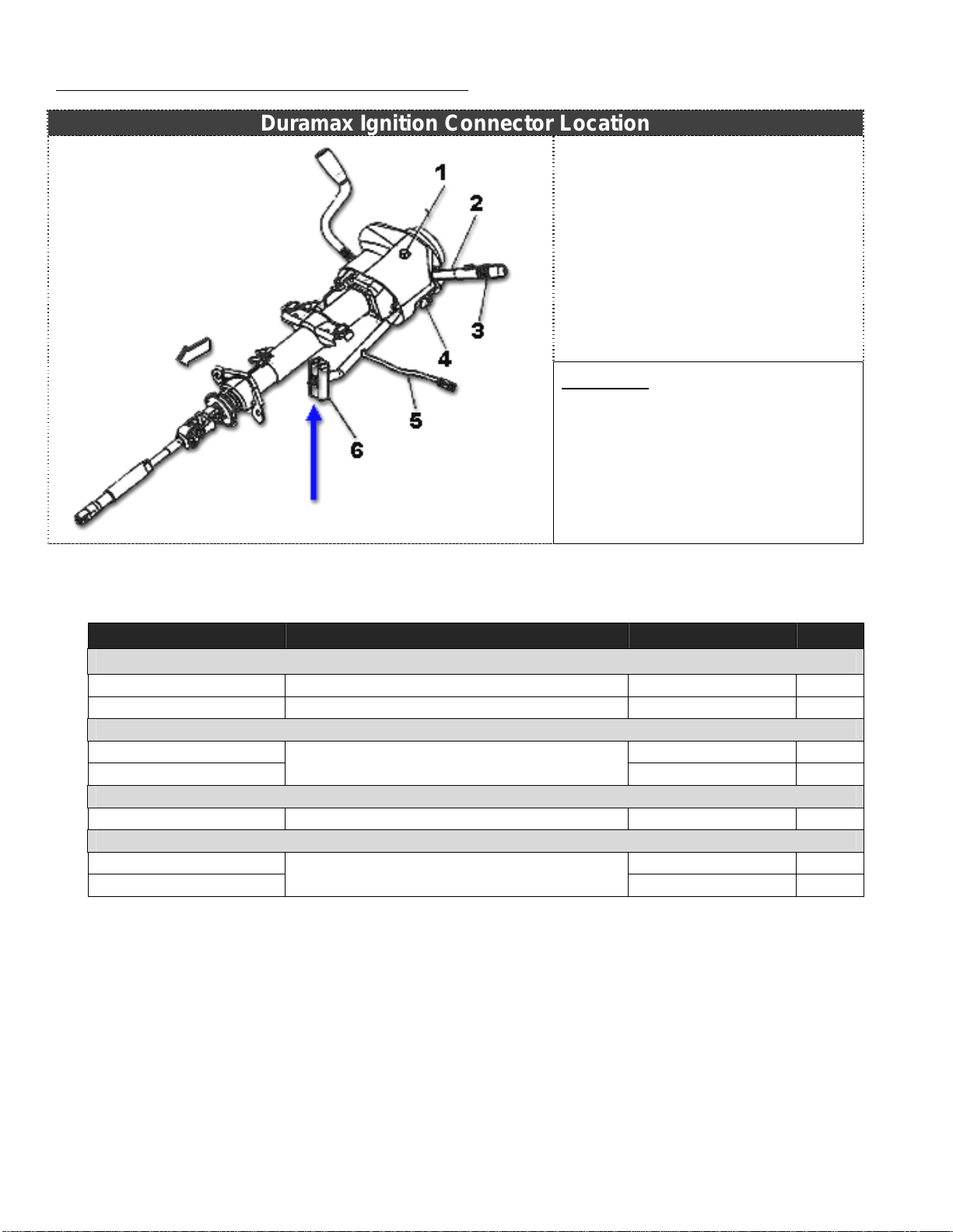
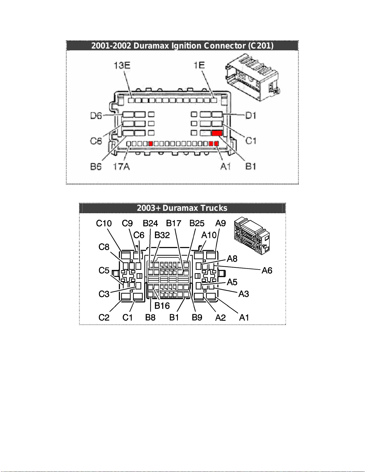
DURAMAX WIRING DIAGRAMS
Duramax Ignition Connector Location
Legend
1. Hazard Button
2. Multi-Function Lever
3. Cruise Control Switches
4. Tilt Steering Actuator
5. Inflatable Restraint Harness
6. C201 Inline Connector
Connect the black wire to a good grounding point.
Model Location OEM Wire Pin
Brake Pedal (Blue Wire)
2001-2002 Ignition Connector C201 WT 17 A1
2003-2006 Brake Pedal Connector WT 5689 2
Key (Green Wire)
2001-2002 BRN 41
A13
2003-2006 Ignition Connector C201 BRN 41 B18
Keep Alive (Tan Wire)
2001-2006 Ignition Connector C201 PNK 139 A2
Constant (Pink Wire)
2001-2002 RD 242 B1
2003-2006 Ignition Connector C201 RD 342 C1
5/11/2006 1081100 Cool Engine Shutdown Page 11
BD Engine Brake Inc.
Plant Address: Unit A10, 33733 King Rd, Abbotsford, BC, Canada V2S 7M9
U.S. Shipping Address: 88-446 Harrison St, Sumas, WA 98295 U.S. Mailing Address: P.O. Box 231, Sumas, WA 98295
Phone: 604-853-6096 Fax: 604-853-8749 Internet: www.bd-power.com
DURAMAX WIRING DIAGRAMS (cont’d)… ---
2001-2002 Duramax Ignition Connector (C201)
2003+ Duramax Trucks
5/11/2006 1081100 Cool Engine Shutdown Page 12
BD Engine Brake Inc.
Plant Address: Unit A10, 33733 King Rd, Abbotsford, BC, Canada V2S 7M9
U.S. Shipping Address: 88-446 Harrison St, Sumas, WA 98295 U.S. Mailing Address: P.O. Box 231, Sumas, WA 98295
Phone: 604-853-6096 Fax: 604-853-8749 Internet: www.bd-power.com
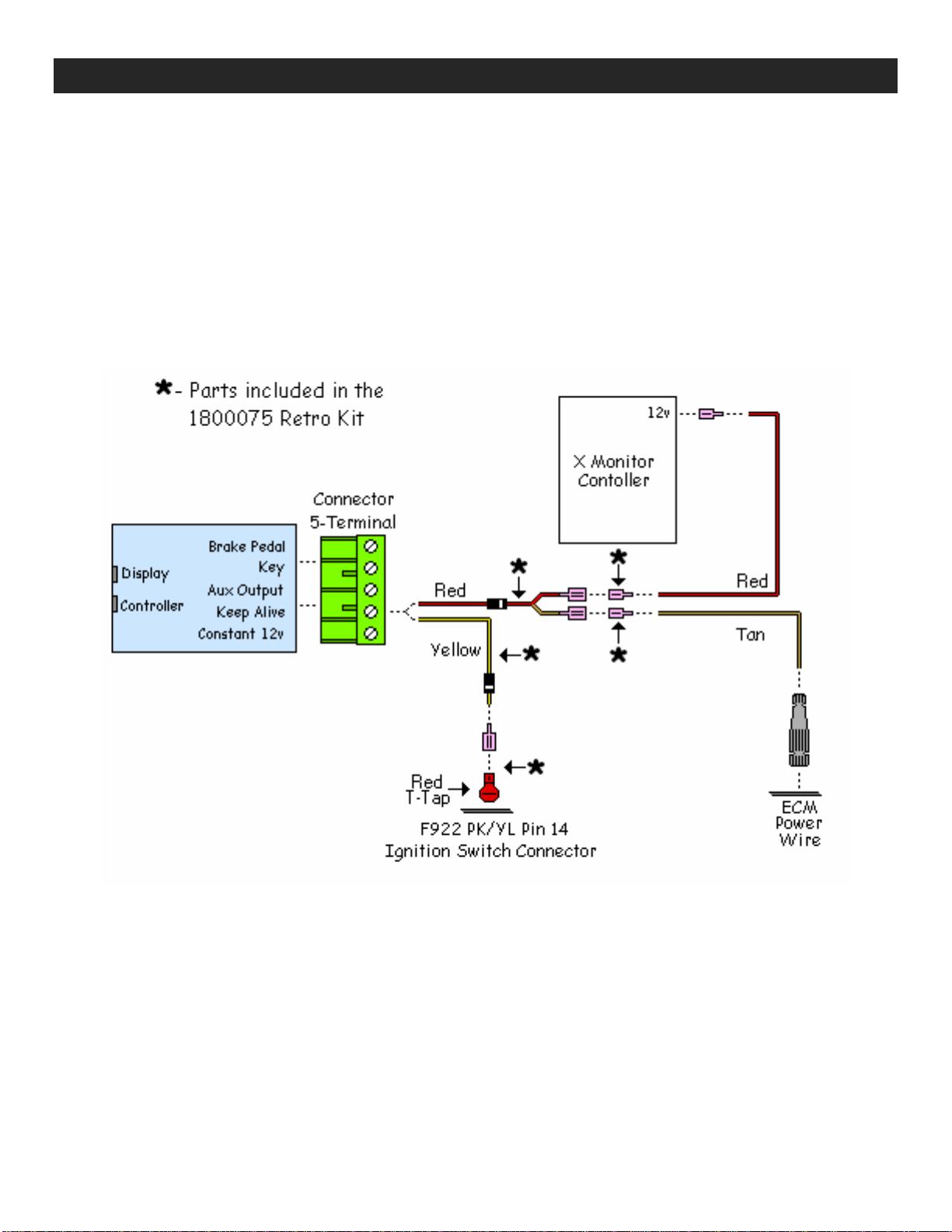
Wastegate Solenoid Power Harness (2004½-05 Dodges Only)
2004½-05 Dodge trucks have a wastegate solenoid that requires power when the CES
keeps the ECM alive in cool down mode. You may notice that the check engine light
comes on (with codes P0480 & P0243) approximately 30 seconds after the key is
turned off. To avoid this requires some extra wiring with diodes to prevent back feeding
power.
The codes being sent do not affect performance or drivability in any way but only
causes the annoyance of the engine light coming on. See the diagram below for
reference.

5/11/2006 1081100 Cool Engine Shutdown Page 13
BD Engine Brake Inc.
Plant Address: Unit A10, 33733 King Rd, Abbotsford, BC, Canada V2S 7M9
U.S. Shipping Address: 88-446 Harrison St, Sumas, WA 98295 U.S. Mailing Address: P.O. Box 231, Sumas, WA 98295
Phone: 604-853-6096 Fax: 604-853-8749 Internet: www.bd-power.com
Temperature Adjustments
The shutdown temperature can be set by using a small flat-head screw driver to adjust
the potentiometer that can be accessed through the hole on top of the CES module
with the markings “550”, “400” and “250”.
By turning the screw clockwise until the potentiometer stops the CES will shutdown at
approximately 550°F; by turning all the way counter clockwise the CES will shutdown
at approximately 250°F. The markings are a general guide as to what the approximate
setting will be; the CES may have to be adjusted a few times until the desired
shutdown temperature is achieved.
Communication / Operation Lights
Through the translucent blue case of the CES module, there will be a Green and Red
LED visible during the operation of the CES. The Green LED will blink when the CES
senses communication between the X Monitor display and module. The Red LED will
light up when the exhaust temperature is above the shutdown temperature setting.
Mounting
Once all the wiring and adjusting has been performed, secure or mount the CES
module so that it is not interfering with feet and moving parts or near direct heat. Some
examples are to use Velcro to mount to the firewall or to the back of the X Monitor
module. Being that the CES module is light, it can be suspended if the wiring is
secure.
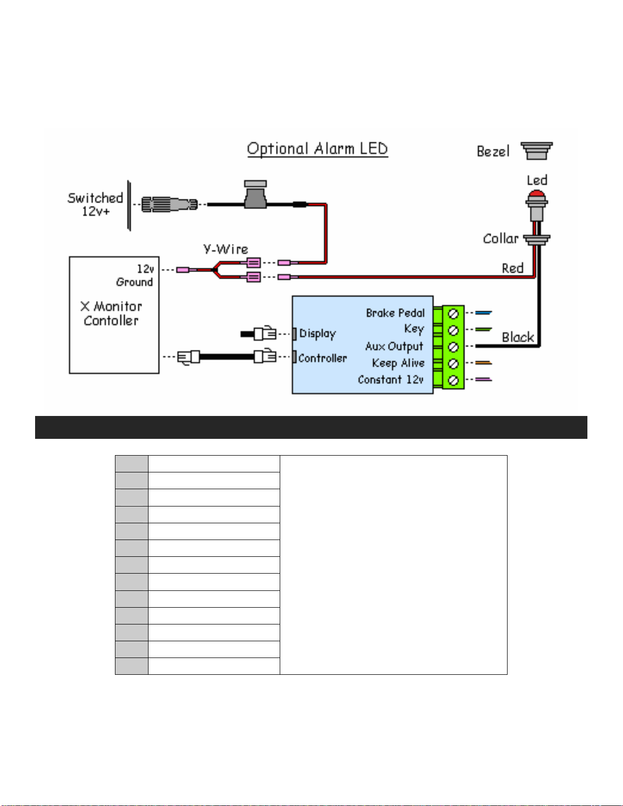
Optional LED Alarm
For those who wish to use an LED for the alarm instead of, or, in conjunction with the
audible alarm, the CES module can control the grounding of a LED through the “Aux
Output” terminal. This terminal could be used to control the grounding of other devices
but is only rated to a maximum of 0.5 amps; exceeding this rating will void the
warranty.
To mount the LED, drill a 0.250” hole in the desired location. From the front, push the
bezel into the hole you just drilled. From the backside, push the LED into the bezel
until it clicks into place, the flange at the base of the LED will be inside the bezel and
the LED will protrude by about 1/8” out the front of the bezel. Push the collar up the
wires and over the bezel/LED until it securely clicks into place.
Run the wires down to the CES and X Monitor modules keeping them from interfering
with moving or heated parts. With the black wire trim any excess, strip the end and
5/11/2006 1081100 Cool Engine Shutdown Page 14
BD Engine Brake Inc.
Plant Address: Unit A10, 33733 King Rd, Abbotsford, BC, Canada V2S 7M9
U.S. Shipping Address: 88-446 Harrison St, Sumas, WA 98295 U.S. Mailing Address: P.O. Box 231, Sumas, WA 98295
Phone: 604-853-6096 Fax: 604-853-8749 Internet: www.bd-power.com
insert into the “Aux Output” terminal on the CES module. With the Red wire trim any
excess, strip the end and attach a blade connector. On the X Monitor module,
disconnect the power lead and replace with Y-wire connected. Connect the LED’s Red
wire to the Y-Wire.
Wire Color Glossary
BK Black
BR Brown
DB Dark Blue
GN Green
GY Gray
LB Light Blue
LG Light Green
OR Orange
PK Pink
RD Red
TN Tan/Light Brown
WT White
YL Yellow
In the wiring diagrams, there are
usually two wire colors for each
OEM wire, for example: RD/LB.
This means it’s a red colored wire
with a light blue tracer.

5/11/2006 1081100 Cool Engine Shutdown Page 15
BD Engine Brake Inc.
Plant Address: Unit A10, 33733 King Rd, Abbotsford, BC, Canada V2S 7M9
U.S. Shipping Address: 88-446 Harrison St, Sumas, WA 98295 U.S. Mailing Address: P.O. Box 231, Sumas, WA 98295
Phone: 604-853-6096 Fax: 604-853-8749 Internet: www.bd-power.com
Questions?
If you have any technical issues, problems or questions with this product, then please
phone our Technical Support Hotline at (800) 887-5030, Monday to Friday, between
8:30am-5:00pm Pacific Standard Time (PST). As an alternative, you can also post a
question or comment on our e-support forum, located at http://www.bd-
power.com/forum/ .

5/11/2006 1081100 Cool Engine Shutdown Page 16
BD Engine Brake Inc.
Plant Address: Unit A10, 33733 King Rd, Abbotsford, BC, Canada V2S 7M9
U.S. Shipping Address: 88-446 Harrison St, Sumas, WA 98295 U.S. Mailing Address: P.O. Box 231, Sumas, WA 98295
Phone: 604-853-6096 Fax: 604-853-8749 Internet: www.bd-power.com
BD ENGINE BRAKE, INC.
LIMITED WARRANTY STATEMENT
THE INSTALLATION OF THIS PRODUCT INDICATES THAT THE BUYER HAS READ AND
UNDERSTANDS THIS AGREEMENT AND ACCEPTS ITS TERMS AND CONDITIONS.
DISCLAIMER OF LIABILITY
BD Engine Brake Inc., its successors, distributors, jobbers, and dealers (hereafter “BD”) shall in no way be responsible
for the product's proper use and service. THE BUYER HEREBY WAIVES ALL LIABILITY CLAIMS.
BD disclaims any warranty and expressly disclaims any liability for personal injury or damages. BD also disclaims any
liability for incidental or consequential damages including, but not limited to, repair labor, rental vehicles, hotel costs, or
any other inconvenience costs by reason of use or sale of any such equipment. The BUYER acknowledges and agrees
that the disclaimer of any liability for personal injury is a material term for this agreement and the BUYER agrees to
indemnify BD and to hold BD harmless from any claim related to the item of any equipment purchased.
This warranty shall not apply to any unit that has been improperly stored or installed, or to misapplication, improper
operation conditions, accidents, neglect, or which has been improperly repaired or altered or otherwise mistreated by the
BUYER or his agent. BD also assumes no liability regarding the improper installation or misapplication of its products. It
is the installer's responsibility to check for proper installation and if in doubt, contact the manufacturer.
LIMITATION OF WARRANTY
BD Engine Brake Inc. (hereafter "BD") warrants to the BUYER that any parts purchased shall be free from defects in
material workmanship. A defect is defined as a condition within the product that would render the product inoperable. BD
gives Limited Warranty as to description, quality, merchantability, fitness for any product’s purpose, productiveness, or
any other matter of BD's product sold herewith. BD shall be in no way responsible for the product’s open use and service
and the BUYER hereby waives all rights other than those expressly written herein. This Warranty shall not be extended or
varied except by a written instrument signed by BD and the BUYER.
The Warranty is Limited to one (1) year from the date of sale and labor costs incurred by the removal and replacement of
the BD product, while performing warranty work, will be covered for 1 (one) year, payable at BD rates, at authorized
centers and with prior approval. Until BD has approved the claim, the consumer may be responsible for these costs.
A Return Authorization (WA) number, obtained in advance from BD, must accompany all products returned for warranty
consideration. All products must be returned, shipping prepaid, to BD and must be accompanied by a dated proof of
purchase receipt. All Warranty claims are subject to approval by BD and repaired or replaced product will be returned to
the customer freight collect. Accepted warranty units, which have been replaced, become the sole property of BD.
This warranty is in lieu of all other warranties or guaranties, either expressed or implied, and shall not extend to any
consumer or to any person other than the original purchaser residing within the boundaries of the continental U.S. or
Canada.
IN THE EVENT THAT THE BUYER DOES NOT AGREE WITH THIS AGREEMENT, THE BUYER MAY PROMPTLY
RETURN THIS PRODUCT, IN A NEW AND UNUSED CONDITION, WITH A DATED PROOF OF PURCHASE, TO THE
PLACE OF PURCHASE WITHIN THIRTY (30) DAYS FROM DATE OF PURCHASE FOR A FULL REFUND.
This manual suits for next models
1
Table of contents
Other BD Diesel Performance Automobile Accessories manuals


Popular Automobile Accessories manuals by other brands


Dunlop
Dunlop L.AMA.10.C.L installation manual

Cruz
Cruz Evo Rack A44-158 Assembly instructions

Kuda-Phonebase
Kuda-Phonebase 1055 Installation instruction

Circontrol
Circontrol eHome Series Instruction & installation manual

GEV
GEV 56 Assembly instructions

Blue Sky Network
Blue Sky Network SKYLINK Frequently asked questions


