2
Table of Contents
Initial Information ........................................................................................................................................ 4
Legal isclaimer ....................................................................................................................................... 4
Planning Guide ......................................................................................................................................... 4
Getting Started ............................................................................................................................................ 5
Power up on the bench ............................................................................................................................ 5
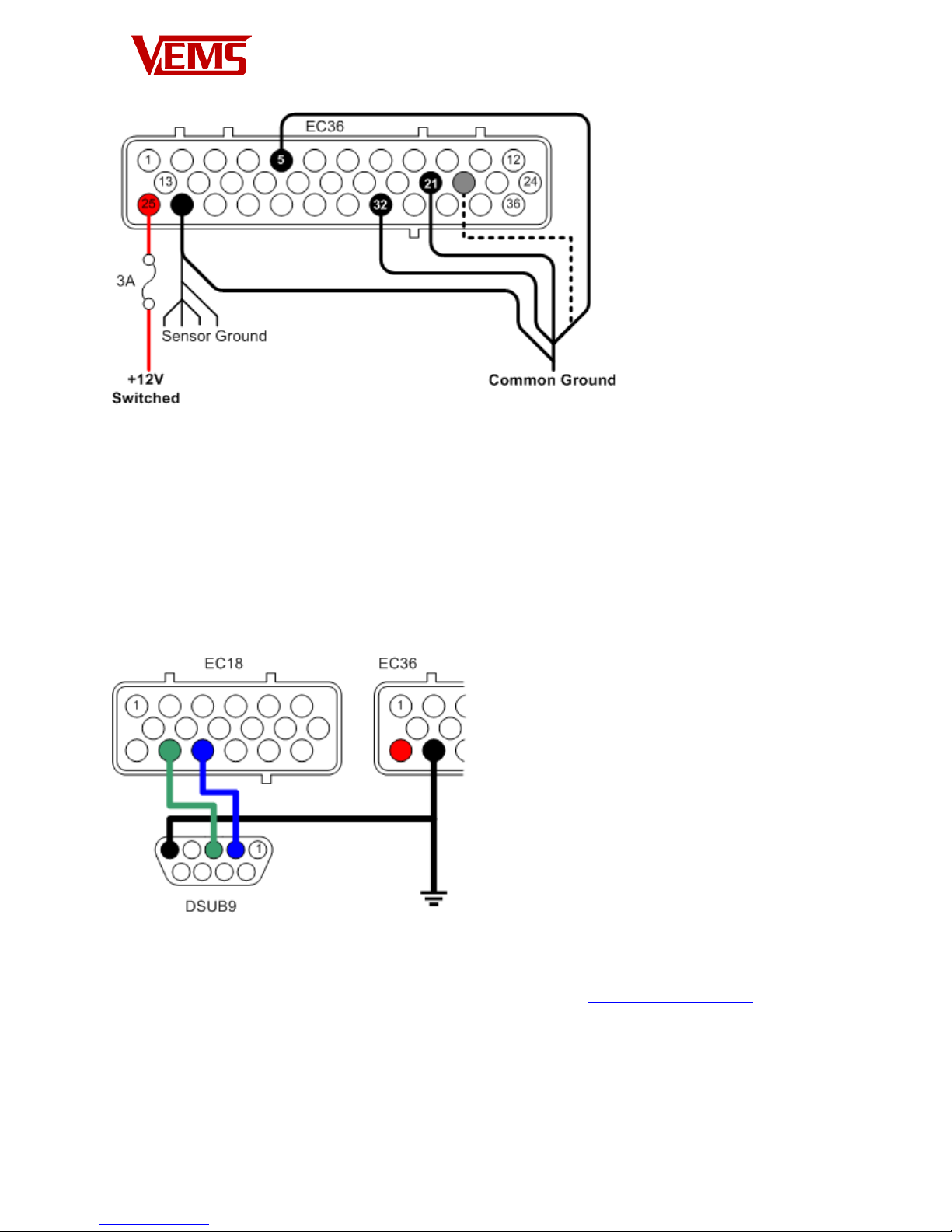
Grounds ................................................................................................................................................... 5
Power Grounds .................................................................................................................................. 5
Sensor Ground ................................................................................................................................... 6
+12V Supply ............................................................................................................................................. 6
Connecting serial port .............................................................................................................................. 7
Connect essential sensors ............................................................................................................................ 8
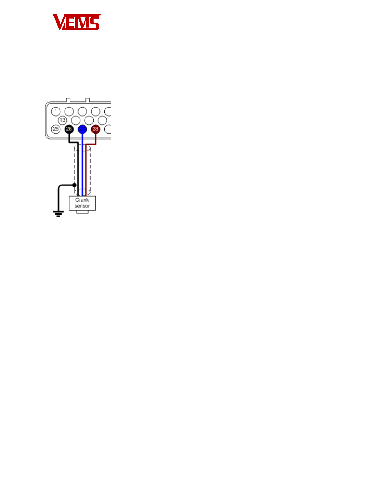
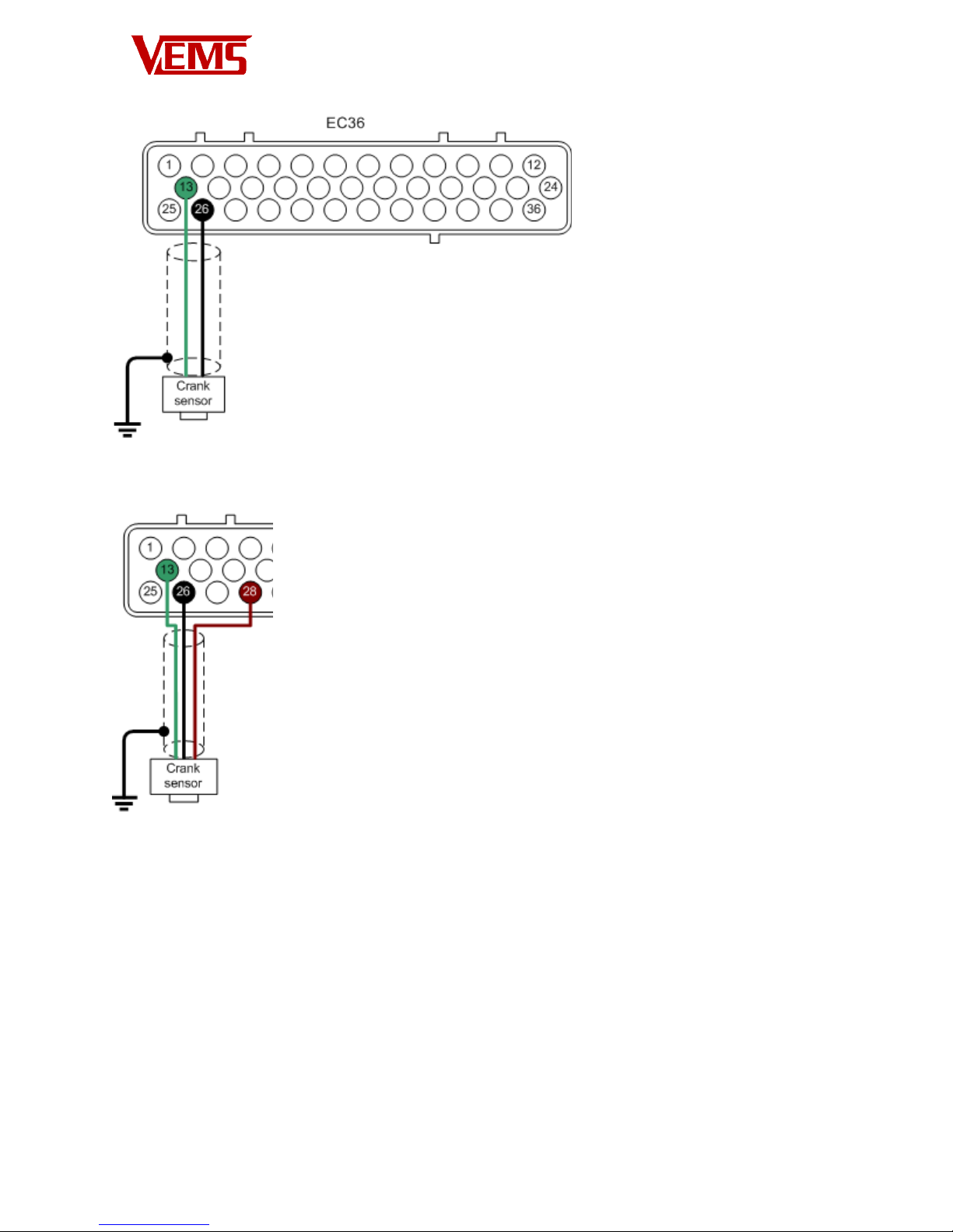
Crank Trigger ............................................................................................................................................ 8
Connecting the primary trigger (Crank) ................................................................................................... 8
Configuring the crank trigger ................................................................................................................... 9
Connecting the Secondary Trigger (Cam) ................................................................................................. 9
Configuring the Secondary Trigger (Cam) .............................................................................................. 10
Temperature Sensors ............................................................................................................................. 10
IAT – Inlet Air Temperature .............................................................................................................. 10
CLT – Coolant Temperature .............................................................................................................. 10
TPS – Throttle Position Sensor ............................................................................................................... 11
Configuring the TPS sensor ................................................................................................................... 11
Secondary Sensors ..................................................................................................................................... 12
WBO2 ..................................................................................................................................................... 12
EGT ........................................................................................................................................................ 12
Knock .................................................................................................................................................... 13
Primary Outputs ........................................................................................................................................ 14
Connecting Ignition Components .......................................................................................................... 14
Example coil connections ................................................................................................................ 16