VENCO VRE 800 x 500–5–G–1–2 Owner's manual

1 / 4
ELECTRIC DUCT HEATER INSTALLATION-OPERATION-MAINTENANCE
1. INTRODUCTION
1. Case; made of galvanized or stainless material, which is optional and also depend on applications,
2. Heating elements; made of stainless material-SST 304,
3. Junction Box; contains the necessary terminals for electrical connections.
The duct connection is suitable for push-in installation in rectangular ducts for VRE models and in round ducts for
VCE models.
The installation of electric duct heaters with control equipments and control-box is optional.
2. OPERATIONAL LIMITS
•Electric duct heaters are designed for a maximum output temperature of 40°C.
•Air velocity must not be less than 1,5m/sn.
•Electric duct heaters can be installed in a horizontal or vertical duct.
•All electric duct heaters can be produced for the power group voltages as 230V-1phase, 400V-2phase, and 400V-
3phase.
•All heaters can be operated in the environmental temperature between minimum -20°C and maximum +40°C.
•Please contact us for the specific applications such as operating the heaters in the environment which causes
corrosion.
3. NOMENCLATURE
VRE 800 x 500 –5 –G –1 –2
VTL 800 x 500 –5 –G –1 –2
3
2
1
Number of stage
Voltage (1: 230V ~, 2: 400V 2~, 3: 400V 3~)
Material of casing (G: Galvanized / S:SST430 / SS:SST316 Stainless Steel)
Output [kW]
Duct height [mm]
Duct Weight [mm]
Code of Rectangular Electric Duct Heater
THE UNIT MUST BE OPERATED APPROPRIATE APPLICATIONS FOR PURPOSES
DESIGN and TECHNICAL SPECIFICATIONS, OTHERWISE THE APPLIER WILL BE
RESPONSIBLE.
BEFORE START-UP, READ THE MANUEL and KEEP IT WITHIN EASY REACH OF
SERVICING PERSONNEL.
THE APPLIER WILL BE RESPONSIBLE FOR DEFECTS OCCURED DUE TO
OPERATING THE UNIT BY NOT AUTHORIZED PERSONNEL OR USING THE SPARE
PARTS NOT ORIGINAL.
1
2
3
Number of stage
Voltage (1: 230V ~, 2: 400V 2~, 3: 400V 3~)
Material of casing (G: Galvanized / S:SST430 / SS:SST316 Stainless Steel)
Output [kW]
AHU Inside height [mm]
AHU Inside Weight [mm]
Code of AHU Type Electric Heater

2 / 4
VCE 160 –5 –G –1 –2
4. TRANSPORTATION –STORAGE –INSTALLATION
Transpalet, forklift or hands can be used for lifting or transporting the heaters. Appropriate lifting methods should be
used in order to minimize any possible damage.
Electric duct heaters have to be kept in a closed area where the heat should be between –20 ºC and + 40 ºC and
relative humidity should not exceed 80%. Also the unit should be kept away from dust, gas, corrosive streams and
effects cause corrosion. The packaging of heaters for storage should be done carefully in order to prevent damages
to duct connections and electrical connections.
Electric duct heaters can be installed in a horizontal or vertical duct system. In a horizontal duct the junction box must
be installed facing upwards or within an angle of rotation of 90° to the sides. Installation with the junction box facing
downwards is not permitted. The duct heater must be installed in such a way that it receives an even flow of air
across its entire area.
5. CONNECTIONS
5.1. DUCT CONNECTIONS
For circular electric duct heaters; the distance to or from a duct elbow, fan, damper and similar must be at least
double the connection diameter. For rectangular electric duct heaters; it must be at least the dimension equivalent to
the diagonal of the duct heater, i.e. from corner to corner in the duct section of the heater.
5.2. ELECTRICAL CONNECTIONS
All electricity connections should be designed and prepared according to EN 60204 –1 Standards. The electrical
materials, cables and all relevant control and remote control equipments should be chosen and designed suitable to
unit peculiarities and requirements. Electrical connections shall be done according to the wiring diagram given in the
junction box.
Electric duct heaters must always be installed so that they are interlocked either against the fan that blows air
through the heater or against the airflow that passes the heater.
6. SAFETY
6.1. WARNING and ADVICE
This user manual is prepared to provide correct usage and assembling of the heaters and warn the maintenance
personnel for the possible dangers.
Possible dangers related to heaters are as follow;
Number of stage
Voltage (1: 230V ~, 2: 400V 2~, 3: 400V 3~)
Material of casing (G: Galvanized / S:SST430 / SS:SST316 Stainless Steel)
Output Power [kW]
Duct diameter [mm]
Code of Circular Electric Duct Heater
DUCT CONNECTIONS SHALL BU DONE ACCORDING TO THE DIRECTION OF AIR
FLOW LABEL WHICH IS PLACED ONTO THE HEATER.
ELECTRICAL CONNECTIONS SHALL BE DONE ACCORDING TO EN 60204-1
STANDARD BY TRAINED and AUTHORIZED PERSONNEL.
THE POWER SUPPLY TO THE DUCT HEATER MUST BE INTERRUPTED IF THE
FAN/AIRFLOW IS STOPPED. OTHERWISE, ELECTRICAL DUCT HEATER WILL BE
TROUBLE, BECAUSE THE AIRFLOW DOES NOT PASS THROUGH THE HEATER.

3 / 4
•Never expose the heaters to moisture, strokes and external effects.
•The heaters should not be used in the environment where corrosion and explosive gasses exist.
•The heaters should be maintained by trained personnel.
•Do not repair or adjust, when the heater is running.
•Turn the electrical switch off, before open the junction box.
•Never expose cables and connections to the water.
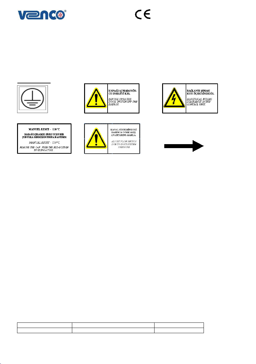
6.2. SAFETY LABELS
Necessary warning labels are placed onto the heaters for the users or service personnel. When the unit is put into the
operation, following stickers have to be controlled whether they are exist or not.
Warning Labels:
Figure 6.2.1. Ground Label Figure 6.2.2. Switch-Off Label Figure 6.2.3. Wiring Diagram
Figure 6.2.4. Manuel Reset Figure 6.2.5. Adjust Flow Switch Label Figure 6.2.6. Direction of Airflow Label
7. CONTROLS BEFORE START-UP
Please make sure, electrical cables, fuse and duct connections are made correctly. There can be some materials
which damage to the case of heater and also heating elements, please make sure inside of the heater is clear. Due
to external effects, the case of heater can be damaged, please check it and if it is necessary, please contact us.
8. SAFETY REQUIREMENTS
VENCO electric duct heaters are produced according to TS 2000 (EN 60335-1) and TS 10316 (EN 60204-1) standards
and EMC 89/336, LVD72/23 numbered European Union Directives and carry the CE signs on themselves. However,
the unit can be dangerous if the unit is not used or the service is not given by trained and experienced personnel, and
indicated security precautions are not followed.
8.1. WARNINGS BEFORE START-UP
•VRE-Rectangular and VCE-circular electric duct heaters are designed for operating temperature of out-going air up
to 40°C and also for getting an indoor air quality. The applier will be responsible for operating the heaters for other
purposes.
•Standard heaters can not be used for heating explosive and combustible gasses. Please contact us, if you require
non-standard heaters.
•Operating and installation shall be done according to the national standards of the country where the heater will be
used. The user will be responsible for the application of requirements in the national standards.
•It is forbidden to make any change on the heaters by the user or the authorized personnel. Damages, which are
occurred as a result of that kind of changes, are not under warranty. The heater shall be operated by the
authorized personnel and by applying the necessary safety requirements.
•The requirements in the Manuel shall be consider preventing the hazards which may be occurred when operating
of the heater. Safety tools shall not be taken out by the user or the authorized personnel. If it is necessary for
maintenance, safety tools shall be fitted and checked after the maintenance procedure.
Electricity shall be switched off, during the maintenance applications.
General Hazards
TYPE of HAZARD
ORIGIN of HAZARD
HAZARD
Electrical contact
Electric cables, electrical parts
Very High Dangerous

4 / 4
9. START-UP and OPERATING
Requirements in the Manuel shall be considered before starting up of the heaters or after the maintenance. Electrical
connections shall be done according to the standards. Duct connections shall be done according to the requirements
of the Manuel and shall be checked the design according to the acceptable engineering applications. If exist, flow
switch adjustment shall be done according to 1.5m/s duct system air flow.
If any problem is occurred, electricity shall be switched-off. Then, the reason of problem shall be checked and if it is
necessary, please contact us. After switch off electric heater, airflow must continue at least two minutes.
10. MAINTENANCE
The power supply to the duct heater must be interrupted and airflow must continue at least two minutes, after
stopping fan you must to wait to stop fan blades before the maintenance periods. Electrical connections; The
Ampere shall be measured to prevent risks once a year, which are the leakage and the overloading of electricity.
Casing; The housing shall be checked to prevent risks once a year, which are the corrosion, external effects.
Heating Elements; Resistances shall be cleaned by using a vacuum cleaner or wired-brush at least once a year,
which will remove dust and foreign objects on the surface of heat elements.
11. TROUBLESHOOTING and REMEDIES
When abnormality is generated, the power supply to the duct heater must be interrupted and airflow must continue at
least two minutes. After the cause abnormality is removed, operate equipment and check proper functioning.
Necessary measurements must be taken care, which are given below.
•Casing is bashed or not.
•Heating elements are bashed or not.
•No leakage in the duct systems and also casing.
•The details of the duct connections are checked,
•The measured airflow rate, ampere, the out-side temperature e.t.c.
•The technical specifications, which are given on the type label placed onto the heater, must be checked.
12. WARRANTY CONDITIONS
Warranty period starts at invoice date and it is for (2) years.
•Failures, due to wrong assembly in spite of the requirements of manuel,
•Doing wrong electricity connections, doing a connection apart from what is indicated electricity scheme label,
•Failures, due to electrical problems as a result of power supply system,
are not covered by warranty.
For customer needs, please contact us as given below:
DURING THE OPERATION NEVER CHECK OR CLEAN THE HEATERS. IT MAY
CAUSE ELECTRIC SHOCK AND IT IS VERY DANGEROUS TO TOUCH THE
ELECTRICAL PART. BE SURE TO TURN OFF THE OPERATION SWITCH AND
DISCONNECT THE POWER AND WAIT FOR COOLING OF THE HEATING
ELEMENTS.
THE HEATER HAS A BUILT-IN OVERHEATING PROTECTION AT THE
TEMPERATURE OF 70°C, WHICH IS AUTOMATIC RESETTING.
WHEN ABNORMALITY IS GENERATED, PLEASE CONTACT US.
THE HEATER HAS A BUILT-IN OVERHEATING PROTECTION AT THE
TEMPERATURE OF 110°C, WHICH IS MANUEL RESETTING. FIRSTLY, THE CAUSE
OF AUTOMATIC RESETTING SHALL BE REMOVED. DISCONNECT THE POWER AND
THEN REMOVE THE CAP, PUSH THE RED-BUTTON BY A TOOL TO RESET
MANUALLY. FINALLY, CONNECT THE POWER AND OPERATED THE HEATER
AGAIN.
VENCO A.S.
2004 Sokak No:5
TOSB
Turgutlu (45400)
MANISA –TURKEY
Tel : +90 236 332 5070
Fax : +90 236 332 5030
Web : www.venco.com.tr
E-mail : venco@venco.com.tr
This manual suits for next models
2
Table of contents
Popular Heater manuals by other brands

L.B. White
L.B. White Tradesman K70 owner's manual

Toyotomi
Toyotomi zibro LC-400 operating manual

Archgard
Archgard Optima 70-2 User's installation, operation and maintenance manual

UNIPRODO
UNIPRODO UNI SAUNA V6.0KW user manual

Siemens
Siemens 2NC8 2F Series Instructions for installation and operation

Anslut
Anslut 017414 operating instructions