Desa RCLP50B User manual

CANADIAN PROPANE
CONSTRUCTION
HEATER
OWNER’SMANUAL
!
GENERAL HAZARD WARNING:
FAILURETOCOMPLYWITHTHEPRECAUTIONSANDINSTRUC-
TIONSPROVIDEDWITHTHISHEATER,CANRESULTINDEATH,
SERIOUS BODILY INJURY AND PROPERTY LOSS OR DAMAGE
FROMHAZARDSOFFIRE,EXPLOSION,BURN,ASPHYXIATION,
CARBON MONOXIDE POISONING, AND/OR ELECTRICAL
SHOCK.
ONLY PERSONS WHO CAN UNDERSTAND AND FOLLOW THE
INSTRUCTIONS SHOULD USE OR SERVICE THIS HEATER.
IF YOU NEED ASSISTANCE OR HEATER INFORMATION SUCH
ASANINSTRUCTIONSMANUAL,LABELS,ETC.CONTACTTHE
MANUFACTURER.
Model RCLP50B
IMPORTANT
Readandunderstandthismanual before assembling, starting, or servicing heater.
Improper use of heater can cause serious injury. Keep this manual for future
reference.

2
103911
Safety Information......................................................................... 2
Product Identification ....................................................................4
Unpacking......................................................................................4
Theory of Operation ......................................................................5
Propane Supply..............................................................................5
Installation .....................................................................................6
Ventilation .....................................................................................7
Operation .......................................................................................7
Storage ........................................................................................... 9
Maintenance ..................................................................................9
Troubleshooting.............................................................................10
Service Procedures ........................................................................11
Specifications................................................................................. 14
Wiring Diagram............................................................................. 14
Accessories ....................................................................................15
Technical Service ..........................................................................15
Replacement Parts .........................................................................15
Illustrated Parts List.......................................................................16
Warranty and Repair Service.........................................................Back Cover
SECTION PAGE
CONTENTS
SAFETY
INFORMATION
Safety Information continues on next page
WARNING ICON G 001
WARNING: FIRE, BURN, INHALATION, AND EXPLOSION
HAZARD.KEEPSOLIDCOMBUSTIBLES,SUCHASBUILDING
MATERIALS, PAPER OR CARDBOARD, A SAFE DISTANCE
AWAY FROM THE HEATER AS RECOMMENDED BY THE
INSTRUCTIONS. NEVER USE THE HEATER IN SPACES
WHICH DO OR MAY CONTAIN VOLATILE OR AIRBORNE
COMBUSTIBLES,ORPRODUCTSSUCHASGASOLINE,SOL-
VENTS, PAINT THINNER, DUST PARTICLES OR UNKNOWN
CHEMICALS.
WARNING ICON G 001
WARNING
NOT FOR HOME OR RECREATIONAL VEHICLE USE.
The heater is designed for use as a construction heater in accordance with ANSI
Z83.7•CGA2.14.Otherstandardsgoverntheuseoffuelgasesandheatingproducts
for specific uses. Your local authority can advise you about these. The primary
purposeof constructionheatersistoprovidetemporaryheating ofbuildings under
construction,alterationorrepair. Properlyused,theheaterprovidessafeeconomi-
cal heating. Products of combustion are vented into the area being heated.
Wecannot foreseeevery usewhich maybe madeof ourheaters.Checkwithyour
local fire safety authority if you have questions about heater use.
Other standards govern the use of fuel gases and heat producing products for
specific uses. Your local authorities can advise you about these.
Carbon Monoxide Poisoning: Some people are more affected by carbon
monoxidethanothers.Earlysignsofcarbonmonoxidepoisoningresembletheflu,
with headaches, dizziness, and/or nausea. If you have these signs, the heater may
not be working properly. Get fresh air at once! Check for proper ventilation and
have heater serviced.
WARNING ICON G 001
WARNINGS

3
103911
2
SAFETY
INFORMATION
Continued
!
WARNINGS
Continued
PropaneGas:Propanegasisodorless.Anodor-makingagentisaddedtopropane
gas. The odor helps you detect a propane gas leak. However, the odor added to
propane gas may fade. Propane gas may be present even though no odor exists.
Makecertainyoureadandunderstandallwarnings.Keepthismanualforreference.
It is your guide to safe and proper operation of this heater.
•Install and use heater with care. Follow all local ordinances and codes. In the
absence of local ordinances and codes, refer to the Standard for Storage and
Handling of Liquefied Petroleum Gas, ANSI/NFPA 58 and the Natural Gas
Installation Code, CAN/CGA B149.2. This instructs on the safe storage and
handling of propane gases.
•Use only the electrical voltage and frequency specified on model plate.
•The electrical connections and grounding of the heater shall follow the Na-
tional Electric Code, ANSI/NFPA 70, or Canadian Electrical Code, Part 1.
•Electrical grounding instructions —This appliance is equipped with a three-
prong (grounding) plug for your protection against shock hazard and should
be plugged directly into a properly grounded three-prong receptacle.
•Use only a three-prong, grounded extension cord.
•Use only the hose and factory preset regulator provided with the heater.
•Use only propane gas set up for vapor withdrawal.
•Provide adequate ventilation. Before using heater, provide at least a 1.5 square
foot (0.14 square meters) opening of fresh, outside air. This heater produces
carbonmonoxide,whichislistedbytheStateofCaliforniaasareproductivetoxin
under Proposition 65.
•For indoor use only. Do not use heater outdoors.
•Do not use heater in occupied dwellings or in living or sleeping quarters.
•Do not use heater below ground level. Propane gas is heavier than air. If a leak
occurs, propane gas will sink to the lowest possible level.
•Keep appliance area clear and free from combustible materials, gasoline, paint
thinner, and other flammable vapors and liquids. Do not use heater in areas
with high dust content.
•Minimum heater clearances from combustibles:
Outlet: 6 Ft.(1.8 m) Sides: 2 Ft.(60 cm) Top: 6 Ft.(1.8 m) Rear: 2 Ft.(60 cm)
•Keep heater at least six feet from propane tank(s). Do not point heater at
propane tank(s) within 20 feet (6 m).
•Keep propane tank(s) below 100°F (38°C).
•Check heater for damage before each use. Do not use a damaged heater.
•Check hose before each use of heater. If highly worn or cut, replace before
using heater.
•Locate heater on stable and level surface if heater is hot or operating.
•Not intended for use on finished floors.
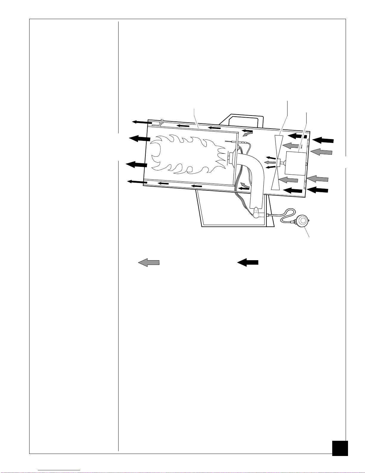
•Never block air inlet (rear) or air outlet (front) of heater.
•Keep heater away from strong drafts, water spray, rain, or dripping water.
•Do not leave heater unattended.
•Keep children and animals away from heater.
•Never move, handle, or service a hot, operating, or plugged-in heater. Severe
burns may result. Wait 20 minutes after turning heater off.
•To prevent injury, wear gloves when handling heater.
•Never attach duct work to heater.
•Do not alter heater. Keep heater in its original state.
•Do not use heater if altered.
•Turn off propane supply and unplug heater when not in use.
•Use only original replacement parts. This heater must use design-specific
parts. Do not substitute or use generic parts. Improper replacement parts could
cause serious or fatal injuries.

4
103911
PRODUCT
IDENTIFICATION
Figure 1 - 50,000 BTU/Hr Model
Power
Cord
Hose /Regulator
Assembly
Inlet
Connector
Handle
Shell
Hot Air Outlet
(Front)
Fan Guard
Piezo Ignitor
Button
Automatic
Control Valve
Button
UNPACKING 1. Remove all packing items applied to heater for shipment. Keep plastic cover
caps (attached to inlet connector and hose/regulator assembly) for storage.
2. Remove all items from carton.
3. Check all items for shipping damage. If heater is damaged, promptly inform
dealer where you bought heater.
Motor
Heater Base

5
103911
Air For Combustion Air For Heating
THEORY OF
OPERATION
Combustion
Chamber
Clean
Heated
Air Out
(Front)
Hose/Regulator
Assembly
Cool Air In
(Back)
The Fuel System: The hose/regulator assembly attaches to the propane gas
supply. This provides fuel to the heater.
The Air System: The motor turns the fan. The fan pushes air into and around
the combustion chamber. This air is heated and provides a stream of clean, hot air.
The Ignition System: The piezo ignitor lights the burner.
The Automatic Control System: This system causes the heater to shut down
if the flame goes out.
Motor
Fan
Figure 2 - Cross Section Operational View
PROPANE
SUPPLY
Propane gas and propane tank(s) are to be furnished by the user.
Use this heater only with a propane vapor withdrawal supply system. See Chapter 5
of the Standard for Storage and Handling of Liquefied Petroleum Gas, ANSI/NFPA
58 and or CAN/CGA B149.2. Your local library or fire department will have this
booklet.
The amount of propane gas ready for use from propane tanks varies. Two factors
decide this amount:
1. The amount of propane gas in tank(s)
2. The temperature of tank(s)
This heater is designed to operate with a minimum 20-pound (9 kg) propane tank.
You may need two or more tanks or one larger tank in colder weather. Use a 100-
pound (45 kg) tank for longer operation or in very cold weather. Less gas is
vaporized at lower temperatures. Your local propane gas dealer will help you select
the proper supply system. The minimum surrounding air temperature rating for
each heater is -20°F (-29°C).
Average Temperature °F (°C)
At Tank Location 40(4.4) 32(0) 20(6.7) 10(-12) 0(-18) -10(-23) -20(-29)
Number Of Tanks
(100-pound/45 kg) 11111 2 2

6
103911
INSTALLATION
Inlet Connector Hose
Figure 4 - Hose and Inlet Connector
!
WARNING
Review and understand the warnings in the Safety Informa-
tion Section, pages 2 and 3. They are needed to safely
operate this heater. Follow all local codes when using this
heater.
3. Connect hose to inlet connector. Tighten firmly using a wrench.
IMPORTANT:
Use extra hose or piping if needed. Install extra hose or piping
between hose/regulator assembly and propane tank. You must use the regula-
tor supplied with heater.
Propane
Tank
Propane
Supply
Valve Regulator
Hose
POL Fitting
Figure 3 - Regulator Position
1. Provide propane supply system (see Propane Supply, page 5).
2. Connect POL fitting on hose/regulator assembly to propane tank(s). Turn POL
fitting counterclockwise into threads on tank. Tighten firmly using
wrench.
IMPORTANT:
Position regulator so that hose leaving the regulator is
in a horizontal position (see Figure 3). This places the regulator vent in the
proper position to protect it from the weather.
!
WARNING
Test all gas piping and connections for leaks after installa-
tion or servicing. Never use an open flame to check for a
leak. Apply a mixture of liquid soap and water to all joints.
Bubbles forming show a leak. Correct all leaks at once.

7
103911
4. Open propane supply valve on propane tank(s) slowly.
Note:
If not opened
slowly, excess-flow check valve on propane tank may stop gas flow. If this
happens, close propane supply valve and open again slowly.
5. Check all connections for leaks. Apply mixture of liquid soap and water to gas
joints. Bubbles forming show a leak that must be corrected.
VENTILATION
OPERATION
Continued
!
WARNING
Review and understand the warnings in the Safety Informa-
tion section, pages 2 and 3. They are needed to safely
operate this heater. Follow all local codes when using this
heater.
!
WARNING
Provide at least a 1.5 square foot (0.14 square meters) open-
ing of fresh, outside air while running heater. If proper fresh,
outside air ventilation is not provided, carbon monoxide
poisoning can occur. Provide proper fresh, outside air
ventilation before running heater.
!
WARNING
Never use an open flame to check for a leak. Apply a mix-
ture of liquid soap and water to all joints. Bubbles forming
show a leak that must be corrected. Correct all leaks at
once.
4. Plug extension cord into a 120 volt/60 hertz, 3-hole, grounded outlet. Motor
will start. Fan will turn, forcing air out front of heater.
To Start Heater
1. Follow all installation, ventilation, and safety information.
2. Locate heater on stable and level surface. Make sure strong drafts do not blow
into front or rear of heater.
3. Plug power cord of heater into a three-prong, grounded extension cord.
Extension cord must be at least six feet long. Extension cord must be UL/
CSA listed.
Extension Cord Wire Size Requirements
Up to 50 feet (15 m)long, use 18 AWG rated cord.
51 to 100 feet (16 to 30 m) long, use 16 AWG rated cord.
101 to 200 feet (31 to 60 m) long, use 14 AWG rated cord.
6. Close propane supply valve.

8
103911
5. Open propane supply valve on propane tank(s) slowly.
Note:
If not opened
slowly, excess-flow check valve on propane tank may stop gas flow. If this
happens, close propane supply valve and open again slowly.
OPERATION
Continued
!
WARNING
Be sure motor and fan are running before pushing in auto-
matic control valve button. Flames could flash outside
heater if motor and fan are not running.
To Stop Heater
1. Tightly close propane supply valve on propane tank(s). Allow heater to burn
remaining fuel in hose.
2. Wait a few seconds. Heater will burn gas left in supply hose.
3. Unplug heater.
To Restart Heater
1. Wait five minutes after stopping heater.
2. Repeat steps under To Start Heater, page 7.
6. Push in and hold automatic control valve button (see Figure 5). Push piezo
ignitor button (see Figure 5). You may need to push piezo ignitor button 3-8
times until the burner lights. When burner lights, keep automatic control valve
button pushed in. Release button after 30 seconds.
Note:
If heater fails to ignite, hose may have air in it. If so, keep automatic
control valve button pressed and wait 20 seconds. Release automatic control
valve button and wait 20 seconds for unburned fuel to exit heater. Repeat step
6.
Piezo Ignitor
Button
Automatic Control
Valve Button
Figure 5 - Automatic Control Valve Button and Piezo Ignitor Button

9
103911
STORAGE
1. Store propane tank(s) in safe manner. See Chapter 5 of Standard for Storage
and Handling of Liquefied Petroleum Gases, ANSI/NFPA 58 and/or CAN/CGA
B149.2. Follow all local codes. Always store propane tanks outdoors.
2. Place plastic cover caps over brass fittings on inlet connector and hose/regula-
tor assembly.
3. Store in dry, clean, and safe place. Do not store hose/regulator assembly inside
heater combustion chamber.
4. When taking heater out of storage, always check inside of heater. Insects and
small animals may place foreign objects in heater. Remove motor and other
internal parts if needed to remove foreign objects (see Service Procedures,
page 11).
MAINTENANCE
!
CAUTION
Disconnect heater from propane supply tank(s).
!
WARNINGS
•Never service heater while it is plugged in, connected
to propane supply, operating, or hot. Severe burns and
electrical shock can occur.
•Keep heater clear and free from combustible materials,
gasoline, and other flammable vapors and liquids.
•Do not block the flow of combustion or ventilation air.
1. Keep heater clean. Clean heater annually or as needed to remove dust and
debris. If heater is dirty or dusty, clean heater with a damp cloth. Use house-
hold cleaners on difficult spots.
2. Inspect heater before each use. Check connections for leaks. Apply mixture of
liquid soap and water to connections. Bubbles forming show a leak. Correct all
leaks at once.
3. Inspect hose/regulator assembly before each use. If hose is highly worn or cut,
replace.
4. Have heater inspected yearly by a qualified service agency.
5. Keep inside of heater free from combustible and foreign objects. Remove
motor and other internal parts if needed to clean inside of heater (see Service
Procedures, page 11).
6. Clean fan blades each season or as needed (see Fan, page 12).

10
103911
TROUBLE-
SHOOTING
Checkvoltagetoelectricalout-
let. If voltage is good, check
heater power cord for breaks.
Adjustmotor/fanguardtokeep
fanfromhittinginsideofheater
shell. Bend fan guard if neces-
sary.
Replace fan. See Fan, page 12.
Replace motor. See Motor,
page 11.
Repeat installation and opera-
tion instructions. See Installa-
tion, page 6 and Operation,
page 7.
A)Check ignitorwire.Tighten
or reattach loose ignitor wire.
SeeFigure13,page13forigni-
tor wire location.
B) Set gap between ignitor
electrode and target plate to
.17" (4.3 mm).
C) Tighten nut holding piezo
ignitor to base of heater.
D) Replace ignitor electrode.
See Ignitor, page 13.
This can happen when running
heater in temperatures above
85°F (29°C). Run heater in
cooler temperatures.
Check heater inlet and outlet.
Remove any obstructions.
Replace fan. See Fan, page 12.
Clean heater. See Mainte-
nance, page 9.
!
WARNING
Use only in areas free of
high dust content.
No electrical power
to heater
Fan hitting inside of
heater shell
Fan blades bent
Defective motor
Userdidnotfollowinstal-
lation or operation in-
structions properly
No spark at ignitor. To
test for spark, follow step
9 under Ignitor, page 13.
If you see spark at ignitor,
have heater serviced by
qualified service person.
If no spark seen:
A) Loose or disconnected
ignitor wire
B) Wrong spark gap
C) Piezo ignitor loose
D) Bad ignitor electrode
Highsurroundingairtem-
perature causing thermal
limit device to shut down
heater.
Restricted air flow
Damaged fan
Excessive dust or debris
in surrounding area
Fan does not turn
when heater is
plugged in.
Heater will not
ignite.
Heater shuts down
while running.
OBSERVED FAULT POSSIBLE CAUSE REMEDY
!
WARNING
Never service heater while it is plugged in, connected to
propane supply, operating, or hot. Severe burns and
electrical shock can occur.

11
103911
SERVICE
PROCEDURES
Motor
1. Access ground screw
through underside of
heater base. Remove
ground screw. Disconnect
the green motor wire and
the green power cord wire
from underside of shell
(see Figure 6).
2. Remove black and white
motor wires from terminal
board (see Figure 6).
3. Remove two wire guard
screws. Remove wire
guard.
4. Set heater on its base.
Remove three screws that
attach fan guard to heater
shell (see Figure 7).
5. Remove motor and fan
guard from heater shell.
Carefully pull the green,
black, and white motor
wires from hole in shell
(see Figure 7).
6. Use pliers to remove the
fan nut from front of
motor shaft (see Figure 8).
7. Remove fan. Be careful
not to damage the fan
blade pitch.
8. Use nut driver to remove
three nuts that attach fan
guard to motor.
Remove
fan guard from motor (see
Figure 9).
9. Discard old motor.
!
WARNING
Never service heater while it is plugged in, connected to
propane supply, operating, or hot. Severe burns and elec-
trical shock can occur.
Figure 9 - Removing or Attaching
Fan Guard from Motor
Motor Wires
Figure 8 - Removing Fan Nut from
Motor Shaft
Fan
Nut
Figure 7 - Removing Motor and Fan Guard from Heater
Ground Screw
Wire Guard Screws
Wire Guard
Continued
Underside of Heater Base
Hole in Shell
for Wires
Figure 6 - Location of Ground Screw and Wire Guard
Terminal Board
Fan Guard Screw
Fan Guard

12
103911
10.Attach fan guard to new
motor with three nuts.
Tighten nuts firmly.
11.Place fan onto motor shaft
of new motor.
IMPORTANT:
When
placing fan onto motor
shaft, make sure part
number stamped on fan is
facing motor. Attach fan
nut to end of motor shaft.
Tighten fan nut firmly.
12.Place motor and fan guard
into rear of heater shell.
Carefully route motor wires
through hole in shell (see
Figure 10).
13.Insert three screws through
heater shell and into fan
guard.Tightenscrewsfirmly.
14.
Turn heater on its side to
access opening in bottom of
base. Connect green motor
wire and green power cord
wire to heater shell using
ground nut (see Figure 6,
page 11).
15.Attach black and white
wires to empty connectors
on black and white wire
sides of terminal board.
16.Attach wire guard to shell
with two screws (see Figure
6, page 11).
Motor
(Continued)
Figure 10 - Replacing Motor and Fan Guard into Heater
Hole in Shell
for Motor Wires
Fan
1. Remove fan and motor (see
Motor, page 11, steps 1
through 6.
2a. If replacing fan, remove
old fan and discard. Go to
step 5 below.
2b.If cleaning fan, remove fan.
Be careful not to damage
the fan blade pitch.
3. Clean fan using soft cloth
moistened with kerosene or
solvent.
4. Dry fan thoroughly.
5. To replace fan, follow steps
11 through 16 above.

13
103911
Ignitor
1. Remove motor and fan
guard from heater (see
Motor, page 11, steps 1
through 5).
2. Remove black ignitor wire
from piezo ignitor. Access
ignitor wire through
underside of heater base
(see Figure 11). Push wire
up through bushing in
heater shell.
3. Remove ignitor mounting
screw from rear head
using nut-driver or stan-
dard screwdriver (see
Figure 12).
4. Remove ignitor from rear
head.
5. Install new ignitor. Attach
ignitor to rear head with
ignitor mounting screw.
6. Run ignitor wire from new
ignitor through bushing in
heater shell. Attach ignitor
wire to piezo ignitor.
7. Set gap between ignitor
electrode and target plate
to .17" (4.3 mm) (see
Figure 13).
8. Test for spark.
WARNING: Make sure
heater is disconnected
from propane supply.
Heater could ignite
causing severe burns.
Push piezo ignitor button
and watch for spark
between ignitor electrode
and target plate.
9. Place motor and fan guard
into rear of heater shell
(see Motor, page 12, steps
12 through 16).
Rear
Head
Figure 12 - Removing Ignitor Mounting Screw and Ignitor
Figure 11 - Removing Ignitor Wire from Piezo Ignitor
Bushing
Piezo Ignitor
Underside of
Heater Base
Ignitor Wire
Ignitor
Target
Plate
Gap
Area
Figure 13 - Clearance between Ignitor Electrode and Target Plate
Ignitor
Electrode
Ignitor
Mounting
Screw

14
103911
BlackBlack
Green
White Green
Terminal
Board
White
White
Blue
Blue T
Thermal
Switch
8
6
4
2
7
5
3
1
Relay
Red
Red
Gas
Valve
Piezo
Ignitor
Electrode
CONNECTION DIAGRAM
Blue Rl White
Red Red
Thermal
Motor
(To Thermocouple)
Thermo-
couple
Blue
SPECIFICATIONS Output Rating (BTU/Hr) 49,500
Fuel Propane Vapor Only
Fuel Consumption
Gallons (liters)/Hour 0.5 (1.9)
Pounds (kg)/Hour 2.3 (1.04)
Supply Pressure To Regulator
Minimum (for purposes 10 psi (69 kPa)
of input adjustment)
Maximum Tank Pressure or 200 psi (1380 kPa)
Regulator Outlet Pressure 18" WC (46 cm)
Manifold Pressure 16" WC (41 cm)
Hot Air Output
(CFM Approx) 275 (7.8 m3)
Motor 3300 RPM
Electric Input 120 volt/60 hertz
Amperage 2
Ignition Manual, Piezo
Weight
Heater 15.5 lb. (7 kg)
Shipping 17 lb. (7.7 kg)
Size - L x W x H
Heater 18.5 x 7.7 x 12.8 inches
(47 x 19.6 x 32.5 cm)
Temperature Range for Heater Operation -20°F to 85°F (-6.7°C to 29.5°C)*
* When running heater in temperatures above 85°F (29.5°C), high internal
temperatures may cause thermal limit device to shut down heater.
WIRING
DIAGRAMS
Motor
21
Blue Relay White
Red Red
Thermal
Switch
Black White
Green
(To Thermocouple)
Line Ground Neutral
Black White
Blue
Figure 15 - Electrical Ladder Diagram
Figure 14 - Wiring Diagram

15
103911
Parts Under Warranty
Contact authorized dealers of this product. If they can’t supply original replace-
ment part(s), call DESA Industries at 905-826-8010.
When calling DESA Industries, have ready
•your name
•your address
•model number and serial number of your heater
•how heater was malfunctioning
•purchase date
In most cases, we will ask you to return the defective part to the factory.
Parts Not Under Warranty
Contact authorized dealers of this product. If they can’t supply original replace-
ment part(s), call DESA Industries’Parts Department at 905-826-8010. When
calling DESA Industries, have ready:
•model number of your heater
•the replacement part number
ACCESSORIES
Purchase accessories and parts
from your nearest dealer or
service center. If your dealer
or service center can not
supply an accessory or part,
call DESA Industries' Parts
Department at 1-800-826-
8010. You can also write to
the address listed on the back
page of this manual.
DESA Industries
2220 Argentia Road
Unit #4
Mississauga, ON
L5N2K7
905-826-8010
Part Number Description
LPA1020 10' (3 m) Rubber Hose with Brass Fitting
U.L. listed.
LPA2140 Propane Gas Regulator
U.L. listed.
LPA3055 Hose/Regulator Assembly
U.L. listed.
LPA4020 Fuel Gas Connector
Connects regulator to all standard propane tanks.
U.L. and A.G.A. listed.
TECHNICAL
SERVICE
You may have further questions about this heater. If so, contact DESA Industries at
905-826-8010.
REPLACEMENT
PARTS
!
WARNING
Use only original replacement parts. This heater must
use design-specific parts. Do not substitute or use
generic parts. Improper replacement parts could cause
serious or fatal injuries. This will also protect your
warranty coverage for parts replaced under warranty.

16
103911
ILLUSTRATED
PARTS
BREAKDOWN
1
2
3
2
4
6
7
8
9
38
11
21
22
41
23
24
17
35
36
19
20 21
5
10
27
16
12
13
14
15
FAN
NUT
FAN
RUBBER
WASHER
MOTOR
MOTOR
ASSEMBLY
17
26 18
26
25 34
30
37
29
31
32
40
33
28
39
39
11

17
103911
PARTS LIST This list contains replaceable parts used in your heater. When ordering parts, follow the
instructions listed under Replacement Parts on page 15 of this manual.
KEY PART
NO. NO. DESCRIPTION QTY.
1 099568-01 Inner Shell (Combustion Chamber) 1
2 M11084-26 Hex Tap Screw, #10-16 x 3/8" 7
3 099599-02AC Outer Shell (RCLP50B) 1
4 M51104-01 Handle 1
5 099230-01 Hex Tap Shoulder Screw 4
6 M11084-29 Hex Tap Screw, #10-16 x 3/4" 2
7 M11084-27 Hex Tap Screw, #10-16 x 1/2" 3
8 099237-01 Thermocouple Clip 1
9 099727-03 Burner Assembly 1
10 100588-01 Electrode Ignitor 1
11 M11084-38 Hex Tap Screw, #8-18 x 3/8" 8
12 099537-03 Fan 1
13 100589-01 Motor Assembly (Includes Rubber Washer and Fan Nut) 1
14 099540-01 Fan Guard 1
15 097384-02 Captive Washer Nut 3
16 097968-05 Hex Screw, #4-40 x 1/2" 2
17 NPC-00C Hex Nut, #4-40 4
18 101732-01 Thermal Switch Kit 1
19 097776-01 Universal Bushing 1
20 099542-01 Wire Clip 1
21 099538-01 Thermocouple 1
22 100591-01 Automatic Control Valve w/Orifice 1
23 102445-01 Piezo Ignitor 1
24 078978-03 Sleeve Cap 1
25 103892-02 Base 1
26 100397-01 Lock Washer, #4 4
27 099202-02 Steel Rivet, 1/8" 1
28 100594-01AA Painted Cover 1
29 100184-02 Relay 1
30 098219-25 Power Supply Cord Assembly 1
31 099125-01 Terminal Board 1
32 099157-01 Rivet 1
33 097968-01 Hex Screw, 4-40 x 1/4" 2
34 098835-01 Hex Nut, 1/2"-28 1
35 M50104-01 Shorty Bushing 1
36 M11143-1 Strain Relief Bushing 1
37 100596-01AC Wire Guard (RCLP50B) 1
38 M11084-37 Hex Screw, 8-18 x 1/4" 1
39 079010-14 Wire Assembly, Red 2
40 079010-21 Wire Assembly, White 1
41 099460-01 Hex Cap, 1/8-27 NPTF 1
PARTS AVAILABLE - NOT SHOWN
097941-21 Tradename Decal (RCLP50B) 2
101491-06 General Information Decal 1
101490-02 Operation Decal 1
100579-02 Electrical Decal 1
LPA1020 10' (3 m) Hose
LPA2140 Regulator
LPA3055 Hose and Regulator Assembly

WARRANTY AND REPAIR SERVICE
LIMITED WARRANTY
KEEP THIS WARRANTY
Model
Serial No.
Date of Purchase
DESA Industries warrants this product and any parts thereof, to be free from defects in materials and workmanship for one
(1) year from the date of first purchase when operated and maintained in accordance with instructions. This warranty is
extended only to the original retail purchaser, when proof of purchase is provided.
This warranty covers only the cost of parts and labor required to restore the product to proper operating condition.
Transportation and incidental costs associated with warranty repairs are not reimbursable under this warranty.
Warranty service is available only through authorized dealers and service centers.
This warranty does not cover defects resulting from misuse, abuse, negligence, accidents, lack of proper maintenance,
normalwear,alteration,modification,tampering,contaminatedfuels,repairusingimproperparts,orrepairbyanyoneother
than an authorized dealer or service center. Routine maintenance is the responsibility of the owner.
THIS EXPRESS WARRANTY IS GIVEN IN LIEU OF ANY OTHER WARRANTY EITHER EXPRESSED OR
IMPLIED, INCLUDING WARRANTIES OF MERCHANTABILITY AND FITNESS FOR A PARTICULAR PUR-
POSE.
DESA Industries assumes no responsibility for indirect, incidental or consequential damages. Some states do not allow the
exclusion or limitation of incidental or consequential damages, or limitations or exclusions may not apply to you. This
Limited Warranty gives you specific legal rights and you may also have other rights which vary from state to state.
This warranty does not cover discoloration due to operation of heater. We reserve the right to amend these specifications
at any time without notice. The only warranty applicable is our standard written warranty. We make no other warranty,
expressed or implied.
WARRANTY SERVICE
Should your heater require service, return it to your nearest authorized service center. Proof of purchase must be pre-
sented with the heater. The heater will be inspected. A defect may be caused by faulty materials or workmanship. If so,
DESA Industries will repair or replace the heater without charge.
REPAIR SERVICE
Return your heater to your nearest authorized service center. Repairs not covered by the warranty will be billed at
standard prices. Each Service Center is independently owned and operated. We reserve the right to amend these specifi-
cations at any time without notice.
Complete the following information for future reference.
DESA Industries of Canada, Inc.
2220 Argentia Road, Unit #4
Mississauga, Ontario
L5N2K7
905-826-8010
Fax: 905-826-8236

APPAREIL DE
CHAUFFAGE CANADIENS
AU PROPANE POUR LA
CONSTRUCTION
!
AVERTISSEMENT GÉNÉRAL
LE NON RESPECT DES MESURES DE SÉCURITÉ ET DES INSTRUCTIONS
FOURNIES AVEC CET APPAREIL PEUT ENTRAÎNER DES BLESSURES
GRAVESOUMORTELLESETDESDOMMAGESMATÉRIELSOULAPERTE
DE BIENS RÉSULTANT D’UN INCENDIE, D’UNE EXPLOSION, DE
BRÛLURES,D’UNEASPHYXIE,D’UNEMPOISONNEMENTPAROXYDEDE
CARBONE ET/OU D’UN CHOC ÉLECTRIQUE.
SEULES LES PERSONNES CAPABLES DE COMPRENDRE ET DE SUIVRE
LES INSTRUCTIONS DOIVENT UTILISER OU PROCÉDER À L’ENTRETIEN
DE CET APPAREIL DE CHAUFFAGE.
POUR TOUTE ASSISTANCE OU L’OBTENTION D’INFORMATIONS
CONCERNANT L’APPAREIL, TELLES QUE MANUEL D’INSTRUCTIONS,
AUTOCOLLANTS, ETC., CONTACTER LE FABRICANT.
Modèle RCLP50B
IMPORTANT
Veiller à lire et bien comprendre ce manuel avant de monter, de mettre en marche ou
d’effectuer l’entretien de cet appareil. Son usage incorrect peut résulter en des
blessures graves. Conserver ce manuel pour future référence.
MANUEL D’UTILISATION
103911-01
Rev. A
05/97

2
103911
!
AVERTISSEMENT
CETAPPAREILN’ESTPASCONÇUPOURL’USAGEDOMESTIQUE
OU DANS UN VÉHICULE RÉCRÉATIF.
Cet appareil est conçu pour le chauffage des chantiers de construction, conformé-
mentà lanorme ANSIZ83.7/CGA 2.14.D’autres normesrégissentl’usagedegaz
combustibles et de produits de chauffage pour des applications spécifiques.
S’informer auprès des autorités locales. La fonction primaire des appareils de
chauffage pour la construction est d’assurer le chauffage temporaire de bâtiments
encoursdeconstruction, de rénovation ouderéparation.Correctement utilisé, cet
appareil constitue un moyen de chauffage économique, en toute sécurité. Les
produits de combustion sont propagés dans la zone chauffée.
Il nous est impossible de prévoir toutes les applications pour lesquelles nos
appareils de chauffage sont utilisés. Pour toute question concernant l’utili-
sation de l’appareil de chauffage, consulter les services locaux de
prévention des incendies.
D’autresnormesrégissentl’usagedegazcombustiblesetdeproduitsdechauffage
pour des applications spécifiques. S’informer auprès des autorités locales.
WARNING ICON G 001
AVERTISSEMENT : RISQUES D’INCENDIE, DE BRÛLURES ET
D’EXPLOSION. L’INHALATION DES GAZ EST DANGEREUSE.
GARDER LES COMBUSTIBLES SOLIDES, TELS QUE MATÉRIAUX
DE CONSTRUCTION, PAPIER OU CARTON À DISTANCE SÛRE DE
L’APPAREIL, COMME RECOMMANDÉ DANS LES INSTRUCTIONS.
NE JAMAIS UTILISER L’APPAREIL DANS DES LOCAUX OÙ SE
TROUVENTOURISQUENTDESETROUVERDESCOMBUSTIBLES
VOLATILS OU EN SUSPENSION DANS L’AIR, OU DES PRODUITS
TELS QUE L’ESSENCE, LES SOLVANTS, LE DILUANT POUR
PEINTURE,DESPARTICULESDEPOUSSIÈREOUDESPRODUITS
CHIMIQUES INCONNUS.
Informations concernant la sécurité............................................................. 2
Identification du produit .............................................................................. 4
Déballage ..................................................................................................... 4
Principe de fonctionnement ......................................................................... 5
Alimentation en propane ............................................................................. 5
Installation ................................................................................................... 6
Ventilation ................................................................................................... 7
Fonctionnement ........................................................................................... 7
Remisage ..................................................................................................... 9
Entretien ...................................................................................................... 9
Dépannage ................................................................................................. 10
Procédures d’entretien ............................................................................... 11
Caractéristiques ......................................................................................... 14
Schéma de câblage .................................................................................... 14
Accessoires ................................................................................................ 14
Service technique....................................................................................... 15
Pièces de rechange..................................................................................... 15
Nomenclature illustrée............................................................................... 16
Garantie et service après-vente.........................................Couverture arrière
SECTION PAGE
TABLE DES
MATIÈRES
INFORMATIONS
CONCERNANT
LA SÉCURITÉ
Suite des informations de sécurité au verso
WARNING ICON G 001
AVERTISSEMENTS
Table of contents
Languages:
Other Desa Heater manuals
Popular Heater manuals by other brands

Impresind
Impresind Ray.Red Installation and operating instruction

U-Line
U-Line H-8022 manual

HearthStone
HearthStone ORION 26 owner's manual

Ryobi
Ryobi RMF18 manual

Pinnacle Climate Technologies
Pinnacle Climate Technologies REMINGTON REM-16-TTC-O User's manual & operating instructions

Prem-I-Air
Prem-I-Air PECCB3200 instruction manual