VENCO VHR Series Manual

INSTALLATION –OPERATION &
MAINTENANCE INSTRUCTION
HEAT RECOVERY UNITS VHR AND VHR EC MODELS
VENCO Havalandırma ve Makina San.ve Tic. A.Ş.
2004. Cad. No:5 45400 OSB Turgutlu –MANISA / TURKİYE
Tel: +90 (236) 332 5070 Fax: +90 (236) 332 5030
www.venco.com.tr venco@venco.com.tr
2019.10

2019.10 2 / 31
Index
1. INTRODUCTION..................................................................................................................................... 4
2. HEAT RECOVERY UNITS and VHR MODELS....................................................................................... 4
Figure 2.1. VENCO Heat Recovery Units.................................................................................................... 4
Figure 2.2. Heat Recovery Unit Schema..................................................................................................... 5
Figure 2.3. Heat Recovery Unit Schema (Plug)........................................................................................... 5
3. TECHNICAL SPECIFICATION for HEAT RECOVERY UNITS................................................................ 6
Table 3.1.1 Technical Specifications for VHR Models................................................................................. 6
Table 3.1.2 Technical Specifications for VHR EC Models........................................................................... 7
Table 3.2. Dimensions for VHR and VHR EC Models................................................................................. 8
4. WORKING CONDITIONS ..................................................................................................................... 10
5. TRANSPORTATION –STORAGE –INSTALLATION........................................................................... 10
Figure 5.1. Lifting Schema........................................................................................................................ 10
Figure 5.2. Installation Schema................................................................................................................. 11
Figure 5.3. Connection Schema (Top View).............................................................................................. 11
Figure 5.4 Connection Schema................................................................................................................. 12
6. CONNECTIONS.................................................................................................................................... 12
6.1. DUCT CONNECTIONS ..................................................................................................................... 12
Figure 6.1.1. Duct Connections Schema (Changing the direction of air flow)............................................ 12
6.2. DRAIN CONNECTIONS.................................................................................................................... 13
6.3. ELECTRICAL CONNECTIONS.......................................................................................................... 13
7. SAFETY REQUIREMENTS................................................................................................................... 13
8. SAFETY LABELS.................................................................................................................................. 14
9. CONTROLS BEFORE START-UP........................................................................................................ 15
10. TRAINING of TECHNICIANS............................................................................................................. 16
11. RECOMMENDATIONS FOR SAFETY............................................................................................... 16
12. START-UP......................................................................................................................................... 16
13. MAINTENANCE................................................................................................................................. 16
14. CONTROL FUNCTIONS.................................................................................................................... 17
14.1. Standard Electronic Controller (SEC)............................................................................................. 17
Figure 14.1.1. Standard Electronic Controller (SEC)................................................................................. 17
Table 14.1.1. Electronic Controller Buttons............................................................................................... 18
14.2. Functional Electronic Controller (FEC) ........................................................................................... 19

2019.10 3 / 31
Image 14.2.1. Electronic Controller Buttons.............................................................................................. 19
15. TROUBLESHOOTING....................................................................................................................... 21
Table15.1. Troubleshooting Table............................................................................................................. 21
16. SPARE PART LİST............................................................................................................................ 21
Figure 16.1. Heat Recovery Spare Parts................................................................................................... 22
17. APPENDIX ........................................................................................................................................ 23
17.1. APPENDIX-1 Standard Controller (SEC) Electrical Wiring Diagram............................................... 23
17.2. APPENDIX-2 Functional Controller (FEC) AC FAN Electrical Wiring Diagram ............................... 24
17.3. APPENDIX-3 Functional Controller (FEC) EC FAN Electrical Wiring Diagram ............................... 25
17.4. APPENDIX-4 Functional Controller (FX 3.1 PRO) AC FAN Electrical Wiring Diagram ................... 26
17.5. APPENDIX-3 Functional Controller (FX 3.1 PRO) EC FAN Electrical Wiring Diagram ................... 27
17.6. APPENDIX-3 230V / 50Hz / 1 Phase Electrical Heater Wiring Diagram ........................................ 28
17.7. APPENDIX-4 400V / 50Hz / 3 Phase Electrical Heater Wiring Diagram ........................................ 28
17.8. APPENDIX-5 Electrical Cable And Fuse Selection Tables............................................................. 29
Table 17.8.1. Heat Recovery Unit Electrical Power Supply and Circuit Breaker Selection Table............... 29
Table 17.8.2. Heat Recovery Unit Electrical Power Supply Cable Cross Section Table ............................ 30
Table 17.8.3. Duct Type Electrical Heater Power Supply and Circuit Breaker Selection Table.................. 31
Table 17.8.4. Duct Type Electrical Heater Power Supply Cable Cross Section Table............................... 31

2019.10 4 / 31
1. INTRODUCTION
Installation, Operation and Maintenance Instruction concerns heat recovery units manufactured by VENCO. It
consists of basic information and recommendation concerning the design, technical specifications, installation,
operation and maintenance of the heat recovery unit which shall be obeyed to ensure proper fail-safe operation
of the unit. The key to proper and safe operating of the unit, read thoroughly this instruction, use the unit
according to guidelines given in it and follow all safety requirements. The instruction should always be in
proximity of the unit and within easy reach of the service technician.
2. HEAT RECOVERY UNITS and VHR MODELS
VENCO Standard Heat Recovery Devices are classified in 10 different models; VHR 04 - 07 - 09 - 11 - 16 -
20 - 23 - 29 - 36 - 51. High efficiency EC fan devices are classified in 7 different models; VHR 04 EC - 09 EC
- 11 EC - 16 EC - 29 EC - 36 EC - 51 EC. In all models, the body is made of galvanized sheet and the cabin
is fully insulated for sound and heat insulation. The surface of the unit is polished with electrostatic RAL
colors. All models have two access doors for service to clean and exhaust air filters.
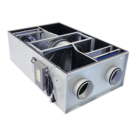
Figure 2.1. VENCO Heat Recovery Units
READ THE INSTRUCTION BEFORE START-UP THE UNIT and KEEP IT IN
PROXIMITY OF THE UNIT and WITHIN EASY REACH OF SERVICE TECHNICIAN.
THE APPLIER WILL BE RESPONSIBLE FOR DEFECTS OCCURED DUE TO
OPERATING THE UNIT BY NOT AUTHORIZED PERSONEL or USING THE SPARE
PARTS WHICH ARE NOT ORIGINAL.
THE UNIT MUST BE OPERATED APPROPRIATE APPLICATIONS FOR PURPOSES
DESIGN and TECHNICAL SPECIFICATIONS
THE UNIT MUST NOT USED IN THE ENVIROMENTS WHERE CORROSION and
EXPLOSIVE GASSES EXIST

2019.10 5 / 31
Heat Recovery units as standard consist of five different parts as described; Exhaust Fan, Supply Fan, Fresh
Air Filter, Exhaust Air Filter, Plate Type Heat Recovery Exchanger.
Figure 2.2. Heat Recovery Unit Schema
Figure 2.3. Heat Recovery Unit Schema (Plug)
Fresh Air Fan, Direct
Driven
Drain Pan
Exhaust Air Fan, Direct
Driven
Heat Recovery Plate
Exchanger
Filter
Filter
Fresh Air Fan,
Direct Driven
Drain Pan
Exhaust Air Fan,
Direct Driven
Heat Recovery Plate
Exchanger
Filter
Filter

2019.10 6 / 31
3. TECHNICAL SPECIFICATION for HEAT RECOVERY UNITS
Technical specifications, which are valid for the heat recovery units as standard manufactured by VENCO, are
given in the table below.
Table 3.1.1 Technical Specifications for VHR Models
MODEL
VHR
04
VHR
07
VHR
09
VHR
11
VHR
16
VHR
20
VHR
23
VHR
29
VHR
36
VHR
51
Air Flow 0 Pa*
m³/h
493
770
925
1238
1620
2025
2310
2852
3678
4857
Air Flow 150 Pa*
m³/h
299
595
790
1045
1320
1790
2045
2370
3137
3750
Efficiency
%
Efficiency up to 70%, depending on working conditions
ELECTRICAL
Voltage
230Volt / 50Hz
Power
Watt
104
204
310
420
450
1030
1030
1100
1.100
1100
SFP**
1,15
1,09
1,18
1,27
1,23
2,00
1,76
1,67
1,26
1,41
Air Filter
Synthetic Filter –For Exhaust and Fresh Air
OOPTIONAL
Electrical Heater
kW
1
230 V
1~
2
230 V
1~
3
230 V
1~
3
230 V
1~
4
400V
3~
5
400 V
3~
6
400 V
3~
7
400 V
3~
10
400 V
3~
12
400 V
3~
*External static pressure
**According to EN 13779

2019.10 7 / 31
Table 3.1.2 Technical Specifications for VHR EC Models
MODEL
VHR
04 EC
VHR
09 EC
VHR
11 EC
VHR
16 EC
VHR
29 EC
VHR
36 EC
VHR
51 EC
Air Flow 0 Pa*
m³/h
547
1252
1468
2261
2858
3810
4993
Air Flow 150 Pa*
m³/h
428
1091
1058
2112
2657
3534
4742
Efficiency
%
Efficiency up to 70%, depending on working conditions
ELECTRICAL
Voltage
230Volt / 50Hz
Power
Watt
110
340
340
1050
1220
1560
2600
SFP**
1,004
1,102
1,196
1,684
1,508
1,412
1,752
Air Filter
Synthetic Filter –For Exhaust and Fresh Air
OOPTIONAL
Electrical Heater
kW
1
230 V
1~
3
230 V
1~
3
230 V
1~
4
400V
3~
7
400 V
3~
10
400 V
3~
12
400 V
3~
*External static pressure
**According to EN 13779
VHR Heat Recovery Units are controlled with Standard Electronic Controller (SEC), supplied as standard with
the unit. The supply air fan and return air fan are driven as 5 speeds with SEC. Also the electrical heater
(optional) can be controlled by SEC manually or automatically depending on the room set temperature, has a
protection system (optional) against the frost formation at the temperatures below -5°C, and Pressure Sensor
(optional) for clogged filter.
Functional Electronic Controller (FEC) could be supplied optionally. Moreover to SEC, CO2sensor or air quality
sensor could be optionally connected. The fan speed automatically changes by regarding to the sensor value.
All controllers have a digital input for Building Management System or VRF (VRV) System and also have a
digital output for the unit status information.

2019.10 8 / 31
Table 3.2. Dimensions for VHR and VHR EC Models

2019.10 9 / 31
MODEL
VHR 04
VHR 07
VHR 09
VHR 11
VHR 16
VHR 20
VHR 23
VHR 29
VHR 36
VHR 51
Length [mm]
L
800
900
900
940
1115
1125
1125
1.400
1.450
1.650
Width [mm]
W
740
860
860
1020
1030
900
900
980
1.100
1160
Height [mm]
H
295
335
335
450
430
425
425
420
595
690
Duct Connection
[mm]
Ød
Ø160
Ø200
Ø200
Ø200
Ø300
Ø300
Ø300
Ø355
Ø400
Ø450
Weight [kg]
28
40
40
63
65
76
76
104
145
160
Service
Clearance [mm]
Ls
400
450
450
500
550
550
550
450
450
500
MODEL
VHR 04
EC
VHR 09
EC
VHR 11
EC
VHR 16
EC
VHR 29
EC
VHR 36
EC
VHR 51
EC
Length [mm]
L
800
900
940
1115
1.405
1450
1655
Width [mm]
W
735
860
1020
1030
1115
1100
1265
Height [mm]
H
290
330
445
430
430
595
700
Duct Connection
[mm]
Ød
Ø160
Ø200
Ø200
Ø300
Ø355
Ø400
Ø450
Weight [kg]
28
40
63
65
90
140
155
Service
Clearance [mm]
Ls
400
450
500
550
550
600
600

2019.10 10 / 31
4. WORKING CONDITIONS
The heat recovery units effectively work at the temperatures between -5°C and +40°C at the relative humidity
80%. The unit is not applicable for the corrosive conditions. For different working conditions, please contact
with VENCO.
If there is no frost protection on the unit and the outside temperature is less than -5°C, the unit must be stopped
and you should contact with VENCO. The condense water can be frozen at the temperature less than -5°C
and it can damage the exchanger.
With frost protection system, units can work at the temperature between -30°C and +40°C at the relative
humidity 80%. With the frost protection case; if the exchanger thermostat senses below -5°C, exhaust fan
jumps to highest speed, and fresh air fan drops to lowest speed. And there is a warning message “Frost
Protection” popups on the controller screen. The unit functions and the controller screen rolls back to normal
situation, when the exchanger thermostat senses above -5°C.
5. TRANSPORTATION –STORAGE –INSTALLATION
All heat recovery units by manufactured VENCO are controlled and tested according to the standards before
the transportation.
During transportation, lifting and landing, heat recovery units are damaged especially due to wrong methods
usage. Appropriate lifting methods should be used in order to minimize any possible damage. Transpallet or
forklift can be used for lifting or transporting small units. Lifting and transportation should be done with trained
and experienced personnel and security precautions should be taken to prevent the unit to fall over or slide.
During lifting and transportation of the unit, nobody should stay under the unit or in the front of the unit (Figure
5.1.).
Figure 5.1. Lifting Schema
During Storage; heat recovery units have to be kept in a closed area where the heat should be between –20
ºC and + 40 ºC and relative humidity should not exceed 80%. Also the unit should be kept away from dust,
gas, corrosive streams and effects causing corrosion.
During Installation; EN 60204-1 rules should be implemented during the final assembly. Before the installing
of heat recovery units, customers should control whether weight and dimensions of the stations are suitable
for the places from where stations will pass through and assembly will be carried out.There should be sufficient
amount of place around the unit to be able to give service and for piping connections. Heat recovery units
should be assembled onto a hard and flat base.
Damages due to wrong transportation-storage-installation are not covered under warranty.

2019.10 11 / 31
Figure 5.2. Installation Schema
Figure 5.3. Connection Schema (Top View)
Rot
Filter
Service
Doors
Service Door
Electrical
Connection
Box
OUTDOOR
Exhaust Air
OUTDOOR
Fresh Air
INDOOR
Fresh Air
Model L1
min.
[mm]
VHR 04/04EC
400
VHR 07
450
VHR 09/09EC
450
VHR 11/11EC
500
VHR 16/16EC
550
VR 20
550
VHR 23
550
VHR 29
VHR 29 EC
450
550
VHR 36
VHR 36 EC
450
600
VHR 51
VHR 51 EC
500
600
INDOOR
Exhaust Air
Service Zone

2019.10 12 / 31
Figure 5.4 Connection Schema
6. CONNECTIONS
6.1. DUCT CONNECTIONS
Return air, fresh air, exhaust air and supply air ducts should be fixed (connected) to the unit with flexible
connection. Required leak-proofing should be obtained in order to ensure desirable air flow. Having improper
(bad) unit –duct connections and wrong dimension, shape and duct fragments inside of the connection may
cause a turbinated air flow.
When air flow direction is changed at fan blowing outlet, excessive losses may occur. If this is compulsory,
connections should be done as Figure 6.1.1. The length of duct, before the elbow or electrical heater, should
be double of the outlet-diameter.
Figure 6.1.1. Duct Connections Schema (Changing the direction of air flow)
INSIDE
Fresh Air
INSIDE
Exhaust Air
OUTSIDE
Fresh Air
OUTSIDE
Exhaust Air
Electrical Duct
Heater
Connection Duct
L = 2 D

2019.10 13 / 31
6.2. DRAIN CONNECTIONS
The diameter of drain pipe should be equal the diameter of drain pipe on the unit. Drainage pipe and drain pan
connections should be made by ripple and flange to be able to dismantle pipe connections easily in order to
clean up the residue occurred on drain pan and pipes.
The pipe coming out of the drain pan should be connected to a U or P shaped flusher pipe and should be filled
with water in order to not to cause air suction as described below.(Figure 6.2.2.)
Figure 6.2.2. P-Shaped Flusher Application
6.3. ELECTRICAL CONNECTIONS
All electricity connections should be designed and prepared according to EN 60204 –1 Standards. The
electrical materials, cables and all relevant control and remote control equipment should be chosen and
designed suitable to unit peculiarities and requirements. Electrical wiring diagram is given in Figure 19.1 –
Appendix 1.
7. SAFETY REQUIREMENTS
VENCO heat recovery units are produced according to EN 60204-1 Standards and MD 98/37 EC numbered
European Union Directives and carry the CE signs on themselves. However, the unit can be dangerous if the
unit is not used or the service is given by trained and experienced technicians, and indicated security
ALL ELECTRICAL CONNECTIONS SHALL BE DONE ACCORDING TO EN 60204-1
BY TRAINNED AND AUTHORIZED PERSONEL
ELECTRICAL CONNECTIONS ARE READY FOR PLUG-IN CONNECTION. DO NOT
CUT CABLE AND PREPARE PROPER EQUIPMENT TO CONNECT.

2019.10 14 / 31
precautions are not followed. For this reason the necessity was felt to explain security rules of heat recovery
units and explain possible dangers and precautions.
Possible dangers related to heat recovery units are as follow;
Dangers directed to operator security
Dangers directed to unit damage
Dangers directed to unit operation productivity.
Never expose the unit to moisture, strokes and external effects.
The unit should not be used in the environment where corrosion and explosive gasses exist.
The unit should be maintained by trained technicians.
Do not repair or adjust, when the unit is running.
Turn the electrical switch off and wait for the motor blades stop, before open the unit.
Never expose fans, cables and connections to the water.
If the outside temperature is less than -5°C, the unit must be stopped and you should contact with VENCO.
The condense water can be frozen at the temperature less than -5°C, it can be damaged to the exchanger.
Do not operate the unit, when the access doors open and the duct connections are not completed.
8. SAFETY LABELS
Necessary warning labels are placed onto unit for the users or service personnel. When the unit is put into the
operation, following stickers have to be controlled whether they are existing or not.
Figure 8.1. Manuel label
Figure 8.2. Electrical warning
label
Figure 8.3. Temperature
warning label
Figure 8.4. Repair warning label
Figure 8.5. Wiring diagram label

2019.10 15 / 31
Figure 8.6.Ground label
Figure 8.7. Fan label
Figure 8.8.Electrical warning
label
Figure 8.9. Access door label
Figure 8.10. Filter access door
label
Figure 8.11. Drain label
Figure 8.12. Fresh air label
Figure 8.13. Exhaust air label
Figure 8.14. Air flow direction
label
9. CONTROLS BEFORE START-UP
Please make sure that all electricity cables are made according to (EN 60204 -1) standards and security
and protection units belong to all elements.
Please make sure that all parts of the unit are clean. There can be duct insulation residuals, bands etc.
If the outside temperature is less than -5°C, the unit must be stopped and you should contact with VENCO.
The condense water can be frozen at the temperature less than -5°C, it can be damaged to the exchanger.
Following points have to be controlled periodically.
Isolation materials used for heat and sound isolations
Cable isolation
Control panel
Electrical cables and other electromechanical parts
Metal and painted surfaces
Connection elements such as screw, turn screw and joint washer
FILTERS; Maintenance of the filters should be done regularly. Dirty filters can decrease air flow and
consequently the capacity. Synthetic or metal filters can be cleaned or washed. However it is advised to change
synthetic filters every two years. While changing other type filters; bag, hepa filters with the new ones, new
ones should have same dimension, type and features.
HEAT RECOVERY EXCHANGER; is controlled before transportation. The plates of heat recovery exchanger
should be checked, after transportation.
FANS and MOTORS; Wiring shallbe done, according to internationalstandards.The turning way offan-blades
should be checked, according to the air-flow direction label on the fan.

2019.10 16 / 31
10. TRAINING of TECHNICIANS
Assembly, putting into operation and maintenance works can only be done by authorized and trained
technicians. The technician has to be informed by the owner of the unit or it’s user about possible dangers
he/she may face during following phases:
Electrical Connections
Duct Connections
Putting Into Operation
Maintenance
For the continuity of the warranty, control and maintenance responsibilities have to be accepted and followed
strictly. You can apply to VENCO A.S. to train your authorized technicians.
11. RECOMMENDATIONS FOR SAFETY
This user manual is prepared to provide correct usage and assembling of the heat recovery unit and warn the
maintenance personnel for the possible dangers they may face. Apart from instructions and warnings of the
producers, legal rules and standards have to be taken into consideration as well.
12. START-UP
Instructions have to be followed before operating the unit first time (or after yearly maintenance). Additionally
following controls have to be followed.
Please make sure that all parts of the unit are clean. There can be duct insulation residuals, bands etc.
Please make sure that all electrical cables are made according to (EN 60204-1) standards and security
and protection units belong to all elements.
Please take out filters after the first operation and clean them properly. Then insert the filters in it.
If all access doors are taken out during the assembly, please make sure that service doors are closed.
Control the adjustment of thermal over load relay. Give electricity and provide the fan to operate in the highest
speed. Control the following points carefully:
Unexpected noise
Motor current and voltage values
13. MAINTENANCE
Protection maintenance program is an important part of an effective security program. Maintenance works
have to be carried out by experienced and trained personnel with wearing protection clothing. Please do not
try doing any maintenance before switching off the electricity and having fan security.Generally heat recovery
units do not require special maintenance apart from its routine cleaning and maintenance. Maintenance period
changes according to work conditions. Advised maintenance program is given below:
Drain Outlet; once in 3 months, please check water flow from drain pipe.
Air Filters; once in 3 months, please check the filters. Please wash it or change it when necessary.
Fans and Motors; Once every-season, please check them by opening access door.

2019.10 17 / 31
Wiring and Electrical Connections; Once a year, please check the ampere, the voltage.
Construction and Housing; Once a year, please check it for resistance to corrosion.
Heat Recovery Exchanger; Once in two years, check it by taking it out for preventing creation of high
pressure. Exchanger can be cleaned by using the warm water & light detergent. After cleaning, all plates
surface of exchanger should be dried.
14. CONTROL FUNCTIONS
14.1. Standard Electronic Controller (SEC)
Figure 14.1.1. Standard Electronic Controller (SEC)
VENCO VHR type heat recovery unit control functions are;
Unit ON / OFF
FAN 1 ( Supply fan ) Speed control as 5 steps and automatic
FAN 2 ( Exhaust fan) Speed control as 5 steps and automatic
Heat, cool and fan mode

2019.10 18 / 31
Table 14.1.1. Electronic Controller Buttons
Buttons
Name
Description
ON / OFF
Unit will be ON or OFF.
MODE
Select Running Status
(Cool , Heat or Ventilation )
Fan
Increase, decrease selected fan’s stage value.
Value Increase
Increase of set value. Increases the value of selected by
fan button area.
Value Decrease
Decrease of set value. Decreases the value of selected
by fan button area.
Using the mode button, you can make the mode (Heat, cool and fan) selection. If the fan button is pressed,
makes of the fresh air fan speed control (1 / 2 / 3 / 4 / 5-automatic). When the fan button is second pressed,
makes of the exhaust fan speed control (1 / 2 / 3 / 4 / 5-automatic). If fans are running automatically, (A) icon
appears on the screen. Fans automatically run in heating and cooling mode. Air quality and CO2sensors have
to be connected for automatic run of the fans.
While in fan mode, fans don’t automatically run. If the fans automatically run in different modes, when switched
to fan mode automatic run is stop. Steps manually set with controller.
Electronical Controller Functions:
–Device ON / OFF
–Stage control of FAN1( fresh air fan) (OFF / 1 / 2 / 3 / 4 / 5 / AUTO)
–Stage control of FAN2( exhaust fan) (OFF / 1 / 2 / 3 / 4 / 5 / AUTO)
–Heat, cool and fan mode
Note: When electrical heater is working, FAN1 or the device is shutdown; FAN1 will work at stage 5 for 30
seconds to cool electrical heater. Electrical heater will not work when FAN1 is OFF.
Electrical heater only runs in the heat mode which runs automatically depends on the room temperature and
set point. When the heater runs in step one “ST 1” icon appears on the screen. When the heater runs in step
two “ST 1+2” icon appears on the screen. Fresh air fan will run at step 5 for 30 seconds to cool electrical heater.
Electrical heater will not run when fresh air fan is off.

2019.10 19 / 31
SEC electronical controller can perform device ON / OFF from the dry contact information it gets from the
building automation system or similar system (VRV, VRF controller, timer etc.). By a dry contact on the relay
card connected to the BMS input; when dry contact is ON (short circuit) the device is activated and starts to
work in the position where previous closed. In this case, by using the front panel interfering device ON /OFF
equipment position change operations can be performed. When the dry contact is off, the device closes down
and you can’t interfere to the device from the front panel.
When the optional filter sensor detects the dirty filter, ‘’AL 03’’ warning will be shown on screen. When this
warning is shown, the device will run properly, however the warning will be shown until the filters are cleaned.
Optionally, there is a system which prevents freezing plated heat recovery under low temperature. When icing
is determined in the plated heat exchanger, fresh air fan will stop and exhaust fan will work at maximum stage
for defrosting. After defrosting, the device will return to its normal working conditions. Under these
circumstances ‘’AL 07’’ will be shown on screen. Commands from the front panel will not run.
Optionally, there is By-pass damper control. Damper will be automatically ON or OFF position depending on
the outdoor and room temperature information. If fan is selected in by MODE the damper is OFF.
Optionally, there is a control of air quality.
The fan in AUTO (FAN1, FAN2 or BOTH) changes fan speed according to the information from sensors.
14.2. Functional Electronic Controller (FEC)
VENCO VHR type heat recovery unit control functions are;
Unit ON / OFF
FAN 1 ( Supply fan ) Speed control as 5 step and automatic
FAN 2 ( Exhaust fan) Speed control as 5 step and automatic
Heat, cool and fan mode
Image 14.2.1. Electronic Controller Buttons
Button
Name
Description
ON / OFF
Unit will be ON or OFF.
MODE
Select Running Status
(Cooll , Heat or Fan )
FAN
Fan1 and FAN2 stepped control
button.
Value Increase
Increases of the set value.
Increases the value of selected by
fan button area.

2019.10 20 / 31
Value Decrease
Decreases of the set value.
Decreases the value of selected by
fan button area.
Icons
Description
Heater and cooler step (ST 1 - ST 1+2)
Failure reporting (AL 01 - AL02 - AL 03)
Fresh air fan step (0-1-2-3-4-5-automatic)
Exhaust fan step (0-1-2-3-4-5-automatic)
Using the mode button, you can make the mode (Heat, cool and fan) selection. If the fan button is pressed,
makes of the fresh air fan speed control (1 / 2 / 3 / 4 / 5-automatic). When the fan button is second pressed,
makes of the exhaust fan speed control (1 / 2 / 3 / 4 / 5-automatic). If fans are running automatically, (A) icon
appears on the screen. Fans automatically run in heating and cooling mode. Air quality and CO2sensors have
to be connected for automatic run of the fans.
While in fan mode, fans don’t automatically run. If the fans automatically run in different modes, when switched
to fan mode automatic run is stop. Steps manually set with controller.
Electrical heater only runs in the heat mode which runs automatically depends on the room temperature and
set point. When the heater runs in step one “ST 1” icon appears on the screen. When the heater runs in step
two, “ST 1+2” icon appears on the screen. Fresh air fan will run at step 5 for 30 seconds to cool electrical
heater. Electrical heater will not run when fresh air fan is off.
Optional air cooler battery only runs in cool mode which runs automatically depends on the room temperature
and set point.
Optional damper runs in heat and cool mode which runs automatically depends on the room temperature and
set point. If fan mode is active, damper is off.
FEC electronical controller can perform device ON / OFF from the dry contact information it gets from the
building automation system or similar system (VRV, VRF controller, timer etc.). By a dry contact on the relay
card connected to the BMS input; when dry contact is ON (short circuit) the device is activated and starts to
work in the position where previous closed. In this case, by using the front panel interfering device ON /OFF
equipment position change operations can be performed. When the dry contact is off, the device closes down
and you can’t interfere to the device from the front panel.
Optionally, there is a system which prevents plated heat recovery from freezing under low temperature. When
icing is determined in the plated heat exchanger, fresh air fan will stop and exhaust fan will run at maximum
Other manuals for VHR Series
2
This manual suits for next models
18
Table of contents
Other VENCO Heating System manuals
Popular Heating System manuals by other brands

therm-ic
therm-ic Integration Mono button BLE manual

Energotech
Energotech EnergoInfra Industry EIR3000 Mounting and installation

Imetec
Imetec E0809 operating instructions

Shop-Vac
Shop-Vac AM425-HV user manual

Vaillant
Vaillant ecoTEC plus SERIES Setup instructions

NuAire
NuAire MRXBOX-ECO installation manual

Broan
Broan ERV120T installation guide

EverHot
EverHot BL1 Series Technical manual

MEDC
MEDC XB11 Technical manual

Valeo
Valeo THERMO DC 200 Installation and operating instructions

American Standard
American Standard AERVR100A9P00A Installer's guide

Palazzetti
Palazzetti ECOMONOBLOCCO WT R Use and maintenance manual