2016.09 1 / 28
Index
1. INTRODUCTION...................................................................................................................................3
2. HEAT RECOVERY UNITS and VHR MODELS.....................................................................................3
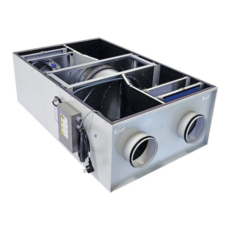
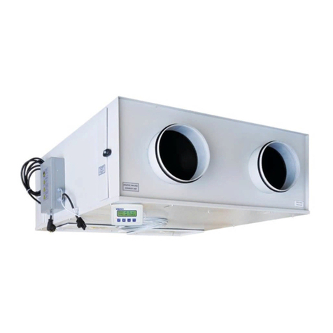
Figure 2.1.1 VENCO VHR DX HEAT PUMP HEAT RECOVERY UNIT.....................................................3
Figure 2.2.1 Heat Pump Heat Recovery Units Parts .................................................................................4
3. TECHNICAL SPECIFICATION for HEAT RECOVERY UNITS..............................................................5
Table 3.1. VHR DX Heat Pump Heat Recovery Unit Technical Specifications ..........................................5
Table 3.2. Dimensions for VHR DX Heat Pump Heat Recovery Unit.........................................................6
4. WORKING CONDITIONS......................................................................................................................7
5. TRANSPORTATION –STORAGE –INSTALLATION...........................................................................7
5.1.Transportation ........................................................................................................................................7
Figure 5.1.1 Lifting Schema ......................................................................................................................7
5.2Storage..............................................................................................................................................7
5.3 Installation..........................................................................................................................................8
Figure 5.3.1. Connection Schema.............................................................................................................8
Figure 5.3.2. Installation Schema..............................................................................................................8
Figure 5.3.3. Installation Schema..............................................................................................................9
6. CONNECTIONS..................................................................................................................................10
6.1. Duct Connections.............................................................................................................................10
Figure 6.1.1 In.Free Outlet......................................................................................................................10
Figure 6.1.2. Ducted Outlet.....................................................................................................................10
Figure 6.1.3. Unit Duct Connection .........................................................................................................10
6.2. Drain Connections ...........................................................................................................................11
6.3. Electrical Connections......................................................................................................................11
7. SAFETY REQUIREMENTS.................................................................................................................12
7.1. Warnings and Precautions...............................................................................................................12
7.2. Warning Labels................................................................................................................................12
Figure 7.2.1. Manuel Label......................................................................................................................12
Figure 7.2.2. Electrical Warning Label.....................................................................................................12
Figure 7.2.3. Temperature Warning Label...............................................................................................12
Figure 7.2.4. Repair Warning Label.........................................................................................................13
Figure 7.2.5. Wiring Diagram Label.........................................................................................................13
Figure 7.2.6. Ground Label .....................................................................................................................13
Figure 7.2.7. Fan(Spinning) Label........................................................................................................13
Figure 7.2.8. Electrical warning Label...............................................................................................13


