VenMill Industries HYBRID 2.0 User manual

2.0
User’s Manual
Covers setup, getting to know your
machine, alerts & warning, repairing an
optical disc, safety & cleaning, and FAQs
Rev 1.1

2
This unit is intended to clean/repair the
following discs: Blu-Ray, CD-ROMs, Music CDs,
Data CDs, DVDs, HD-DVDs, Computer Discs,
Game Discs, Books on disc, all recordable CDs
and DVDs, and double-sided discs.
THANK YOU
For purchasing the HYBRIDTM
2.0
© 2014 VenMill Industries, Inc. All rights reserved. Under the copyright laws, this manual may not be copied, in
whole or in part, without the written consent of VenMill.
Every eort has been made to ensure that the information in this manual is accurate. VenMill is not responsible
for printing or clerical errors.
Names and designs are trademarks of VenMill Industries, Inc. Artwork and Design © 2014 VenMill Industries, Inc.
All Rights Reserved.
The maximum amount of repairs per bottle may vary based on cleaning cycle usage. See www.venmill.com for
more information.
CAUTION: Units and consumables are designed for use in specic regions. Your warranty will be voided if you
purchase the equipment and/or consumables outside of your designated region. Purchase only through Authorized
Distributors found on our website at www.venmill.com. If uncertain, please contact [email protected].
VenMill Industries, Inc
36 Town Forest Road
Oxford, MA 01540 USA
USA 800-928-0090
No. Am. 866-864-0210
www.venmill.com
SAVE ALL PACKING MATERIALS. FAILURE TO
USE PACKAGING DESIGNED FOR THIS UNIT
MAY CAUSE DAMAGE TO THE UNIT AND WILL
VOID WARRANTY. FOR MORE INFO CONTACT
SUPPORT@REFACE.COM.AU

3
READ BEFORE OPERATING EQUIPMENT
SECTION 1
Unpacking ..........................................................................................................................4
SECTION 2
Getting to Know Your Unit............................................................................................5
SECTION 3
Initial Setup ........................................................................................................................7
SECTION 4
Quick Start ....................................................................................................................... 11
SECTION 5
Modes of Operation ..................................................................................................... 12
SECTION 6
Notications.................................................................................................................... 14
SECTION 7
Standard Maintenance................................................................................................ 16
How to Replace the Bung Pads.................................................................... 16
How to Replace the Center Hub...................................................................... 17
How to Rell the Water Bottle.......................................................................... 17
How to Replace the Bung Solution Bottle .............................................. 18
When to Empty the Catch Tray ........................................................................ 19
How to Clean the Catch Tray............................................................................. 19
How to Replace the Jet Nozzle Extender ..................................................... 20
How to Unclog the Jet Nozzle Extender....................................................... 20
How to Replace the Consumable Counter Chip (C-H Chip) .................. 21
SECTION 8
Repacking ........................................................................................................................ 23
SECTION 9
Hybrid 2.0 FAQs.............................................................................................................. 25
SECTION 10
Specications.................................................................................................................. 27

4
SECTION 1: Unpacking
SAVE ALL PACKING MATERIALS. FAILURE TO USE PACKAGING DESIGNED FOR
THIS UNIT WILL CAUSE DAMAGE TO THE UNIT AND WILL VOID WARRANTY.
Parts that need to be saved are as follows:
VMI Hybrid Shipping Box | Top Cardboard Insert | Left & Right Side Packing
Foams | Protective Plastic Bag
Replacement packing materials are available for purchase from VenMill
Industries if they are discarded.
1. Open the Shipping Box.
2. Remove the Top Cardboard Insert -
which contains the machine’s starter
supplies, accessories, and support
documents.
3. Remove the Hybrid from the shipping
box.
4. Remove the Left and the Right side
packing foams.
5. Take the Hybrid out of the protective
plastic bag.

5
SECTION 2: Getting to Know Your Unit
Bung Pads
Jet Nozzle Extender
Catch Tray
Platen Assembly
Center Hub
Keypad
Pumps
Bung Solution
C-H Chip
Back Panel Door
On/O
Switch
Power
Inlet
Water

6
Operation minutes per set of supplies:
Bung Pads: 84 minutes of operation
Center Hub: 84 minutes of operation
Jet Nozzle Extenders: 500 minutes of operation
Water Bottle: 100 minutes of operation
Bung Solution: 250 minutes of operation
C-H Chip: 500 minutes of operation
Supplies for the Hybrid come in a combo pack good for 500 minutes of use. The
components of the combo pack have to be replaced at the following intervals:

7
SECTION 3: Initial Setup
1. Install Counter Chip:
Locate the RS232 port on the front left hand side
of the machine.
Take the C-H Chip, which has been provided with
your machine, and install it into this port.
The VMI Hybrid unit will recognize this chip, once
the machine is powered on.
2. Fill the Water Bottle:
Locate the Back Panel Door, on the backside
of the machine, and pull down on this door to
access the Bung Solution and Water Bottle
compartment.
Find the Water bottle, located inside this
compartment.
Remove the Water bottle from the machine and
ll as shown in the corresponding picture. Note:
This bottle can be lled with any potable water.
Also included inside of this compartment, on
the back wall are markings branded into the
back wall indicating which tube is for the Bung
Solution and which tubing is for the Water. Locate
the Water tube.
Feed the designated tube through the Water
bottle cap. Note: Make sure the tube reaches the
bottom of the bottle and make sure not to pinch
the tube.

8
3. Install Bung Solution Bottle:
Two bottles of Bung Solution have been
provided with your machine. Find the bottle of
Bung Solution which has an opening for tubing
in its cap. Note: Only one of the two Bottles of
Bung Solution contains a cap with an opening
for tubing. This cap must be saved for reuse.
Before installation, it is essential to shake this
bottle well!
Once you have shaken the bottle, unscrew the cap, and remove the internal
Safety Seal. Note: Please keep this Safety Seal! Reinstall the cap.
Also located inside of the bottle compartment, on the back side of the
machine, are markings indicating which tube is for the Bung Solution.
Locate this tube.
Feed the designated tube through the Bung Solution bottle cap. Note: Make
sure the tube reaches the bottom of the bottle and make sure not to pinch
the tube.
Close the back panel door.
Reminder: Please keep the Shipping Cap (this does not have an opening for
tubing) and the Safety Seal. Should the machine need to be sent in for servicing,
the Bung Solution bottle must be removed. To ensure that the solution will not
cure, you will need to make sure that the bottle is sealed and capped.
4. Install Power Cord:
Insert the power cord into the power inlet on the
back of the machine.
Take the other end of the power cord and plug it
into a wall outlet.
On the back side of the machine, turn the ON/
OFF switch to the ON position.(After a couple of
seconds, the Top Cover will automatically open.)
Leave the Top Cover in the open position.

9
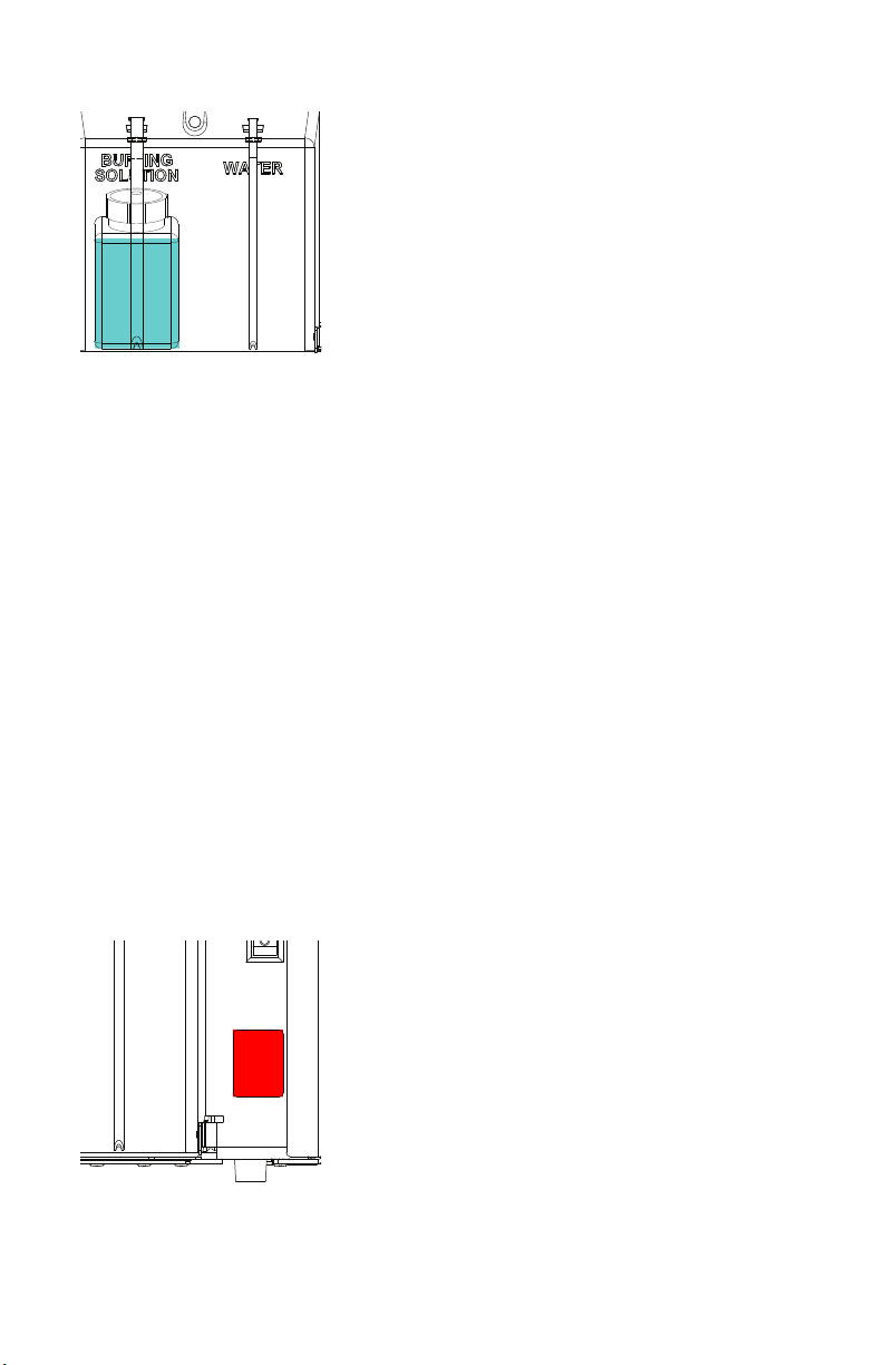
5. Prep Bung Solution and Water Lines:
Warning: Failure to prep the Bung Solution &
Water lines will cause damage to both the disc
and the Bung Pads!
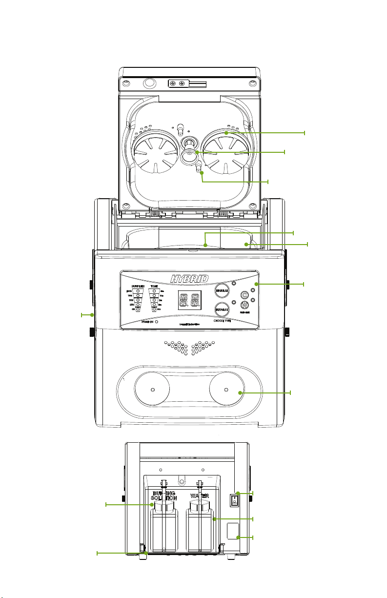
The top cover must be in the open position to
perform these steps. Have a paper towel or small
container ready, in order to catch the Bung
Solution and the Water, which will come from the
tube nozzles.
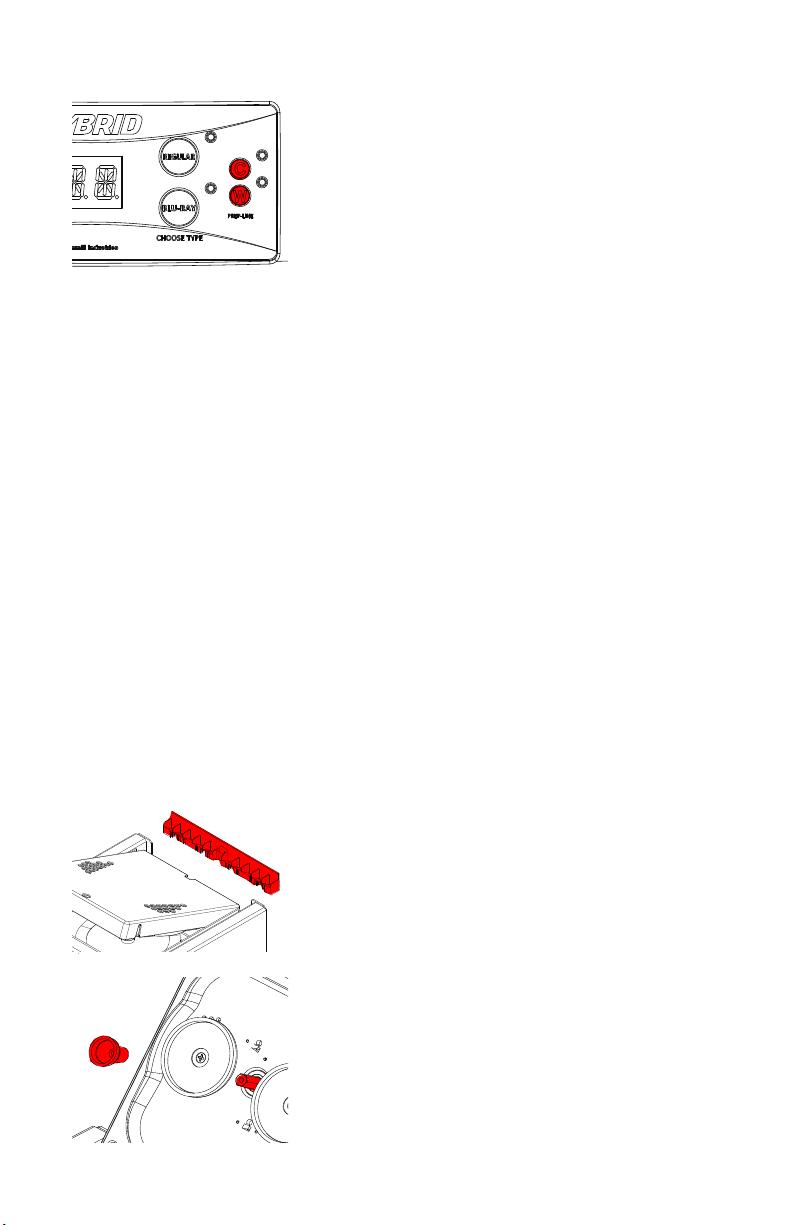
Locate the two smaller buttons, labeled“C”& “W”, on the front User Keypad.
“C” = Bung Solution & “W”= Water.
To activate the prepping process, press either the “C” or the “W” button. Note:
Both lines can be prepped at the same time.
Once the prepping process has been activated, tilt the Top Cover down
toward you, at about a 45 degree angle. (Note: Make sure that the Platen
Assembly is installed, so that solution and water does not pour directly onto
the shaft of the main motor!) This will ensure that the solution and the water
drips out of the nozzles and onto the paper towel.
Once the Bung Solution and the Water comes out of the designated tube
nozzles and there is no more air left in the lines, press the“C” and the “W” button
to stop the prepping process. Leave the Top Cover in the Open position.
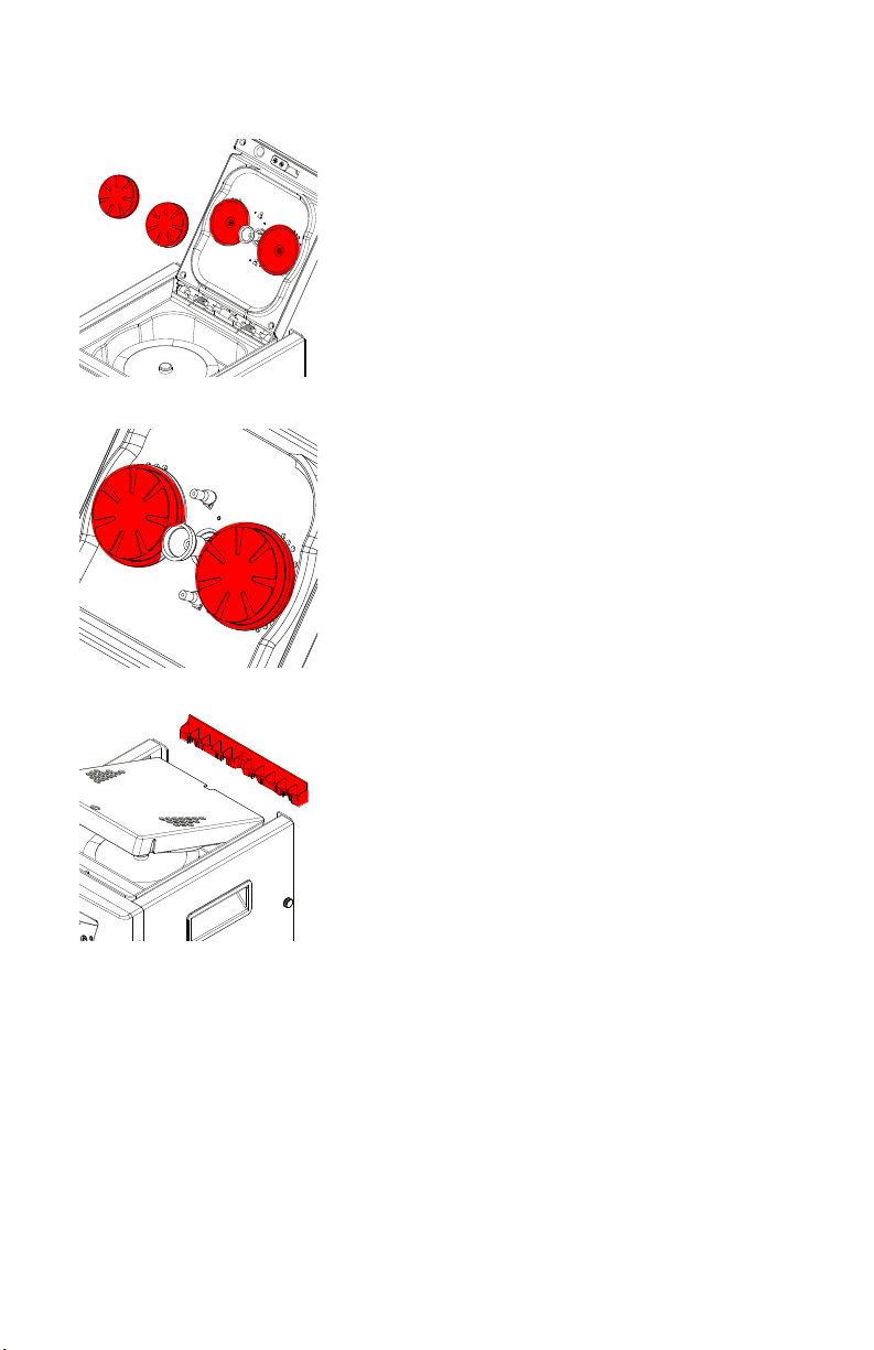
6. Install the Center Hub:
Locate and remove the Lid Stopper. Let the Top
Cover gently open to its farthest position. Locate
the Hex shaped post between the two Bung
Pad holders.
Take a Center Hub and line up the hex shaped
opening on the hub with the hex shaped
post. Push the Center Hub into place. Spin the
Center Hub by hand to make sure that the hub
is installed properly. The Center Hub should
not wobble when it spins. If needed, make an
adjustment. Leave the Top Cover in the Open
position.

10
7. Install the Bung Pads:
Locate the two Bung Pad Holders.
Take one set of new Bung Pads.
Each Bung Pad has been marked on the back
side with an “L”or an “R”, to indicate which Bung
Pad should go on which Bung Pad Holder.
Note: Orientation of the machine is from the
prospective of the Operator facing the front of
the unit. The “R” (RIGHT) Bung Pad is larger in
size than the“L” (LEFT) Bung Pad.
Install each Bung Pad onto the Bung Pad
Holders. Make sure that each Buer Pad is
centered and fully seated on the Bung Pad
Holder.
Reinstall the Lid Stopper.
Caution: It is essential to keep the Top Cover in
the Open position when the machine is in the
“Stand By”mode and when the machine is not
in use! This will ensure that the Bung Pads will
not become at, which would aect the repair
process, and would cause an error message to
display. If you would like to keep the Top Cover
closed, when the machine is not in use, make
sure to remove the Platen Assembly.
Your VMI Hybrid unit is now ready to be used!

11
SECTION 4: Quick Start – How to Use Your Machine
1. Turn ON power to the unit by pressing
the ON/OFF switch to the ON position,
located in the rear of the unit. The Top
Cover will open automatically after a
few seconds.
2. Select which type of disc you would
like to repair, by selecting either the
Regular or Blu-ray option, located on
the User Keypad.
3. Select the amount of time that you
would like to repair your disc for,
depending on the severity of damage.
To do this, press either the Regular
or the Blu-ray button repeatedly
(depending on what option you chose
in step #2) until the LED next to the
desired amount of time is illuminated.
4. Place disc onto the Platen Assembly,
with LABEL SIDE OF DISC FACING
DOWN!
5. Close the Top Cover and the cycle will
start automatically.
6. Once the cycle has completed, the Top
Cover will open automatically. Remove
your disc.

12
SECTION 5: Modes of Operation
Regular: This option encompasses any
of the following types of discs: CD-ROMs,
Music CDs, Data CDs, DVDs, HD-DVDs,
Computer Discs, Game Discs, Books on
Disc, all recordable CDs and DVDs, Mini
Discs (with adapter), & Double-Sided Discs.
Press the “Regular”button located on the
User Keypad to activate this operation. A Solid Green LED will appear next
to this option. The User Keypad will then prompt the User to select a length
of time. The User will have an option of time ranging from 30 seconds to 4
minutes, depending on the severity of damage on the disc. When the User
Keypad prompts the Operator to select a repair time, all the available time
for this option will ash on the“Time - Fuel Gauge”. To select the desired time,
press the“Regular”button repeatedly to indicate the desired time option.
When this is done the lights will stop ashing and only a solid light will appear
next to the time that has been selected. Next, close the Top Cover, and the
machine will start automatically.
Heavy: This option encompasses any of
the following types of discs: Blu-ray, PS3,
PS4, X-Box One, and Wii U discs.
Press the “Blu-ray” button located on the
User Keypad to activate this operation.
A Solid Green LED will appear next to
this operation. The User Keypad will then
prompt the User to select a length of time. The User will have an option
of time ranging from 1 minute to 4 minutes, depending on the severity of
damage on the disc. When the User Keypad prompts the Operator to select
a repair time, all the available time for this option will ash on the “Time –
Fuel Gauge”. To select the desired time, press the “Blu-ray”button repeatedly
to indicate the desired time option. When this is done the lights will stop
ashing and only a solid light will appear next to the time that has been
selected. Next, close the Top Cover, and the machine will start automatically.

13
Emergency Stop: At any time during a cycle, you may stop the cycle
prematurely by pressing any button on the User Keypad. Once the button
is pressed, the cycle will stop, and the Top Cover will open automatically.
The Main Screen will then display the“ER” error message indicating that the
Emergency Stop function has been successfully accomplished. Once the unit
has reset, the“ER” error message will disappear, and the machine will default
back to the last mode of operation that was selected. The Operator may now
continue using the machine.

14
SECTION 6: Notications
Replace All Consumables (RC):
The CH Chip has been designed to
monitor the consumables used within
your Hybrid, to ensure that each disc
is repaired to the same standard, and
to decrease any downtime that may
result from not having replacement
consumables on hand. Installation of
a new C-H Chip informs the unit that
the consumables have been replaced. The amount of consumable usage
is displayed on the“Supplies – Fuel Gauge” located on the User Keypad.
As the consumables deplete over time, the fuel gauge will expire down in
percentage as follows:
100% = 500 minutes
75% = 375 minutes
50% = 250 minutes
25% = 125 minutes
0% = 0 minutes
Once the consumable level has reached 25%, the Green LED will switch over
to Yellow, and the 0% Green LED will turn over to Red and will blink every two
seconds. At this point the Operator should obtain more consumables. Once
the C-H Chip has reached 0%, the ashing Red LED will stop and a solid Red
LED will appear. At this point the“RC” error message will appear on the Main
Screen. The machine will not perform any other operations until a new C-H
Chip is installed.
Once a new C-H Chip has been installed and power to the machine is turned
back on, then the “RC”error message on the Main Screen will disappear.
The“Supplies - Fuel Gauge” will display 100%. The machine is now ready to
resume operation.

15
Error Messages:
E1: Top Cover Closed / Switch still Activated.
E2: Main Motor is not achieving enough current.
E3: Main Motor is achieving too much current.
E4: Bung Solution Pump is not working.
E5: Water Pump is not working.
ER: Emergency Stop.
Required Actions:
AW: Add Water and Empty Catch Tray
CC: Replace Bung Solution & Clean Catch Tray
CP: Replace Bung Pads & Center Hub
RC: Replace all Consumables

16
SECTION 7: Standard Maintenance
How to Replace the Bung Pads
The machine will notify the Operator to replace
the Bung Pads by displaying the“CP”message
after 84 minutes of machine operation.
1. Make sure the Top Cover is in the“Open”
position.
2. Remove the Lid Stopper.
3. Let the Top Cover gently open to its farthest
position.
4. Locate the Bung Pads.
5. Pull back gently with your nger and thumb
on any outside edge on the Bung Pad. Pull the
Bung Pad away from the Bung Pad Holder,
until the pad is completely detached.
6. Repeat step #5 for the second Bung Pad.
7. Each Bung Pad has been marked on the back side with an “L”or an “R”, to
indicate which Bung Pad should go on which Bung Pad Holder. NOTE: THE
“R” (RIGHT) BUFFING PAD IS LARGER IN SIZE THAN THE “L”(LEFT) BUFFING PAD.
Take your new Bung Pad and line it up with the corresponding Bung Pad
Holder. Make sure that the new Bung Pad is fully seated by pressing gently
on the entire surface of the pad.
8. Repeat step #7 for the second Bung Pad.
9. If the Bung Pads were replaced due to the “RC” error code, no further
action is required with the Bung Pads.
10. If the Bung Pads were replaced due to the “CP” code, press the“Regular”
and then the “Blu-ray” buttons on the User Keypad to inform the machine that
the pads cover were replaced.
11. Leave the Top Cove in the Open position and continue to “How to Replace
the Center Hub” instructions.
FAILURE TO USE CONSUMABLES DESIGNED FOR THIS UNIT WILL CAUSE DAMAGE TO BOTH UNIT AND
DISC THEREBY VOIDING YOUR WARRANTY. FOR AUTHORIZED DISTRIBUTORS VISIT WWW.VENMILL.COM.

17
How to Replace the Center Hub
The Center Hub must be replaced at the same
time as the Bung Pads, when the machine gives
o the “CP” message. This will occur after about
84 minutes of machine operation.
1. Make sure the Top Cover is in the“Open”
position.
2. Locate the Center Hub.
3. Pull the worn Center Hub o of the Hex shaped
post with your Index Finger and Thumb.
4. Take the new Center Hub and line up the Hex
shaped opening on the hub with the Hex shaped
post.
5. Push the Center Hub onto the post.
6. Spin the Center Hub by hand to make sure the Hub is centered. The Hub
should not wobble as it spins. If needed, make the proper adjustment.
7. If you are replacing the Center Hub due to the “RC”message, then there are
no other steps that need to be performed.
8. If you are replacing the Center Hub due to the “CP” message, make sure to
also replace the Bung Pads, and then press the“Regular”and then the “Blu-
ray” buttons on the User Keypad to notify the unit that both the Bung Pads
and the Center Hub have been replaced.
9. Reinstall the Lid Stopper.
How to Rell the Water Bottle
The machine will notify the Operator to rell the Water after about 100
minutes of machine operation, by displaying the “AW”message.
1. Pull down on the Back Panel Door to expose the Bottles.
FAILURE TO USE CONSUMABLES DESIGNED FOR THIS UNIT WILL CAUSE DAMAGE TO BOTH UNIT AND
DISC THEREBY VOIDING YOUR WARRANTY. FOR AUTHORIZED DISTRIBUTORS VISIT WWW.VENMILL.COM.

18
2. Gently pull the bottom of the bottle back and
out of the machine.
3. Wipe down the Water tubing with a paper
towel to remove any excess water left on the
tubing.
4. Using any potable water, please ll the bottle
as shown in the corresponding picture.
5. Feed the designated water tubing through the cap. CAUTION: MAKE SURE
THE TUBING REACHES THE BOTTOM OF THE BOTTLE AND MAKE SURE NOT TO
PINCH THE TUBING!
6. Now that the water has been replaced, close the Back Panel Door.
7. Press the “Regular” button and then the“Blu-ray” button on the User
Keypad to notify the unit that the Water has been replaced.
How to Replace the Bung Solution Bottle
The machine will notify the Operator to replace the Bung Solution after
about 250 minutes of machine operation, by displaying the “CC”message. At
this time, the Catch Tray must be emptied and cleaned out.
1. Pull down on the Back Panel Door to expose
the Bottles.
2. Gently pull the bottom of the bottle back and
out of the machine.
3. Wipe down the Bung Solution tubing with a
paper towel to remove any excess solution left on
the tubing.
4. WARNING: BEFORE INSTALLING THE NEW
BOTTLE OF BUFFING SOLUTION – IT IS ESSENTIAL TO SHAKE THE BUFFING
SOLUTION BOTTLE WELL!
Once you have shaken the bottle, remove the Safety Seal from the bottle by
unscrewing the bottle cap. Once the safety seal has been removed, reattach
the bottle cap, and then proceed to feed the designated bung solution
tubing through the cap. CAUTION: MAKE SURE THE TUBING REACHES THE
BOTTOM OF THE BOTTLE AND MAKE SURE NOT TO PINCH THE TUBING!

19
NOTE: ONLY ONE OF THE TWO BOTTLES OF BUFFING SOLUTION CONTAINS A
CAP WITH AN OPENING FOR THE TUBING. PLEASE KEEP THIS SHIPPING CAP
AND SAFETY SEAL! SHOULD THE MACHINE NEED TO COME IN FOR SERVICING,
THE BUFFING SOLUTION BOTTLE MUST BE REMOVED. TO ENSURE THAT THE
BUFFING SOLUTION DOES NOT CURE YOU WILL NEED TO MAKE SURE THAT
THE BOTTLE IS SEALED AND CAPPED.
5. Now that the Bung Solution has been replaced, close the Back Panel Door.
6. Press the “Regular”button and then the“Blu-ray” button on the User Keypad
to notify the unit that the Water has been replaced.
When to Empty the Catch Tray
The machine will notify the Operator when to
empty the Catch Tray when the machine displays
the “CC”message. It is also suggested that this
action be performed when the machine displays
the “AW” message to add water to the Water
bottle. The Operator does not need to wait for
a cue from the machine to empty the Catch
Tray. The Catch Tray can be emptied at any time,
and should be emptied if it looks full. A Catch
Tray that is too full will overow and may cause
damage, voiding the warranty.
How to Clean the Catch Tray
The machine will notify the Operator to clean the Catch Tray, after about 250
minutes of machine operation, by displaying the “CC”message. This action is
to be performed at the same time as replacing the Bung Solution Bottle.
1. Make sure the Top Cover is in the“Open”
position.
2. Remove the Lid Stopper from the back of the
Top Cover.
3. Let the Top Cover gently open to its farthest
position.

20
4. Lift the platen out of the
machine.
5. Remove the Catch Tray from
the machine.
6. Rinse under warm water. Wipe
away any buildup of Bung
Solution. Clean tray until all
visible signs of solution are
removed.
7. Make sure that the Catch Tray
is dry before reinstalling into the
machine.
8. Install the Catch Tray.
9. Reinstall the Platen onto the
Main Motor shaft.
10. Reinstall the Lid Stopper.
11. Press the “Regular”button and then the“Blu-ray” button on the User
Keypad. CAUTION: ONLY PERFORM THIS ACTION IF THE BUFFING SOLUTION
BOTTLE HAS ALSO BEEN REPLACED! If the Catch Tray is cleaned prior to the
“CC”message, then no further action is required.
How to Replace the Jet Nozzle Extenders
The Jet Nozzle Extenders must be replaced at the same time that all the other
consumables are being replaced due to the“RC” message.
1. Make sure the Top Cover is in the“Open”
position.
2. Locate the two Jet Nozzle Extenders.
3. Pull the worn Extenders o of the Jet Nozzles
with your Index Finger and Thumb.
4. Take a new Extender and line up one end with
the Jet Nozzle spout.
Table of contents
Other VenMill Industries Computer Accessories manuals
Popular Computer Accessories manuals by other brands

Approx
Approx MK330 user guide

2E
2E GAMING CONTEGO NEO Operation guide

Micro Innovations
Micro Innovations KB1045LSR user manual

Logitech
Logitech 967557-0403 - Cordless Desktop S 510 Wireless... installation guide

SilverStone
SilverStone SG06 Lite manual

Antec
Antec Quiet Computing 0761345-02220-0 datasheet

Agilent Technologies
Agilent Technologies 5975 Series Site preparation guide

Real-El
Real-El STANDARD 555 Kit WIRELESS user manual

Hama
Hama BAMBOO Wireless Multimedia Keyboard operating instructions

Cherry
Cherry GENTIX user manual

Microchip Technology
Microchip Technology MPLAB Snap Information sheet

ekwb
ekwb EK-DBAY D5 INSTALLATION AND MOUNTING MANUAL