World Class Products World
lass Value World Class Product s World Class Value World Class Product s World Class Value World Class Product s
Venom Air Corps www.venom-aircorps.com Venom Air Corps www.venom-aircorps.com Venom Air Corps
World Class Products World
lass Value World Class Product s World Class Value World Class Product s World Class Value World Class Product s
Venom Air Corps www.venom-aircorps.com Venom Air Corps www.venom-aircorps.com Venom Air Corps
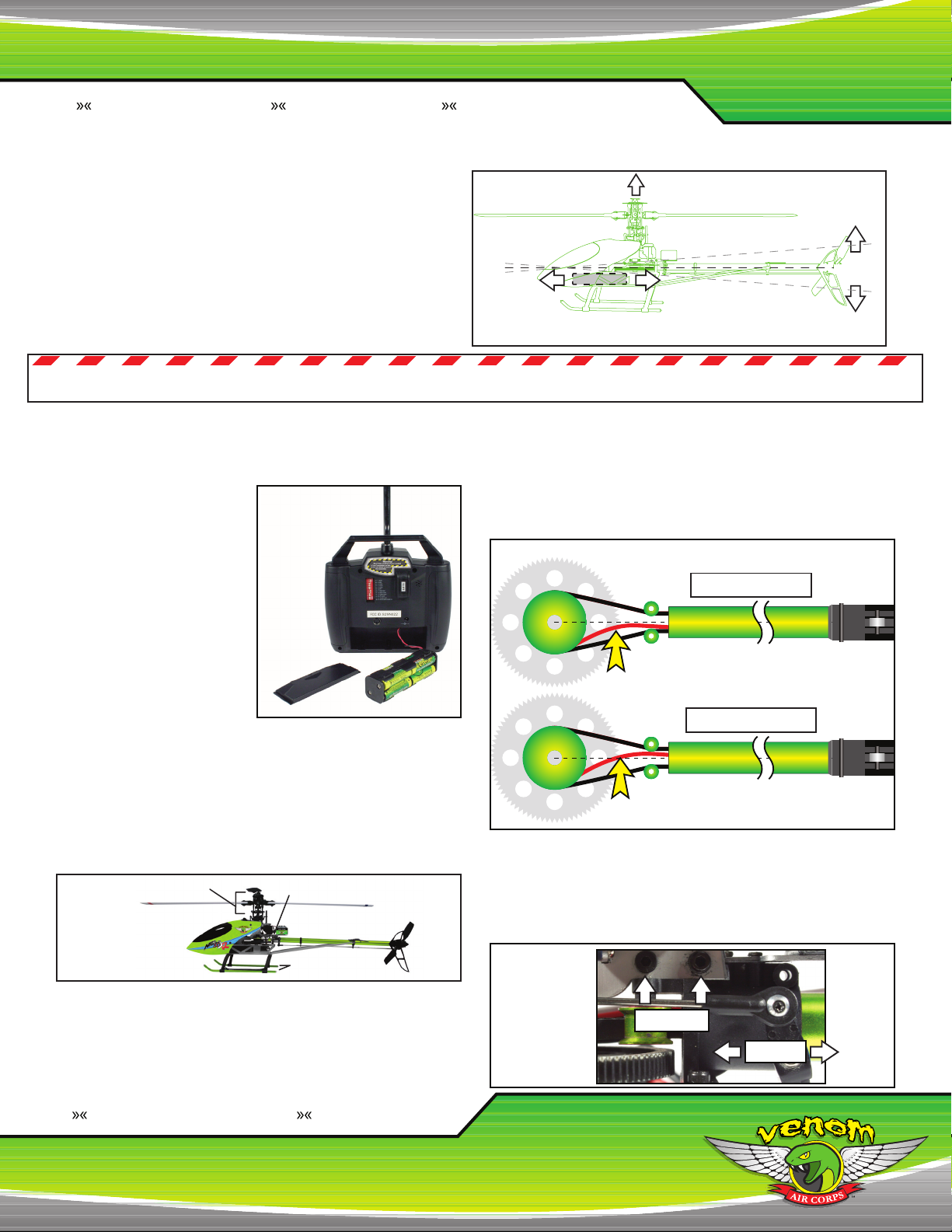
Throttle
Up
Throttle
Down
Pitch
Adjustment
Throttle
Adjustment
3D
Mode
Switch
23
14
Throttle
Up
Throttle
Down
Pitch
Adjustment
Throttle
Adjustment
3D
Mode
Switch
23
14
7
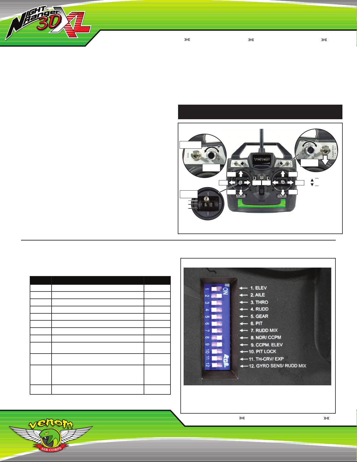
RADIO TRIM ADJUSTMENTS
(FINE TUNING):
MODE I - EUROPE & AUSTRALIA MODE II - NORTH AMERICA
ATTENTION: BEFORE CONNECTING THE BATTERY TO THE ESC, YOU MUST CONFIRM
THE FOLLOWING SETTINGS. MAKE SURE THE VNR 3DXL™ IS TURNED OFF DURING
THIS PROCESS!
1. The crystals on the radio and the receiver must match each other.
2. Antenna is screwed in and extended, batteries are fully charged and radio has been turned
on.
3. The throttle stick must be located in the throttle off position, otherwise serious damage to the
VNR 3DXL™ and personal injury may occur.
4. Make sure the Flight Mode switch is in the Normal Flight Mode.
If all of the above settings are confirmed, connect the battery to the ESC.
After the battery is connected, wait for the gyro to initialize (as described on page 5) before
flying. If the LED does not blink after the battery is connected, please check that you have
switched on the radio and that the battery is fully charged.
NOTE: If the throttle stick is not in the throttle off position when the battery is connected, the
gyro will still initialize but the throttle stick will not be active until it is returned to the throttle off
position. If the radio is working properly and the helicopter suddenly seems to shut off, that
condition is the result of a loss of signal or interference. The radio system has a built in fail safe
to prevent a run away helicopter. In the event of signal loss, the receiver is designed to stop its
activity and neutralize the helicopter to minimize damage to it and any property it may come in
contact with.
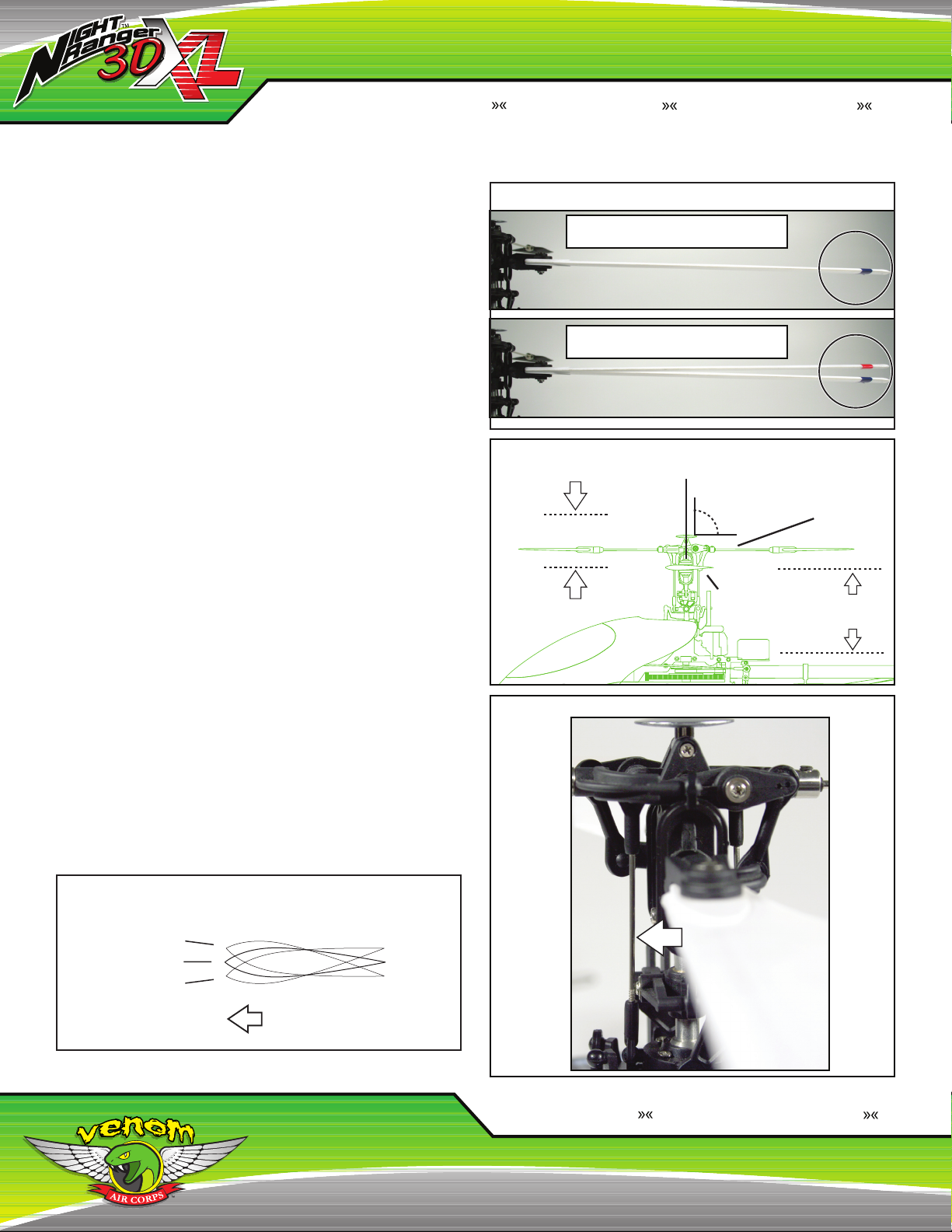
If the main rotor blades start rotating, and
the right control stick has not been pushed
forward, slowly adjust the radio trim 3until
they stop rotating.
If the main rotor blades start rotating, and
the left control stick has not been pushed
forward, slowly adjust the radio trim 2until
they stop rotating.
Make sure the swashplate is horizontal to the
ground. If the swashplate is not horizontal
from front to back, adjust the radio trim 2
until it is level to the ground (Fig. O). If the
swashplate is not horizontal from side to side,
adjust the radio trim 4until it is level to the
ground (Fig. O). Test the flight controls to
make sure they are operating properly and
the swashplate moves in the direction you
want to fly.
Make sure the swashplate is horizontal to the
ground. If the swashplate is not horizontal
from front to back, adjust the radio trim 3
until it is level to the ground (Fig. P). If the
swashplate is not horizontal from side to side,
adjust the radio trim 4until it is level to the
ground (Fig. P). Test the flight controls to
make sure they are operating properly and
the swashplate moves in the direction you
want to fly.
Push the right control stick slightly forward
to start the blade rotation. Keep your fingers,
eyes and other objects clear of the rotating
parts. When the main rotor blades start
rotating, the tail blades should start rotating
simultaneously.
Push the left control stick slightly forward to
start the blade rotation. Keep your fingers,
eyes and other objects clear of the rotating
parts. When the main rotor blades start
rotating, the tail blades should start rotating
simultaneously.
Slowly push the right control stick forward
to increase rotor speed. The VNR 3DXL™
may not take off vertically; it may go forward
or backwards, left or right. Continue to push
the right control stick forward and bring the
helicopter to a hovering height of waist high.
While hovering, use trim sliders 2 & 4to
fine tune the VNR 3DXL™ while hovering.
You may also find the helicopter’s nose
will swing to the left or right side when you
increase throttle. In this case, you need to
adjust the radio trim 1.
Slowly push the left control stick forward to
increase rotor speed. The VNR 3DXL™ may
not take off vertically; it may go forward or
backwards, left or right. Continue to push
the left control stick forward and bring the
helicopter to a hovering height of waist high.
While hovering use trim sliders 3 & 4to fine
tune the VNR 3DXL™ while hovering. You
may also find the helicopter’s nose will swing
to the left or right side when you increase
throttle. In this case, you need to adjust the
radio trim 1.
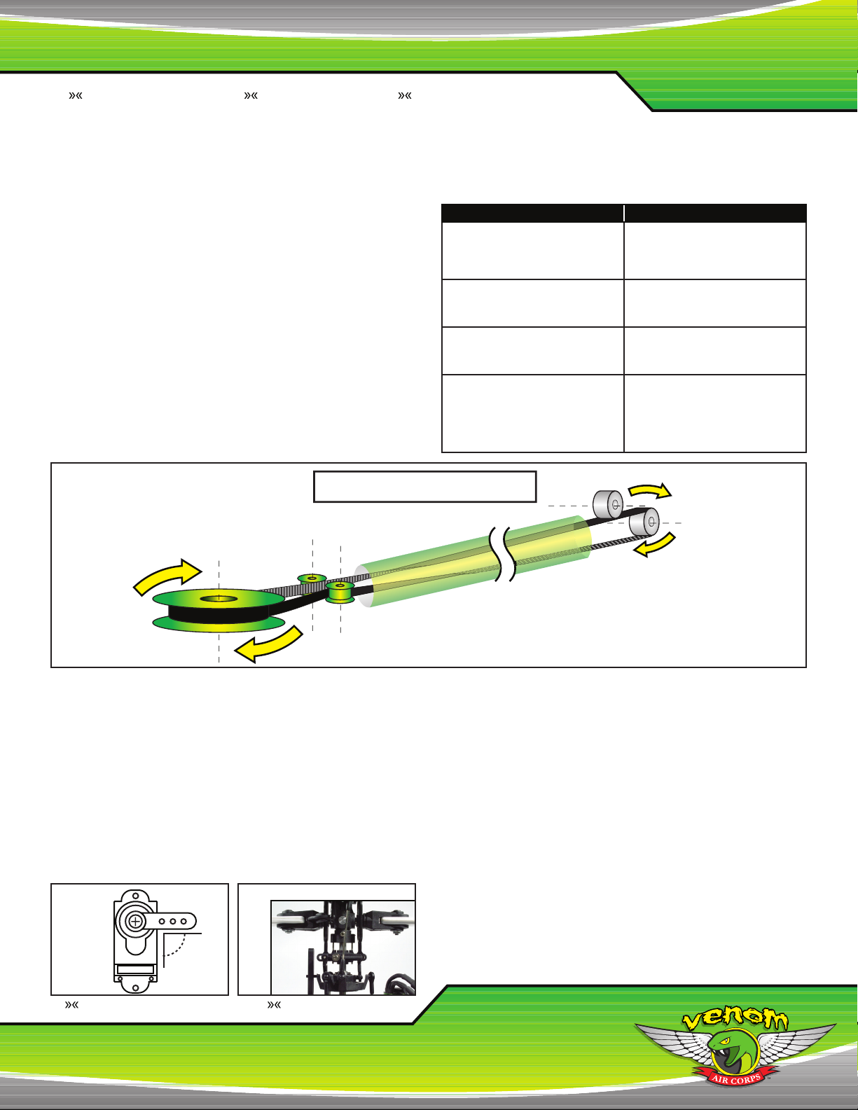
V. TUNING THE VNR 3DXL™
LESS RESPONSIVE:
- Reducing the throw of the Aileron and Elevator Cyclic will help make
the helicopter less sensitive. To do this move the pivot balls on the
servo arm to the inner most holes.
- With the head speed function selected (DIP switch #11) you can turn
down the head speed, which allows for a longer flight and makes
the helicopter less sensitive to control inputs. Do note that in windy
conditions, it is better to run a little bit higher head speed.
MORE RESPONSIVE:
- Increase the head speed, this will give you a faster response time,
but less flight time. Refer to the Pitch Range & Curve Adjustment
section on changing the head speed. Changing the head speed is
not only more effective than adding more cyclic throw, but has a
more positive response. Increasing the cyclic travel only binds the
head mechanics causing a loss of power and control.
NOTE: MODE I - EUROPE & AUSTRALIA
NOTE: MODE II - NORTH AMERICA
Fig. O
Fig. P