Owner's Instructions
Model No. : VG100
CAUTION: Read all instructions and warnings before operating!
SAVE THESE INSTRUCTIONS! READ ALL INSTRUCTIONS!
Vent-A-Garage System
WARNING: To avoid serious injury or death from electrical shock or fire.
1. DO NOT handle this system or try to plug it in when your hands are wet or when standing on a wet or damp surface.
2. RISK OF INJURY! Spinning Fan Blades -Do not connect to power until all covers and guards are in place.
3. This system MUST ALWAYS BE USED in accordance with all Electrical and safety codes and ordinances, including the most recent National Electric
Code (NEC) and with the Occupational Safety and Health Act (OSHA) Volume 1 on General Industry Standards and Interpretations.
4. ALWAYS disconnect the power before servicing or inspecting this system for any reason.
5. This system is ONLY FOR USE ON 110-120V circuits that is equipped with approved 3 conductor cord and 3-prong, grounded type plugs.
6. TO REDUCE THE RISK OF ELECTRICAL SHOCK, the power cord should only be connected to a properly grounded 3-prong outlet.
7. THIS SYSTEM IS FOR GARAGE USE ONLY! DO NOT intended to use in showers, saunas or in potentially wet locations.
8. DO NOT use in potentially dangerous locations, such as in flammable or explosive atmospheres.
9. KEEP OUT OF REACH OF CHILDREN.
INSTALLATION INSTRUCTIONS
STEP 1
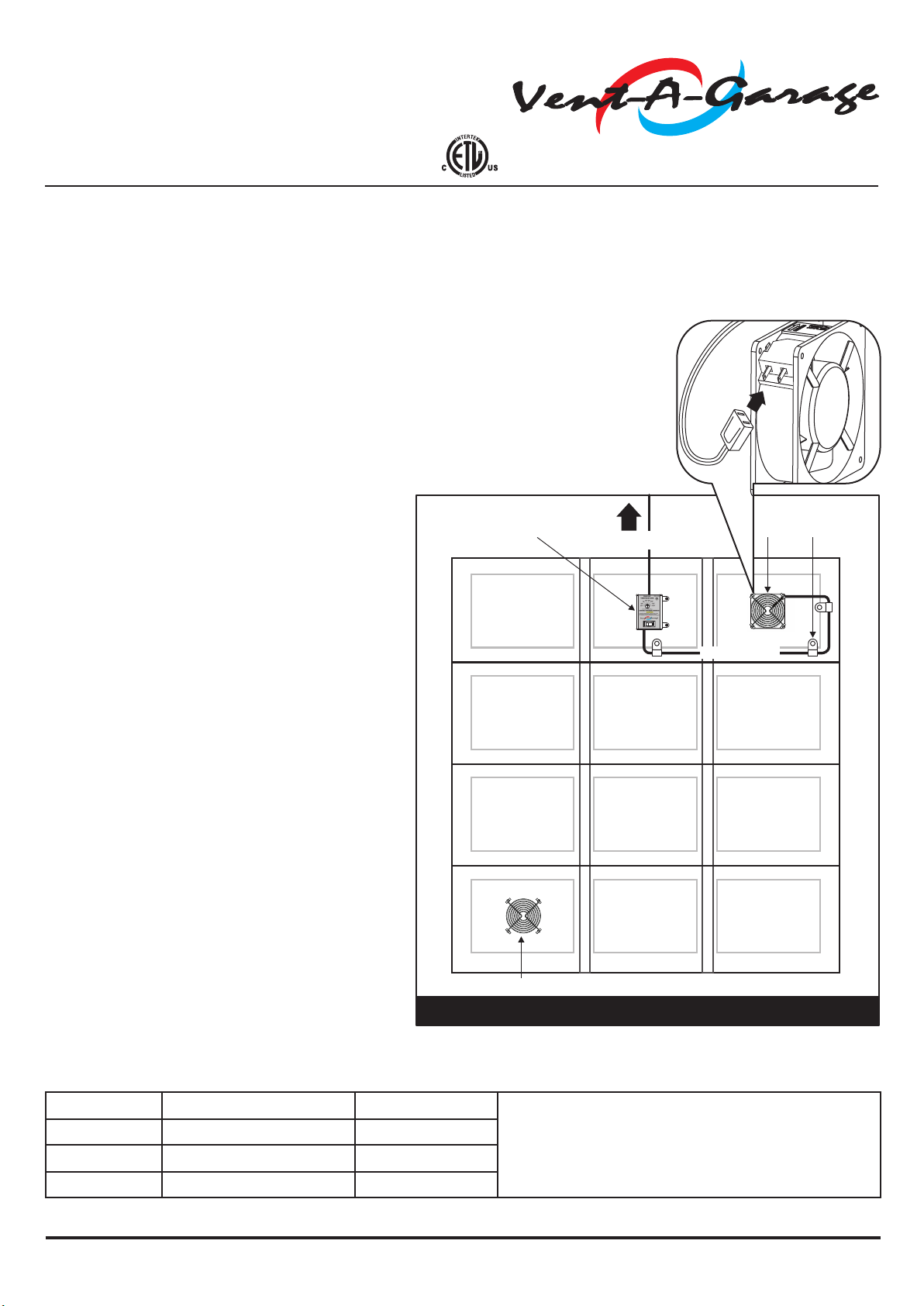
MARK AND CUT HOLES THRU DOOR - (Reference Fig.1)
1. Use the Template (Item #9) to draw the two 4 ½” vent hole locations on
the outside surface of the door. The 2 vent hole locations should be
positioned so that the distance to the edge of the door is the same for all.
The vent hole locations as shown in Fig.1, are conveniently positioned in
the center of the decorative panels of the illustrated door. However, your
door may have other panel arrangements or may be flat with no decorative
panels.
Caution! Before cutting the vent holes - Stand back and look at the marked
hole locations to make sure there are positioned as you like them from a
decorative point of view. Check the inside door surface behind the marked
vent holes to make sure that no braces or brackets will obstruct the cutting
of the marked holes.
2. Use the Template to mark four small holes adjacent to the upper 4 ½” hole
only. Fig 1. shows a typical layout of the hole locations for a typical garage
door. These marked holes should then be drilled to 3/16" Diameter. Be
careful to drill the holes as close to perpendicular to the door surface as
possible. (See inset illustration Fig. 1)
STEP 2
MOUNTING THE FANS - (Reference Fig 2A)
Use 4 Mounting Bolts (Item #7) to mount the Fan as shown in Fig. 2A.
Note! - Be sure to arrange the fan so that the air flow is directed toward the
outside of the garage. An arrow is marked on the side of the fan frame to
indicate the air flow direction.
Once the Fan is correctly in place, place the Finger Guard (Item #2) over the
mounting bolts. Use the Wing Nuts (Item #8) to secure the fan and finger
guards.
STEP 3
Install the Exterior Covers (Reference Fig. 2A & Fig.2B)
1. Place the Exhaust Cover (Item #3) over the upper vent hole cut in the door
with the Vent A Garage name oriented at the top. The circular lip on the
back side of the cover will fit inside the cut hole. Align the cover so that it is
parallel to the side of the door.
2. Fasten the cover to the door surface with 4 Self-Drilling Mounting Screws
A (Item #6). The screw will automatically pilot the holes since the tips are
self-drilling. It is recommended to hand tighten the screw until snug. DO
NOT OVER-TIGHTEN or the screw will strip the hole and lose grip.
3. Place the Intake Covers (Item #4) over the bottom vent holes and secure
in place. The same procedure is to be followed to fasten the Intake Cover
as described above using Self-Drilling Mounting Screws A (Item #6).
4. Finger Guard (Item #2) is provided to cover the inside of the intake vent
hole with Mounting Screw B( Item #21).
Fig. 2B
INTAKE COVER
GARAGE DOOR
FINGER GUARD
INSIDEOUTSIDE
Fig. 2A
EXHAUST COVER
GARAGE DOOR
FINGER GUARD
INSIDEOUTSIDE
MOUNTING BOLTS
AIR FLOW
Fig. 1
EXHAUST
INTAKE VENTS
TYPICAL GARAGE DOOR LAYOUT
4 1/2" DIA HOLES
3/16" HOLES
Winter Weather - If the Vent A Garage System is used in climates with cold winter weather, it may be desirable to cover the Intake Cover to block cold
air and wind from entering the garage. Intake Air Blocker (Item #5) can replace the Screen in the Intake Cover for this purpose. (Fig 2C)
Save the Screen in a convenient location so it can be reinstalled in the spring season.