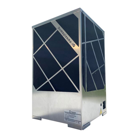
Venture Industries LAUTUS User manual

INSTRUKCJA OBSŁUGI I MONTAŻU NR / OPERATION AND MONTAGE MANUAL NO.: LAUTUS/2020/V2
(obowiązuje od / valid since: 1.10.2020)
(PL) Venture Industries Sp. z o.o. nie bierze odpowiedzialności za szkody powstałe w wyniku nieprzestrzegania zaleceń zawartych w niniejszym dokumencie oraz
zastrzega sobie prawo do jego zmian i modyfikacji bez konieczności powiadamiania użytkownika.
(EN) Venture Industries Sp. z o.o. is not responsible for any damage caused by improper use of the fan and reserves the right to modify this document without
informing the user.
INSTRUKCJA OBSŁUGI
OCZYSZCZACZA POWIETRZA LAUTUS
OPERATION MANUAL
OF AIR PURIFIER LAUTUS

LAUTUS/2020/V2
2/20 tel. +48 (22) 751 95 50 www.venture.pl fax. +48 (22) 751 22 59
tel. (22) 751 95 50 www.venture.pl fax. (22) 751 22 59
Spis treści / Table of contents
JĘZYK POLSKI
1. DANE OGÓLNE ..........................................................................................................................................................3
1.1 Informacje o urządzeniu.......................................................................................................................................3
1.2 Ogólne zagrożenia i wytyczne ..............................................................................................................................3
2. TRANSPORT I SKŁADOWANIE....................................................................................................................................4
3. MONTAŻ ...................................................................................................................................................................4
3.1 Informacje ogólne ................................................................................................................................................4
3.2 Informacje montażowe ........................................................................................................................................4
3.3 Podłączenie elektryczne .......................................................................................................................................5
4. EKSPLOATACJA .........................................................................................................................................................6
4.1 Wytyczne użytkowania.........................................................................................................................................6
4.2 Sygnalizacja stanów pracy urządzenia..................................................................................................................6
4.3 Sygnalizacja bocznym oświetleniem LED .............................................................................................................6
4.4 Opis funkcjonowania urządzenia..........................................................................................................................7
5. KONSERWACJA, OKRESOWE PRZEGLĄDY ................................................................................................................7
5.1 Wytyczne konserwacji ..........................................................................................................................................7
5.2 Przegląd i konserwacja urządzenia.......................................................................................................................7
5.3 Zalecany czas obsługi komponentów urządzenia ................................................................................................8
6. NAPRAWY, GWARANCJA..........................................................................................................................................8
7. DEMONTAŻ I UTYLIZACJA.........................................................................................................................................8
ZAŁĄCZNIK - A (Oznaczenia wyrobu) ................................................................................................................................9
ZAŁĄCZNIK - B (Deklaracja producenta) .........................................................................................................................10
ZAŁĄCZNIK - C (Schemat ideowy oczyszczacza powietrza).............................................................................................11
ENGLISH (Translation)
1. GENERAL INFORMATION.........................................................................................................................................12
1.1 Information about device...................................................................................................................................12
1.2 General risk and guidelines ................................................................................................................................12
2. TRANSPORT AND STORAGE.....................................................................................................................................13
3. INSTALLATION .........................................................................................................................................................13
3.1 General information ...........................................................................................................................................13
3.2 Assembly information ........................................................................................................................................13
3.3 Electrical connection guidelines.........................................................................................................................14
4. USE...........................................................................................................................................................................15
4.1 Use guidelines.....................................................................................................................................................15
4.2 Signaling of device operation states ..................................................................................................................15
4.3 Signaling with side LED lighting ..........................................................................................................................15
4.4 Description of the device operation...................................................................................................................16
5. MAINTENANCE, PERIODIC INSPECTIONS ................................................................................................................16
5.1 Maintenance guidelines .....................................................................................................................................16
5.2 Inspection and maintenance of the device ........................................................................................................16
5.3 Recommended maintenance time for device components...............................................................................17
6. REPAIRS, WARRANTY ..............................................................................................................................................17
7. DISMANTLING AND RECYCLING ..............................................................................................................................17
ANNEX - A (Product designations) ..................................................................................................................................18
ANNEX - B (Declaration of manufacturer) ......................................................................................................................19
ANNEX - C (Schematic diagram of the air purifier).........................................................................................................20

LAUTUS/2020/V2
tel. +48 (22) 751 95 50 www.venture.pl fax. +48 (22) 751 22 59 3/20
JĘZYK POLSKI
WSTĘP
Niniejsza instrukcja dotyczy urządzenia wymienionego na stronie tytułowej. Stanowi ona źródło informacji niezbędnych do
zachowania bezpieczeństwa i prawidłowej jego eksploatacji. Należy uważnie przeczytać ją przed przystąpieniem do
jakiegokolwiek użytkowania urządzenia, stosować się do zawartych w niej wymogów oraz przechowywać w miejscu
umożliwiającym dostęp personelu obsługi i innych służb zakładowych. W razie jakichkolwiek wątpliwości co do użytkowania
wentylatora należy kontaktować się z producentem.
Po otrzymaniu wentylatora prosimy o sprawdzenie:
czy urządzenie jest zgodne z zamówieniem
czy dane na tabliczce znamionowej urządzenia odpowiadają parametrom żądanym.
czy urządzenie nie zostało uszkodzone podczas transportu (np. czy widnieją wgniecenia/pęknięcia).
W przypadku stwierdzenia jakichkolwiek nieprawidłowości prosimy o kontakt z punktem sprzedaży lub SERWISEM Venture Industries
Sp. z o.o.
1. DANE OGÓLNE
1.1 Informacje o urządzeniu
Urządzenie przeznaczone jest do użytku domowego lub zastosowania w środowisku przemysłowym. Dozwolone jest użytkowanie oraz
obsługa urządzenia jedynie przez osoby dorosłe, które zapoznały się z niniejszą instrukcją lub zostały odpowiednio przeszkolone.
Urządzenie przeznaczone jest do transportu oraz oczyszczania powietrza z pyłów oraz mikroorganizmów. Zabroniony jest transport
mieszanin wybuchowych, ciał stałych, cieczy, substancji powodujących ścieranie, związków agresywnych chemicznie. Urządzenie jest
przeznaczone do użytku wewnętrznego w temp. otoczenia od 10°C do 40°C.
Maszynę należy chronić przed wpływem warunków atmosferycznych (np. śnieg, deszcz, nadmierne nasłonecznienie, wyładowania
atmosferyczne). Urządzenie nie jest przeznaczone do pracy na wolnym powietrzu. Otoczenie oczyszczacza nie może zawierać mieszanin
wybuchowych, substancji powodujących ścieranie, związków agresywnych chemicznie, substancji lepkich, cieczy, substancji o dużej
wilgotności.
Urządzenie nie może być narażone na promieniowanie (np. mikrofalowe, ultrafioletowe, laserowe, rentgenowskie).
Wirnik wentylatora wyważony jest zgodnie z klasą minimum G2.5 wg ISO 1940-1.
Opis konstrukcji urządzenia przedstawiony został w załączniku C.
Dodatkowe informacje nt. stosowania urządzenia umieszczone zostały na obudowie w formie oznaczeń. Więcej informacji przedstawiono
załączniku A.
1.2 Ogólne zagrożenia i wytyczne
W trakcie całego cyklu życia oczyszczacza należy zwrócić szczególną uwagę na poniżej przedstawione zagrożenia i wytyczne:
1.2.1 Elementy ruchome
Urządzenie posiada ruchome elementy (np. wirnik wentylatora), z którymi kontakt grozi poważnym kalectwem. Nie wolno
używać urządzenia, jeżeli nie została zamontowana pokrywa serwisowa, osłony oraz komplet filtrów.
Po odłączeniu od zasilania wirnik wentylatora może obracać się przez pewien czas. Pokrywę urządzenia można zdemontować
po całkowitym zatrzymaniu wirnika. W tym celu, przy zachowaniu szczególnej ostrożności, należy sprawdzić dłonią, czy na
wylocie z wentylatora występuje przepływ powietrza.
1.2.2 Siła ssania
Należy zwrócić szczególną uwagę, aby w pobliżu wlotu nie znajdowały się drobne elementy oraz złogi pyłu, gdyż ich zassanie może
spowodować szybkie zatkanie filtrów a nawet ich uszkodzenie.
1.2.3 Elementy wyrzucane
Przed pierwszym uruchomieniem oraz w przypadku otwarcia urządzenia (np. prace serwisowe) należy sprawdzić, czy we wnętrzu urządzenia
nie znajdują się obce elementy (np. narzędzia), które mogą uszkodzić urządzenie lub zostać wyrzucone z dużą prędkością na zewnątrz. Należy
regularnie sprawdzać stan osłon wylotu urządzenia.
1.2.4 Ostre krawędzie
•Na etapie produkcji ostre krawędzie obudowy urządzenia są poddawane łagodzeniu, jednakże może on posiadać krawędzie,
których dotknięcie może spowodować skaleczenie zwłaszcza wewnątrz urządzenia. Zalecane jest stosowanie rękawic
ochronnych podczas obsługi serwisowej urządzenia.
1.2.5 Hałas
Pracujące urządzenie wytwarza hałas. Wartość poziomu ciśnienia akustycznego generowanego przez urządzenie umieszczona
została na stronie www.venture.pl.
1.2.6 Materiały
W przypadku wystąpienia ognia lub transportowania nieodpowiedniego medium - elementy wentylatora mogą generować
opary niebezpieczne dla zdrowia.
1.2.7 Zagrożenia elektryczne
Przed przystąpieniem do jakichkolwiek prac przy wentylatorze (np. instalacja, konserwacja i przegląd, demontaż), urządzenie
należy całkowicie odłączyć od zasilania.
Urządzenia nie wolno stawiać na mokrej powierzchni, polewać go wodą ani dotykać mokrymi rękoma, ponieważ grozi to
porażeniem prądem.
W przypadku uszkodzenia przewodu zasilającego nie wolno używać urządzenia. Przed każdym podłączeniem do zasilania
należy sprawdzić czy przewód zasilający nie jest uszkodzony, a w przypadku uszkodzenia należy go wymienić.

LAUTUS/2020/V2
4/20 tel. +48 (22) 751 95 50 www.venture.pl fax. +48 (22) 751 22 59
tel. (22) 751 95 50 www.venture.pl fax. (22) 751 22 59
1.2.8 Użytkowanie
Nieprawidłowa instalacja i obsługa mogą prowadzić do uszkodzenia urządzenia oraz zaistnienia sytuacji niebezpiecznej. Obsługa urządzenia
może być prowadzona przez osoby zapoznane z instrukcją lub odpowiednio przeszkolone.
Niedozwolone są jakiekolwiek modyfikacje urządzenia. Skomplikowane prace konserwacyjne np. wymagające demontażu wirnika, filtrów
HEPA lub układów sterowania każdorazowo należy wykonywać w SERWISIE Venture Industries Sp. z o.o. lub poza serwisem - po uzyskaniu
zgody producenta, według dodatkowych wytycznych. Nieprawidłowy montaż może pogorszyć parametry pracy, doprowadzić do uszkodzenia
urządzenia, jak również do zaistnienia sytuacji niebezpiecznej.
W trakcie wykonywania prac nad urządzeniem (np. konserwacja, instalacja) otoczenie urządzenia należy zabezpieczyć przed dostępem osób
przypadkowych.
Z urządzenia należy korzystać zgodnie z jego przeznaczeniem. Nie wolno stawać, na urządzeniu ani kłaść na nim żadnych przedmiotów.
1.2.9 Odkładanie się pyłu
Należy przeciwdziałać gromadzeniu się kurzu, osadów na/w urządzeniu. Brud osadzający się na: osłonach powoduje obniżenie parametrów
pracy; wirniku - może spowodować nieprawidłowe wyważenie; obudowie- może utrudniać chłodzenie.
1.2.10 Występowanie atmosfery wybuchowej
Kontakt wentylatora z medium o charakterze wybuchowym spowoduje zapłon. Zabronione jest użytkowanie i
przechowywanie wentylatora w przypadku występowania atmosfery wybuchowej wewnątrz i/lub w otoczeniu urządzenia.
1.2.11 Promieniowanie UV
We wnętrzu urządzenia znajduje się lampa emitująca promieniowanie UV, które jest szkodliwe dla skóry i oczu. Zabronione
jest podłączanie urządzenia do zasilania, gdy wszystkie pokrywy urządzenia nie są zamknięte.
2. TRANSPORT I SKŁADOWANIE
Urządzenie należy transportować i przechowywać w oryginalnym opakowaniu, bez narażenia na nadmierne wstrząsy. Urządzenie musi
znajdować się w miejscu osłoniętym przed wpływem warunków atmosferycznych, w otoczeniu suchym i przewiewnym, wolnym od substancji
szkodliwych dla urządzenia - nie wolno transportować, przechowywać urządzenia w pomieszczeniach, gdzie gromadzone są nawozy sztuczne,
wapno chlorowane, kwasy, inne agresywne środki chemiczne. Należy zabezpieczyć urządzenie przed dostaniem się do środka ciał obcych.
W czasie transportu i przechowywania oczyszczacz powietrza należy chronić przed uszkodzeniami mechanicznymi, w tym przed zgnieceniem.
Podczas przenoszenia nie wolno gwałtownie opuszczać urządzenia.
Urządzenie należy podnosić za elementy obudowy i uchwyty do tego przeznaczone. Nie wolno podnosić urządzenia za przewody zasilające,
elementy wlotu, wylotu, czy przełączniki. Podczas podnoszenia urządzenie musi być stabilne.
Rys.1. Umiejscowienie uchwytów transportowych.
Nie wolno podchodzić pod przenoszony ładunek. W przypadku zerwania, upadające urządzenie może spowodować poważne
kalectwo lub śmierć.
Zalecamy, aby okres magazynowania urządzenia nie przekroczył jednego roku. Po długim składowaniu, przed instalacją należy sprawdzić stan
wentylatora (rozdział 5).
3. MONTAŻ
3.1. Informacje ogólne
Po rozpakowaniu urządzenia, przed pierwszym uruchomieniem, należy zdemontować elementy zabezpieczające na czas transportu.
Urządzenie po rozpakowaniu, zdjęciu elementów zabezpieczających oraz podłączeniu przewodu zasilania jest gotowe do użycia.
Uruchomienie oczyszczacza powietrza należy przeprowadzić z uwzględnieniem wytycznych określonych w rozdziale 1.2.
3.2 Informacje montażowe
Urządzenie należy ustawić na kółkach w pomieszczeniu lub przejściu w odpowiedniej odległości od ścian zgodnie z rysunkiem Rys. 2.
Oczyszczacza powietrza nie należy kłaść na boku ani w żadnej innej pozycji. Po zastosowaniu odpowiedniego króćca oraz kanału
wentylacyjnego, urządzenie może być wykorzystywane jako odciąg miejscowy (Rys.3).
Urządzenie należy ustawić na płaskim, sztywnym oraz suchym podłożu, które będzie w stanie przenieść jego ciężar.

LAUTUS/2020/V2
tel. +48 (22) 751 95 50 www.venture.pl fax. +48 (22) 751 22 59 5/20
Rys.2. Minimalna dopuszczalna odległość od ścian (widok na urządzenie z góry)
Rys.3. Schemat urządzenia zastosowanego jako odciągu miejscowego
Venture Industries Sp. z o.o. nie odpowiada za szkody powstałe w wyniku niewłaściwego montażu i użytkowania urządzenia.
3.3 Podłączenie elektryczne
W celu zapewnienia niezbędnego do pracy urządzenia zasilania należy podłączyć przewód zasilający do urządzenia (1), a następnie do źródła
zasilania (2) jak pokazano na rys. 4.
Rys. 4. Podłączenie zasilania

LAUTUS/2020/V2
6/20 tel. +48 (22) 751 95 50 www.venture.pl fax. +48 (22) 751 22 59
tel. (22) 751 95 50 www.venture.pl fax. (22) 751 22 59
4. EKSPLOATACJA
4.1 Wytyczne użytkowania
Należy upewnić się, że uruchomienie urządzenia nie stworzy zagrożenia dla bezpieczeństwa personelu i mienia. Należy stosować się do
wytycznych określonych w rozdziale 1.2.
Należy upewnić się, że wlot i wylot urządzenia nie są zasłonione, a minimalne odległości zapewnione jak określono w pkt. 3.2.
Należy upewnić się, że urządzenia posiada zasilanie.
Wcisnąć przycisk ON urządzenia (1), a następnie ustawić oczekiwany poziom wydajności urządzenia potencjometrem (2) jak pokazano
na rys. 5.
W cyklu pracy urządzenie początkowo włączy lampy UV-C na 5 min w celu oświetlenia i dezynfekcji wnętrza (boczne panele
zaczną świecić na niebiesko). Rozruch wentylatorów nastąpi po pierwszych 5 min od włączenia.
Rys. 5. Rozpoczęcie pracy urządzenia.
Pozycje 1, 2, 3 i 4 na nastawniku oznaczają kolejne pozycje pracy urządzenia. Pozycje oznaczone jako „0” są pozycjami pośrednimi
umożliwiającymi wyłączenie wentylatora bez potrzeby ponownego pełnego cyklu początkowego naświetlania, wentylator po przełączeniu na
jeden z czterech pozycji działania wentylatora, uruchomi się natychmiast, bez 5 minutowej zwłoki.
4.2 Sygnalizacja stanów pracy urządzenia
Dioda
Rodzaj sygnalizacji
Informacja
Działania
Dodatkowe informacje
Zielona
Światło ciągłe
Prawidłowa praca
urządzenia
-
-
Czerwona
Dioda migająca w cyklu:
1 s światło – 4 s STOP
Zabrudzenie filtra G4
Oczyścić filtr patrz 5.2.
Urządzenie będzie pracować przez 8h w trybie awaryjnym
(tj. na nastawie 1). Po upływie czasu wentylator wyłączy się.
Przy kolejnym włączeniu urządzenie wykona diagnostykę
zabrudzenia filtra.
Czerwona
Dioda migająca w cyklu:
1 s światło – 1 s STOP
Błąd lampy UV-C
Serwis
Wentylator wyłączy się
Czerwona
Światło ciągłe
Rozszczelnienie urządzenia
Serwis
Wentylator wyłączy się
4.3 Sygnalizacja bocznym oświetleniem LED
Urządzenie zostało wyposażone w boczne diody LED koloru niebieskiego (rys.6.) Informujące o aktualnym stanie lampy UV-C. Diody świecą się
światłem ciągłym równolegle z lampą UV-C.
Rys. 6. Oświetlenie boczne LED
Nastawa
Wydajność
0
0 m3/h (pauza)
1
120 m3/h
2
240 m3/h
3
320 m3/h
4
410 m3/h

LAUTUS/2020/V2
tel. +48 (22) 751 95 50 www.venture.pl fax. +48 (22) 751 22 59 7/20
4.4 Opis funkcjonowania urządzenia
Po podłączeniu urządzenia do zasilania i włączenia przyciskiem ON urządzenie uruchomi się. Przez pierwsze 5 min następuje naświetlenie
lampą UV-C wnętrza urządzenia co jest sygnalizowane poprzez zapalone panele LED na bokach obudowy. Po 5 min nastąpi włączenie
wentylatora. Lampa UV –C pracuje w interwałach od chwili włączenia urządzenia w celu minimalizacji zużycia energii. Od włączenia lampa
działa przez godzinę, a następnie się wyłącza na godzinę pracując w zamkniętym cyklu do chwili wyłączenia urządzenia przyciskiem OFF lub
odłączenia zasilania. W przypadku nieprawidłowego funkcjonowania urządzenia patrz pkt. 4.2. w celu diagnostyki oraz podjęcia działań.
5. KONSERWACJA, OKRESOWE PRZEGLĄDY
5.1 Wytyczne konserwacji
Podczas przeprowadzania konserwacji oraz przeglądów należy zachować zasady bezpieczeństwa określone w punkcie 1.2
Urządzenie należy poddawać regularnym okresowym przeglądom i konserwacji (punkt 5.2).
Do czyszczenia konstrukcji należy użyć lekko zwilżonej szmatki, zabrania się używania detergentów i cieczy pod ciśnieniem oraz narzędzi
mogących porysować powierzchnię urządzenia.
Należy regularnie sprawdzać poziom zanieczyszczenia filtra wstępnego. W przypadku zabrudzenia należy wyczyścić filtr jak pokazano w 5.2.
Oczyszczacz powietrza należy uruchomić minimum raz w miesiącu na nastawie 4 na minimum 15 min celem auto-diagnostyki urządzenia
Należy zapewnić, że żadne ciała obce (np. elementy montażowe, narzędzia) nie znajdują się wewnątrz komory wirnika, urządzenie jest suche i
odpowiednio zabezpieczone po zakończeniu konserwacji, przeglądu czy wymiany filtrów. Po zakończeniu czyszczenia urządzenia należy
uruchomić je z maksymalnymi obrotami na czas minimum 30 minut.
Podczas przeglądów należy zwrócić szczególną uwagę na następujące zagrożenia:
Osad i
zanieczyszczenie
urządzenia
Należy przeciwdziałać gromadzeniu się kurzu, osadów na urządzeniu. Brud osadzający się na: osłonach powoduje
obniżenie parametrów pracy; obudowie wentylatora - może utrudniać chłodzenie. W obszarze gorących powierzchni -
może ulec zapaleniu.
Korozja
Korozja może prowadzić do mechanicznego uszkodzenia wentylatora. Nie wolno używać wentylatora w przypadku
występowania korozji.
Drgania
Nadmierne drgania mogą spowodować mechaniczne uszkodzenie wentylatora lub całej konstrukcji. Wzrost drgań może
świadczyć o utracie wyważenia wirnika. W przypadku wzrostu wartości drgań należy ustalić ich przyczynę i poddać
urządzenie naprawie.
5.2 Przegląd i konserwacja urządzenia
Odstępy pomiędzy rutynowymi badaniami i przeglądami powinny być określone przez użytkownika na podstawie obserwacji urządzenia i tak
dobrane, aby uwzględniały określone warunki pracy i działania. Jednocześnie kontrola nie może być rzadsza niż przedstawiona w punkcie 5.3.
W przypadku wykrycia nieprawidłowości, urządzenie należy wycofać z użytku i poddać naprawie / czyszczeniu (w przypadku stwierdzenia
zabrudzenia).
Osoby obsługujące urządzenie muszą zostać zaznajomione z warunkami pracy wentylatora i w razie pracy odbiegającej od normy powinny
wyłączyć urządzenie w celu poddania go inspekcji.
Szczegółowe informacje dotyczące zastosowanych komponentów oraz momentu ich dokręcenia dostępne są na zapytanie.
Zalecana codzienna kontrola lub w przypadku uruchamiania urządzenia:
urządzenie nie jest uszkodzone, działa poprawnie oraz jest stabilne,
wszystkie pokrywy i osłony są prawidłowo zamontowane,
urządzenie jest szczelne,
nie występują wycieki, dym z silnika,
urządzenie nie emituje nietypowych hałasów oraz nie nagrzewa się nadmiernie,
urządzenie jest czyste (ogólna kontrola), filtry nie są zapchane,
przewody elektryczne nie są uszkodzone,
osłony są czyste i nie zostały uszkodzone,
nie świecą się lampki informujące o awarii.
Czyszczenie zabrudzonego filtra wstępnego:
W przypadku oceny przez użytkownika, że filtr jest zabrudzony, lub w przypadku sygnalizacji przez system wykrywania zabrudzeń urządzenie
należy poddać czyszczeniu w następujący sposób:
1) Odkręcić śruby pokazane na rys. 7.
2) Wyciągnąć ramkę zewnętrzną urządzenia.
3) Wysunąć filtr z zewnątrz
4) W zależności od potrzeb –przetrzeć ściereczką lub odkurzyć odkurzaczem z miękką końcówką.
Do czyszczenia urządzenia zabrania się korzystania z wody – może to prowadzić do trwałego uszkodzenia
5) Ponownie wsunąć filtr do urządzenia.
6) Nałożyć ramkę i przykręcić śruby

LAUTUS/2020/V2
8/20 tel. +48 (22) 751 95 50 www.venture.pl fax. +48 (22) 751 22 59
tel. (22) 751 95 50 www.venture.pl fax. (22) 751 22 59
Rys. 7. Śruby do odkręcenia
5.3 Zalecany czas obsługi komponentów urządzenia
Czyszczenie filtra wstępnego G4 – co 2000 rbh lub zgodnie z sygnalizacją urządzenia o zabrudzeniu filtra (opis sygnalizacji w pkt 4.2) po
uprzednim sprawdzeniu stanu filtra i przyczyny awarii.
Wymiana filtra wstępnego G4 – co 10 000 rbh lub wcześniej w przypadku pracy w warunkach bardzo zanieczyszczonego powietrza.
Wymiana Filtra pośredniego H13 – co 20 000 rbh - wymiana powinna być połączona z wymiana filtra dokładnego H14 i lampy UV-C, by
zachować pełną szczelność i jakość filtracji w komorze pomiędzy filtrami.
Wymiana filtra dokładnego H14 –co 20 000 rbh - wymiana powinna być połączona z wymiana filtra pośredniego H13 i lampy UV-C, by
zachować pełną szczelność i jakość filtracji w komorze pomiędzy filtrami lub zgodnie z sygnalizacją urządzenia o rozszczelnieniu filtra (opis
sygnalizacji w pkt 4.2) po uprzednim sprawdzeniu stanu filtra i przyczyny awarii.
Lampa UV-C - co 20 000 rbh urządzenia - wymiana powinna być połączona z wymiana filtrów pośredniego H13 i filtra dokładnego H14, by
zachować pełną szczelność i jakość filtracji w komorze pomiędzy filtrami lub zgodnie z sygnalizacją urządzenia o awarii lampy (opis
sygnalizacji w pkt 4.2) po uprzednim sprawdzeniu stanu lamy i przyczyny awarii.
Obsługa filtra G4 może być w pełni realizowana przez użytkownika urządzenia.
Do wymiany komponentów takich jak: Filtr H13, filtr H14, Lampa UV-C należy wezwać serwis VENTURE INDUSTRIES Sp. z o.o.
NIE NALEŻY STOSOWAĆ ZAMIENNIKÓW Z INNYCH ŹRÓDEŁ
Zalecamy przeprowadzanie rutynowych kontroli przez serwis VENTURE INDUSTRIES Sp. z o.o.
6. NAPRAWY, GWARANCJA
Należy stosować jedynie oryginalne części zamienne. Naprawy wentylatorów mogą być wykonywane jedynie w serwisie Venture Industries Sp.
z o.o. lub poza serwisem –po uzyskaniu zgody producenta. Warunki gwarancji określone są w karcie gwarancyjnej urządzenia.
Elementy eksploatacyjne takie jak filtry oraz lampa UV-C nie podlegają gwarancji ze względu na naturalne zużycie
7. DEMONTAŻ I UTYLIZACJA
Urządzenie należy odłączyć od zasilania, a następnie zdemontować przy zachowaniu wytycznych określonych w rozdziale 1. Prosimy o
zdawanie wszystkich pozostałych elementów opakowania w odpowiednich kontenerach do recyklingu, a także o dostarczanie wymienionych
urządzeń do najbliższej firmy zajmującej się utylizacją odpadów.

LAUTUS/2020/V2
tel. +48 (22) 751 95 50 www.venture.pl fax. +48 (22) 751 22 59 9/20
ZAŁĄCZNIK - A (Oznaczenia wyrobu)
[1] –nazwa wyrobu
[2] –liczba faz
[3] –napięcie znamionowe
[4] –częstotliwość znamionowa
[5] –moc urządzenia
[6] –prąd urządzenia
[7] –temperatura przetłaczanego
medium/otoczenia
[8] –masa urządzenia
[9] –wydajność znamionowa
[10] –poziom ciśnienia akustycznego
[11] –klasy filtrów (dla III stopni filtracji)
[12] –żywotność lampy UV
[13] –data wyprodukowania urządzenia
[14] –numer seryjny urządzenia
[15] –numer artykułu urządzenia
Dodatkowe informacje umieszczone na urządzeniu:
- oznaczenia dotyczące bezpiecznego użytkowania urządzenia

LAUTUS/2020/V2
10/20 tel. +48 (22) 751 95 50 www.venture.pl fax. +48 (22) 751 22 59
tel. (22) 751 95 50 www.venture.pl fax. (22) 751 22 59
ZAŁĄCZNIK - B (Deklaracja producenta)

LAUTUS/2020/V2
tel. +48 (22) 751 95 50 www.venture.pl fax. +48 (22) 751 22 59
11/20
ZAŁĄCZNIK - C (Schemat ideowy oczyszczacza powietrza)
Ogólny opis urządzenia (uproszczony)
A –wlot,
B –wylot,
C –koła jezdne,
D –uchwyty transportowe,
E –hamulec,
F –diody boczne LED,
G –panel sterowania
Opis elementów urządzenia (uproszczony)
1 –pokrywa wlotu z siatką
miedzianą,
2 –filtr wstępny G4
3 –filtr pośredni H13
4 –przegroda miedziana
5 –lampa UV-C z oprawą
6 –filtr dokładny H14
7 –wirniko-silnik
Elementy obudowy wentylatora wykonane zostały z blachy aluminiowej malowanej oraz mocowanej do profili aluminiowych scalonych
łącznikami wykonanymi z tworzywa sztucznego. Wirnik (7) wykonany został z tworzywa sztucznego. Siatka mocowana w elemencie (1) oraz
element (4) zostały wykonane z miedzi. Ponadto wewnątrz urządzenia w komorze wirniko-silnika znajduje się wygłuszenie dźwiękochłonne
wykonane z izolacji technicznej.
Pełny spis elementów i materiałów zastosowanych w wentylatorze może zostać udostępniony na uzasadnione zapytanie.
Wykaz części zamiennych
Nazwa części
Numer artykułu Venture Industries
Lautus 50
Lautus 100
Filtr wstępny G4
91020328
91020329
Filtr pośredni H13*
91020324
91020325
Lampa UV-C*
91041191
Wirniko-silnik Lautus*
45026780-07
Koło
70520020-01
Koło z hamulcem
70520020-02
*Wymiana tych elementów na własną rękę powoduje ingerencje w budowę urządzenia, a co za tym idzie utratę gwarancji.

LAUTUS/2020/V2
12/20 tel. +48 (22) 751 95 50 www.venture.pl fax. +48 (22) 751 22 59
tel. (22) 751 95 50 www.venture.pl fax. (22) 751 22 59
ENGLISH (Translation)
INTRODUCTION
This manual covers fans in standard version, listed on the title page (In the case of the fan special version the manual may be
different from this document). It is source of information necessary for safe and proper use. Read this manual carefully before
any use of the device, comply with its requirements and keep it in place with easy access for users and service. If case of any
doubts about use of the fan, please contact with manufacturer.
After receiving the device - check:
whether the device is in compliance with order,
whether the data on the rating plate are the same as desidered (voltage, frequency, etc.)
whether fan was not damaged during transport (e.g. there are no dents/cracks, impeller rotates freely)
In case of any irregularities, contact with your dealer or Venture Industries Sp. z o.o. service.
1. GENERAL INFORMATION
1.1 Information about device
The device is intended for domestic use or use in an industrial environment. It is allowed to use and operate the device only by adults who
have read this manual or have been properly trained.
The device is designed to transport and purify the air from dust and microorganisms. It is forbidden to transport explosive gases, solids,
liquids, abrasive substances, and chemically aggressive compounds. The device is designed for indoor use at an ambient temperature of 10 ° C
to 40 ° C
The purifier should be protected against the influence of weather conditions (eg snow, rain, excessive sunlight, lightning). The device is not
intended for outdoor use. The camera environment cannot contain explosive mixtures, abrasive substances, chemically aggressive substances,
viscous substances, liquids, substances with high humidity. The device must not be exposed to radiation (e.g. microwave, ultraviolet, laser,
x-ray).
• A description of the structure of the device is presented in Annex C.
• Additional information on the use of the device is provided on the housing in the form of stickers. More information is provided in Annex A.
1.2 General risk and guidelines
During entire air purifier life cycle pay particular attention to the risk and guidelines presented below:
1.2.1 Mechanical risk and guidelines
The device has moving parts (eg fan impeller), contact with which may cause serious injury. Do not use the device if the
service cover is open and a set of filters have not been closed.
After being disconnected from the power supply, the fan wheel may rotate for some time. The cover of the device can be
removed after the rotor has stopped completely. To do this, with extreme caution, check with your hand that there is air flow
at the outlet of the fan.
1.2.2 Suction power
Pay particular attention to the fact that there are no small elements or dust deposits near the inlet, as their suction may cause quick clogging
of the filters and even their damage.
1.2.3 Thrown items
Before the first start-up and after the device was opened (eg service work), check that the inside of the device does not contain foreign
elements (eg tools) that could damage the device or be thrown outside. Regularly check the condition of the appliance outlet covers.
1.2.4 Sharp edges
At the production stage, sharp edges of the device casing are softened, however, it may have edges, touching which may
cause injury, especially inside the device. It is recommended to wear protective gloves when servicing the equipment.
1.2.5 Risk and guidelines related with noise
The operating device produces noise. The value of the sound pressure level generated by the device is available at
www.venture.pl.
1.2.6 Materials
In the event of fire or transport of an inappropriate medium - fan elements may generate vapours hazardous to health.
1.2.7 Risk and guidelines related with electricity
Do not perform any work on the device (eg. installation, use, maintenance and inspection, dissambly) with exposed parts that
may be under voltage. Capacitor (only in units with single phase supply) has accumulated charge even after disconnecting the
unit. The appropriate steps should be made to prevent from electric shock. Protect from getting access to the electric elements
by unauthorized person.
Do not put the device on a wet surface, spray it with water or touch it with wet hands, as this may result in electric shock.
Do not use the device if the power cord is damaged. Before connecting to the power supply, check that the power cord is not damaged, and if
damaged, replace it.
1.2.8 Maintenance
Incorrect installation and operation may lead to damage to the device and a dangerous situation. The operation of the device may be carried
out by persons acquainted with the manual or properly trained.
Any modifications to the device are not allowed. Complicated maintenance works, e.g. requiring disassembly of the rotor, HEPA filters or
control systems, should be performed each time by the SERVICE of Venture Industries Sp. z o.o. or outside the service - after obtaining the
manufacturer's consent, according to additional guidelines. Incorrect assembly may deteriorate the operating parameters, damage the device,
and lead to a hazardous situation.

LAUTUS/2020/V2
tel. +48 (22) 751 95 50 www.venture.pl fax. +48 (22) 751 22 59
13/20
While working on the device (eg maintenance, installation), the surroundings of the device must be protected against access by unauthorized
persons.
Use the device in accordance with its intended purpose. Do not stand, sit on the device, or place any objects on it.
1.2.9 Dust deposition
Prevent the accumulation of dust and sediments on / in the device. Dirt depositing on: the covers reduces the operating parameters; rotor -
may cause improper balance; housing - may hinder cooling.
1.2.10 The presence of an explosive atmosphere
Contact of the fan with an explosive medium will cause ignition. It is forbidden to use and store the fan in the presence of an
explosive atmosphere inside and / or around the device.
1.2.11 UV radiation
There is a lamp inside the device which emits UV radiation which is harmful to the skin and eyes. It is forbidden to connect
the device to the power supply if all the device covers are not closed.
2. TRANSPORT AND STORAGE
The device should be transported and stored in its original packaging, without excessive shocks. The device must be located in a place
protected against the influence of weather conditions, in a dry and airy environment, free from substances harmful to the device - it must not
be transported or stored in rooms where artificial fertilizers, chlorinated lime, acids, and other aggressive chemicals are stored. Protect the
device against foreign bodies getting inside.
During transport and storage, the air purifier should be protected against mechanical damage, including crushing. When moving, do not
abruptly leave the device.
The device should be lifted by housing elements and handles intended for this purpose. Do not lift the equipment by the power cords, intake,
exhaust, or switches. The machine must be stable during lifting.
Fig. 1 Transport lugs
Fig. 1 Transport lugs
Do not approach under the load being carried. In case of rupture, falling equipment can cause serious injury or death.
We recommend that the storage period of the device should not exceed one year. After long storage, the condition of the fan must be
checked prior to installation (chapter 5).
3. INSTALLATION
3.1. General information
After unpacking the device, disassemble the safety elements for transport before the first start-up. After unpacking, removing the protective
elements and connecting the power cord, the device is ready for use
The air purifier must be started up in accordance with the guidelines set out in chapter 1.2.
3.2. Assembly information
The device should be placed on wheels in the room or in a walkway at the appropriate distance from the walls as shown in Fig. 2. The air
purifier should not be placed on its side or in any other position. After using an appropriate stub and a ventilation duct, the device can be used
as a local exhaust (Fig. 3).
Place the device on a flat, rigid and dry surface that can support its weight.

LAUTUS/2020/V2
14/20 tel. +48 (22) 751 95 50 www.venture.pl fax. +48 (22) 751 22 59
tel. (22) 751 95 50 www.venture.pl fax. (22) 751 22 59
Fig.2. Minimum allowed distance from walls (top view of the device)
Fig. 3. Using the device as a local extraction
Venture Industries Sp. z o.o. is not responsible for damages caused by improper installation and use of the device.
3.3 Electrical connection guidelines
In order to provide the power supply necessary for the operation of the device, connect the power cord to the device (1), and then to the
power source (2) as shown in fig. 4.
Fig. 4. Connecting the power supply

LAUTUS/2020/V2
tel. +48 (22) 751 95 50 www.venture.pl fax. +48 (22) 751 22 59
15/20
4. USE
4.1 Use guidelines
Make sure that starting the device does not pose a threat to the safety of personnel and property. Follow the guidelines in chapter 1.2.
Make sure that the inlet and outlet of the device are not obstructed, and the minimum distances as specified in point 3.2.
Make sure the equipment is powered.
Press the ON button of the device (1) and then set the expected level of performance of the device with the potentiometer (2) as shown in
fig. 5.
In the working cycle, the device will initially turn on the UV-C lamps for 5 minutes to illuminate and disinfect the interior (the
side panels will turn blue). The fans will start up after the first 5 minutes of switching on.
Fig. 5. Device start-up.
Positions 1, 2, 3 and 4 on the potentiometer inform about the next operating positions of the device. The positions marked with "0" are
intermediate positions they allow the fan to be turned off without the need for re-complete the initial exposure cycle. After switching to one of
the four working fan positions, the fan will start immediately, without a 5-minute delay.
4.2 Signaling of device operation states
Diode
Type of signaling
Information
To do
Additional information
Green
Continuous light
Correct operation of the device
-
-
Red
LED flashing in cycle:
1 s light - 4 s STOP
G4 filter is dirty
Clean the filter, see 5.2.
The device will run for 8 hours in emergency mode ( on
setting 1). After the time has elapsed, the fan will turn off.
The next time the device is turned on, it will diagnose the
filter contamination.
Red
LED flashing in cycle:
1 s light - 1 s STOP
UV-C lamp error
Call service
The fan will turn off
Red
Continuous light
Unsealing the device
Call service
The fan will turn off
4.3 Signaling with side LED lighting
The device is equipped with side blue LEDs (fig. 6.) informing about the current state of the UV-C lamp. The LEDs light up simultaneously with
the UV-C lamp.
Fig. 6. LED side lighting
Setting
Airflow
0
0 m3/h (pause)
1
120 m3/h
2
240 m3/h
3
320 m3/h
4
410 m3/h

LAUTUS/2020/V2
16/20 tel. +48 (22) 751 95 50 www.venture.pl fax. +48 (22) 751 22 59
tel. (22) 751 95 50 www.venture.pl fax. (22) 751 22 59
4.4 Description of the device operation
After connecting the device to the power supply and turning it on with the ON button, the device will start up. For the first 5 minutes the
interior of the device is irradiated with a UV-C lamp, this is indicated by lit LED panels on the sides of the housing. After 5 minutes, the fan will
turn on. The UV-C lamp works in intervals from the moment the device is turned on in order to minimize energy consumption. The lamp works
since the switch on for an hour and then turns off for an hour and tThis cycle of work continues until the device is turned off with the OFF
button or the power supply is disconnected. In case of device malfunction see pt. 4.2. for diagnosis and take corrective actions.
5. MAINTENANCE, PERIODIC INSPECTIONS
5.1 Maintenance guidelines
During maintenance and inspection, the safety rules specified in section 1.2 must be complied
The device must be subjected to periodic inspections and maintenance (point 5.2).
To clean the structure, use a slightly damp cloth, do not use detergents, pressurized liquids or tools that can scratch the surface of the device.
Regularly check the contamination level of the pre-filter. If dirty, clean the filter as shown in 5.2.
The air purifier should be started at least once a month on setting 4 for a minimum of 15 minutes for device self-diagnostics
It must be ensured that no foreign bodies (e.g. assembly elements, tools) are inside the rotor chamber, the device is dry and properly secured
after completion of maintenance, inspection or filter replacement. After cleaning the device, run it at maximum speed for at least 30 minutes.
• During inspections, pay particular attention to the following hazards:
Dust and
contamination of
the device
Prevent the accumulation of dust and sediments on the device. Dirt depositing on: the covers reduces the operating
parameters; fan housing - may impede cooling. In the area of hot surfaces - it may catch fire.
Corrosion
Corrosion can lead to mechanical damage to the fan. The fan must not be used in the presence of corrosion.
Vibrations
Excessive vibrations can cause mechanical damage to the fan or the entire structure. Increased vibrations may indicate
the rotor is out of balance. In the event of an increase of vibration value, determine the cause and remove it, or contact
service.
5.2 Inspection and maintenance of the device
Intervals between routine examinations and inspections should be determined by the user based on observation of the equipment and
performed to take account of specific operating conditions. At the same time, the check cannot be less than that shown in item 5.3.
If any irregularities are detected, the device should be taken out of use and repaired / cleaned (in case of dirt). Appendix B shows examples of
reasons for the failure of the device.
Persons operating the device must be familiarized with the conditions of the fan's operation and, in the event of abnormal operation, they
should turn the device off and be inspected.
• Detailed information on the components used and their tightening torque are available on request.
Recommended daily checks or when starting the device:
all covers are properly installed,
the device is tight,
there are no leaks, smoke from the motor,
the device does not emit unusual noises and does not heat up excessively,
the device is clean (general inspection), the filters are not clogged,
electric cables are not damaged,
the covers are clean and not damaged,
• the failure lamps are not lit.
Cleaning a dirty pre-filter::
If the user thinks that filter is dirty, or when signaled by the dirt detection system, the device should be cleaned as follows:
1)Remove the screws shown in fig. 7.
2)Pull out the outer frame of the device.
3) Slide the pre-filter G4 out from the device
4) Depending on your needs - wipe with a cloth or vacuum with a vacuum cleaner with a soft tip.
Do not use water to clean the device - it can lead to permanent damage
5) Slide filter into the device.
6) Put the frame and tighten the screws.

LAUTUS/2020/V2
tel. +48 (22) 751 95 50 www.venture.pl fax. +48 (22) 751 22 59
17/20
Fig. 7. Screws to be removed
5.3 Recommended maintenance time for device components
Cleaning the G4 pre-filter–every 2000 hours or according to the device signaling that the filter is dirty (description of signals in point 4.2)
after checking the condition of the filter and the cause of the failure.
Replacing the G4 pre-filter –every 10 000 hours or earlier in case of operation under very polluted air.
Replacing H13 filter –every 20 000 hours - replacement should be combined with replacement of the filter H14 and UV-C lamp, to maintain
full tightness and quality of filtration in the chamber between the filters.
Replacing H14 filter –every 20 000 hours - replacement should be combined with replacement of the filter H13 and UV-C lamp, to maintain
full tightness and quality of filtration in the chamber between the filters or according to the device signaling about unsealing of the filter
(description of signals in point 4.2) after checking the condition of the filter and the cause of the failure.
UV-C lamp - every 20 000 hours - replacement should be combined with replacement of the filter H13 and filter H14, to maintain full
tightness and quality of filtration in the chamber between the filters or according to the device signaling about lamp failure (description of
signals in point 4.2) after checking the condition of the lamp and the cause of the failure.
The service of the G4 filter can be fully realized by the user of the device.
For the replacement of components such as: H13 filter, H14 filter, UV-C lamp,
please call the VENTURE INDUSTRIES Sp. Z o.o. service.
DO NOT USE ALTERNATIVE SOURCES
We recommend that you carry out routine inspections by the VENTURE INDUSTRIES Sp. z o.o.
6. REPAIRS, WARRANTY
Use only original spare parts and original accessories. Device repairs need to be made by manufacturer or after manufacturer permission
Consumables such as filters and the UV-C lamp are not covered by the warranty due to natural wear.
7. DISMANTLING AND RECYCLING
Disconnect unit from its power supply, and dismount according to the guidelines from section 1 of this instruction.
Therefore, please deposit all left-over material and packaging in their corresponding recycling containers and hand in the
replaced machines to the nearest handler of this type of waste product.

LAUTUS/2020/V2
18/20 tel. +48 (22) 751 95 50 www.venture.pl fax. +48 (22) 751 22 59
tel. (22) 751 95 50 www.venture.pl fax. (22) 751 22 59
ANNEX - A (Product designations)
[1] –full name of product
[2] –number of phases
[3] –rated voltage
[4] –rated frequency
[5] –power
[6] –current
[7] –maximum ambient temperature/ the
transported medium
[8] –device weight
[9] –rated fan speed
[10] –sound pressure level
[11] –filter classes (for III filtration levels)
[12] –lifetime of the UV lamp
[13] –date of manufacture of the device
[14] –serial number of the device
[15] –no. Device article
Additional information on the device:
- signs concerning the safe use of the device

LAUTUS/2020/V2
tel. +48 (22) 751 95 50 www.venture.pl fax. +48 (22) 751 22 59
19/20
ANNEX - B (Declaration of manufacturer)

LAUTUS/2020/V2
20/20 tel. +48 (22) 751 95 50 www.venture.pl fax. +48 (22) 751 22 59
tel. (22) 751 95 50 www.venture.pl fax. (22) 751 22 59
ANNEX –C (Schematic diagram of the air purifier)
General description of the device (simplified)
A –inlet,
B –outlet,
C –wheels,
D –lugs,
E –breaks,
F –side LEDs,
G –control panel
Description of device components (simplified)
1 –inlet cover with a copper
grid,
2 –G4 pre-filter
3 –H13 filter
4 –copper partition
5 –UV-C lamp with a socket
6 –main filter H14
7 –rotor
The elements of the fan housing are made of painted aluminum sheet and attached to aluminum profiles connected with plastic connectors.
The rotor (7) is made of plastic. The mesh fixed in the element (1) and the element (4) are made of copper. Moreover, inside the device, in the
rotor chamber, there is a soundproofing made of technical insulation
A full list of elements and materials used in the fan may be made available upon a justified inquiry.
Spare parts list
Part
Article no. Venture Industries
Lautus 50
Lautus 100
Pre-filter G4
91020328
91020329
H13 filter*
91020324
91020325
UV-C lamp*
91041191
Rotor*
45026780-07
Wheel
70520020-01
Wheel with brake
70520020-02
* Replacing these elements on your own causes interference in the construction of the device, and thus void the warranty.
Table of contents
Languages:
Popular Air Cleaner manuals by other brands

Hunter
Hunter PermaLife 30755 owner's manual
Climate RENTAL SOLUTIONS
Climate RENTAL SOLUTIONS VIRUSKILLER VK401 user manual
EarthLinked
EarthLinked AVS - 1824-V installation manual
Sensede
Sensede SIGNATURE Series operating instructions

Lennox
Lennox EAC-14-2 installation instructions
Samsung
Samsung AC340B Owner's instructions


