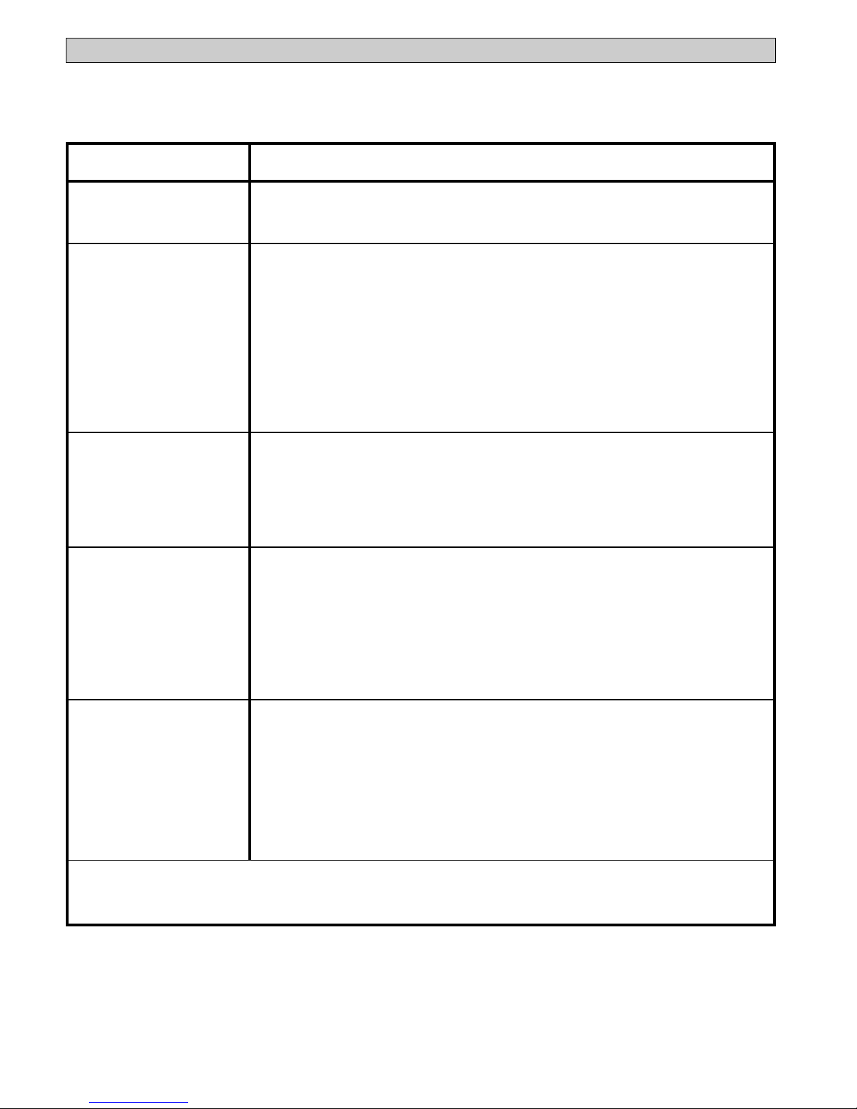
Lennox EAC-14-2 User manual

®
AIR CLEANERS/
FILTERS
HEALTHY CLIMATE®
ELECTRONIC AIR CLEANER
© 2003 Lennox Industries, Inc.
Dallas, Texas USA
INSTALLATION INSTRUCTIONS FOR LENNOX MODELS EAC-14-2, EAC-16-2 AND EAC-20-2
504,812M
06/03
Shut off power at fuse panel before
servicing. Failure to do so could result
in serious personal injury or death.
▲
!WARNING
ELECTROCUTION HAZARD
Introduction
Please read instructions before installing and using the Elec-
tronic Air Cleaner. This will help you obtain the full benefit from
the Electronic Air Cleaner you have selected. It will also help
you avoid needless service costs that result from causes we
cannot control and cannot cover in our guarantee.
1. Read this manual carefully. Failure to follow these rules
and instructions could cause a malfunction of air cleaner
or unsatisfactory service and could void your warranty.
2. Follow a regular service and maintenance schedule
to ensure efficient operation.
3. Unit must run for one full hour after installation to allow
the collecting cells to reach peak efficiency.
Do not attempt installation of this unit unless you are
familiar with the necessary tools, equipment, utility
connections and potential hazards.
Installation should be performed only by a qualified
service provider.
Failure to do so could result in reduced performance
of the unit, serious personal injury or death.
▲
!WARNING
Installation of this unit must comply with local
electric codes or other applicable codes.
Review and understand local codes prior to
installation.
▲
!WARNING
PART NO. 37-6128D
Required Tools
• Tin Snip
• Screwdriver
• Rule or Tape Measure
• Drill
Lennox Industries, Inc.
Dallas, Texas
1-800-9-LENNOX
www.lennox.com
Shipping and Packing List
Package 1 of 1 contains:
1 - EAC Cabinet
2 - Cells
1 - Power Pack
2 - Pre-Filters
1 - Wash Reminder Label
1 - High Voltage Warning Label
1 - Installation Instructions
1 - IAQ Guide and Warranty
Rules for Safe Installation and Operation
CABINET MAY CONTAIN SHARP EDGES.
Use care when servicing unit. Failure to do so could
result in personal injury.
▲
!CAUTION
EAC-14 (90N80) is designed for application with air
handlers which deliver air volumes up to 1600 cfm.
EAC-16 (X1187) is designed for application with air
handlers which deliver air volumes up to 2000 cfm.
EAC-20 (90N81) is designed for application with air
handlers which deliver air volumes up to 2200 cfm.
Electronic Air Cleaner Models
Persons with respiratory illness or conditions
should consult their physician prior to installing an
electronic air cleaner.
▲
!WARNING
Sparks which occur during air cleaner operation
may become a source of ignition.
Fire or explosion may occur if flammable vapor or
other combustible products are present while air
cleaner is operating.
Do not operate air cleaner when flammable vapor
or other combustible products are present.
▲
!WARNING

2
AB C
Unfiltered Air In Filtered Air Out
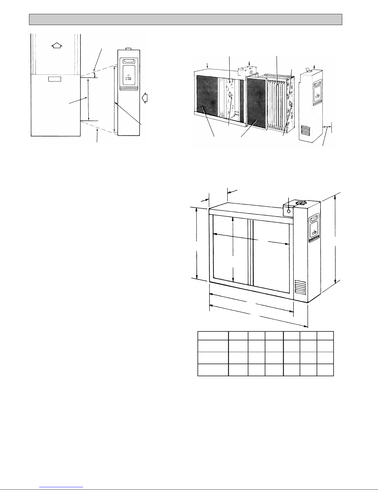
Before installing the air cleaner, make sure it is properly
sized for the application.
Model EAC-14 is designed for application with air han-
dlers which deliver air volumes up to 1600 cfm.
Model EAC-16 is designed for application with air han-
dlers which deliver air volumes up to 2000 cfm.
Model EAC-20 is designed for application with air han-
dlers which deliver air volumes up to 2200 cfm.
Refer to the specifications given on page 9.
Introduction .......................................................................... 1
Rules for Safe Installation and Operation .......................... 1
General Information ............................................................ 2
Parts Identification .............................................................. 3
Preinstallation ...................................................................... 4
Installation ........................................................................... 6
Wiring Instructions ............................................................... 7
Operation ............................................................................. 8
Maintenance ........................................................................ 8
Specifications ...................................................................... 9
Basic Service Guide .......................................................... 10
Service ............................................................................... 11
Healthy Climate®Electronic Air Cleaner Upgrade Kit ...... 13
Repair Parts ....................................................................... 14
Air is drawn into the air cleaner from the return air duct. The
air enters the pre-filters (A) where large particles (hair, lint,
etc.) are trapped. The air continues into the ionizing section
(B), where the remaining smaller particles (smoke, dust,
pollen, etc.) are given a positive electrical charge. The
charged particles enter the collecting section (C), which is a
series of aluminum plates which are alternately charged
(negative and positive). See figure 1.
The positive charge of the particles causes them to be
repelled by the positive plates and attracted to the negative
plates where they are collected . . . just as a magnet
attracts iron filings.
The filtered air continues into the air handler where it is
conditioned and distributed throughout the supply air duct
system.
White Dust (Lint)
An electronic air cleaner is designed to collect two major
types of contaminants: ➀ irritants (pollens, spores, molds,
bacteria, etc.) and ➁black soiling contaminants (dirt and
smoke particles).
The residue on the collecting plates of an electronic air
cleaner is black, indicating it is removing dirt from the air
stream. After installing an air cleaner you may notice white
dust on darker colored, flat surfaces throughout your home.
This dust typically includes long linty particles or fibers from
carpets, cotton materials or drapery fabrics. This material is
not collected by the air cleaner because it does not contain
the irritants or soiling contaminants listed above or settles
out of the air before reaching the air cleaner. The presence
of white dust does not indicate an air cleaner requires
service.
Carbon (Charcoal) Filters
Odors are gas molecules, not particles. For best odor
removal options, ask your Lennox dealer about other
Healthy Climate products, such as the PureAirTM air
purification system. However, some gases can be absorbed
by an activated carbon filter or diluted with fresh outdoor
air. When odors are present, the addition of charcoal filters
will neutralize many odors, such as cooking odors, pet
odors, cigar and cigarette odors, ozone, etc. Optional
charcoal filters are available for your Air Cleaner. Refer to
the parts list for the charcoal filter part number for your Air
Cleaner. Charcoal filters must be replaced every six
months, or more frequently if necessary. They cannot be
washed. While there is no rule of thumb for how often they
should be changed, you can use your best judgement
based on the odors you perceive in your environment.
Figure 1
Table of Contents Air Cleaner Sizing
General Information

3
Cabinet Pre-Filters Handle
Contact
Button
Contact
Button
Collecting Cells
Power Pack
Its basic components, and their functions, are as follows:
(See Figure 2)
Cabinet - mounts to existing duct and houses the collecting
cells and pre-filters.
Collecting Cells - two separate cells are included. Each
cell includes ionizing wires which charge the
particles and collecting plates which collect the
ionized dust, dirt and other impurities from the air.
Each cell must be installed with the ionizing wires
on the air entering side. Each cell must be oriented
with the handles and contact button toward the
operator. See figure 2.
Pre-filters - two sections which are interchangeable. They
trap large particles such as hair and lint before they
can enter the collecting cell sections.
Power Pack- contains solid state components that convert
the 120 volt power supply to the high-voltage,
direct current required for the collecting cells.
Figure 2
Parts Identification

4
Air Flow
Furnace
Opening
Not to Exceed 20˚
Air Flow
Electronic
Air Cleaner
Opening
Electronic
Air Cleaner
Furnace Transition Section
(if Needed)
Figure 3
Cabinet
(Interchangeable)
Collecting Cell
(Interchangeable)
Collecting Cell
Outlet Box Power Pack
Handle
Contact
Button Contact
Button
Pre-Filters
(Interchangeable) See text for Cell
Removal Clearance
Figure 4
Figure 5 - Dimensions in inches (mm)
LOCATING THE AIR CLEANER
Your air cleaner must be mounted in the return air duct of
a central forced-air system, on the air entering side of your
furnace. (See Figure 3 for example.)
Select a location that meets the following requirements:
1. Position the air cleaner so that the face of the cell is
at a right angle to the air stream.
2. Allow the following clearances to permit removal of
cells and pre-filters: (See Figures 4 and 5)
Model EAC-14 - 15 inches
Model EAC-16 - 14 inches
Model EAC-20 - 15 inches
For complete dimension data refer to Figure 5.
3. Do not install the air cleaner in the discharge air
plenum of the air handler.
4. IMPORTANT: If atomizing spray type humidifier is
used, it must be installed downstream from the air
filter.
If your furnace duct system has a pre-installed boot,
discard front cover of boot and slide the air cleaner
component inside the boot. For installation of Electronic
Air Cleaner Retrofit kit, see page 13.
If furnace opening cannot be enlarged to required size, a
sheet metal transition must be used. Transition must be
planned for each job. Reduction should not be more than
4 inches per linear foot, approximately 20 angular de-
grees (Figure 3).
DIRECTION OF AIR FLOW
THROUGH THE AIR CLEANER
Your air cleaner is shipped from the factory to allow air
flow from left-to-right. If this air flow is suitable for the
installation, no changes need to be made (Figure 4). For
right-to-left air flow, remove both pre-filter and cell sec-
tions. Turn cells upside down (with the same end
6 7/8"
(174.6)
A
B
E
D
F
C
Knockouts for
3/4" Conduit
(three sides)
facing the cabinet opening). This will locate the ionizing
wires at the right, and both contact buttons and cell
handles will be facing the power door. Air flow direction
must agree with arrow embossed on end of collecting
cells.
After installing the cell sections, install pre-filters in cabi-
net tracks on the right. This will again place the pre-filters
on the air entering side (on the same side as ionizing
wires).
Preinstallation
EAC-14 29 11/16 26 1/4 23 5/8 13 9/16 16 7/16 19 1/16
(754.1) (666.8) (600.1) (344.5) (417.5) (484.2)
EAC-16 25 1/2 21 5/16 18 5/8 17 3/4 20 5/8 23 3/8
(647.7) (541.3) (473.1) (450.9) (523.9) (593.7)
EAC-20 29 11/16 26 1/4 23 5/8 17 3/4 20 5/8 23 3/8
(754.1) (666.8) (600.1) (450.9) (523.9) (593.7)
MODEL NO. A B C D E F

5
At Least
9 Inches
Less than
7 Inches Offset
Figure 10
Air Flow
Figure 9
UPFLOW FURNACE
(Figure 9)
Installation beneath furnace.
Cleaner mounts horizontally,
where return air enters from
below. Raise furnace and in-
stall beneath base.
Air Flow
Figure 11
DOWNFLOW
FURNACE (Figure 7)
Cleaner is mounted horizon-
tally in return duct or plenum,
just above furnace.
UPFLOW FURNACE
(Figure 8)
Side installation. Cleaner
is mounted vertically,
where return air enters
side inlet of furnace.
OFFSET INSTALLATION
(Figure 10)
Typical use of duct offset to match air cleaner
opening.
If duct connection to furnace allows less than nine
inches for mounting the air cleaner, shorten the
lateral trunk, or attach an offset fitting to the elbow.
HORIZONTAL FURNACE
(Figure 11)
Cleaner is mounted vertically
in the return duct near furnace.
Air Flow
Rear View
Figure 6
Air Flow
Rear View
Figure 7
Air Flow
Figure 8
BASEMENT FURNACE
(LOWBOY) (Figure 6)
Cleaner is mounted hori-
zontally in return plenum,
just above furnace.
TYPICAL APPLICATIONS

6
Figure 12
Figure 13
Duct
Frame
Power
Supply
Box
Mounting
Holes
Air Flow Turning
Vanes
Figure 14
Optional method
(Bend tabs outward at 90˚angle)
Figure 15
REMOVE OLD FILTER AND DISCARD
(Figure 12)
NOTE - The existing filter may be installed inside the air
handler cabinet.
CLEAN BLOWER COMPARTMENT
It is suggested that the furnace blower compartment,
blower and blower housing be cleaned to ensure clean air
circulation.
INSTALLATION
The following is a typical installation of the air cleaner in
an upflow air handler application (Figure 8).
1. Place the air cleaner on the floor. Stand it upright with
the power door facing you (Figure 4). If a horizontal
installation is being planned, lay the air cleaner on its
side, this will help you to visualize the relative location
of all parts.
Allow ample space for wiring and servicing the power
supply box (Figure 13).
2. Release the latch, remove the power pack (by grasp-
ing handle and pulling power pack away from cabinet)
and set it aside. Remove the collecting cells and pre-
filters. Set pre-filters and cells aside in a safe location
until the cabinet is installed.
3. Set the cabinet next to the air handler. If necessary,
enlarge the opening in the air handler (if possible) to
match the opening in the cabinet.
If the air handler opening cannot be enlarged, a
transition fitting should be used. (Figure 3).
The cabinet can be attached directly (Figure 13), or
a starting collar can first be fitted to the air handler
inlet. A butt or slip joint can be used.
Securely attach the cabinet to air handler inlet, using
at least two of the mounting holes on each side of the
cabinet.
4. Using butt joint, attach duct (normally an elbow) to the
upstream side of air cleaner cabinet. (Note the use of
the sheet metal turning vanes inside the elbow to
improve air distribution over the face of the cells.)
(Figure 14)
NOTE: An optional method of attaching duct to the
cabinet is to modify the cabinet (Figure 15) by bending the
tabs outward at a 90° angle and attaching duct to tabs.
Transition Fittings
If the air duct does not fit the cabinet opening, a transition
should be used. Gradual transitions are preferred for
greatest efficiency. Not more than four inches per linear
foot (approximately 20° angle) should be allowed (Figure
3).
5. Connect the vertical duct section to the elbow. Wedge
a wood block between floor and elbow for support
(Figure 16).
6. Seal all joints in the return air system downstream
from the air cleaner with duct tape to prevent dust
from entering the air stream. Tape is usually applied
on the outside of ducts, but may also be applied on the
inside, or both.
Installation
Improper installation, adjustment, alteration, service
or maintenance can cause property damage, per-
sonal injury or loss of life. Installation and service
must be performed by a qualified installer or service
agency.
▲
!WARNING

7
7. With the cabinet installed, the air cleaner can now be
wired to electrical input source.
Installation of this unit must comply with local
electric codes or other applicable codes.
Review and understand local codes prior to in-
stallation.
Failure to do so could result in serious personal
injury or death.
8. Since this air cleaner unit has an air flow monitor
installed, it does not require electrical wiring through
the air handler controls. This unit requires a 120 VAC
60 Hz input circuit. A 20 amp circuit is more than
adequate.
9. Remove junction box cover and install the required
bushing into the 3/4 in. Knock out. With the supply
voltage turned off, route three (3) wires into junction
box for connections. (See Fig. 17.)
Insure all wires are clamped, wire connectors prop-
erly installed and grommets used to prevent wire
abrasion.
Vertical
Section
Wood Block
Tape All
Joints
Figure 16
Hot
Neutral
Grounding
Conductor
Front View
Figure 17
Floor
Conduit
Duct
Electronic
Air Cleaner
Figure 18
Cabinet Pre-Filters Handle
Contact
Button
Contact
Button
Collecting Cells
Power Pack
Figure 19
10. With the cabinet Installed, reinstall pre-filter(s) and
collecting cell(s) (Figure 19).
NOTE: The contact button and handles on the cell
must be facing you and ionizing wires must be on the
air intake side.
11. Install the power pack as follows:
Engage the lip on lower inside edge of power pack in
the flange on cabinet. Carefully close the power pack,
making sure that the electrical connector prongs on
the power pack enter the slots in the socket on
cabinet. When the power pack is fully in place, en-
gage the latch and snap it closed.
12. Place the small month-indicator magnet on the cur-
rent month in the table on the door. This will serve as
a reminder for the next inspection and/or cleaning.
Wiring Instructions
▲
!WARNING

8
Operating
Light
On-Off
Switch
Figure 20
1. Make sure 120VAC power is turned on at the circuit
breaker which serves the air handler. Slide the air
cleaner switch into the “ON” position (Figure 20).
2. The air cleaner should operate when the indoor
blower is on. You may hear an occasional arcing or
snapping sound. This is caused when large particles
of dirt are trapped by the air cleaner.
NOTE: If arcing is continuous, cells should be washed or
checked for other problems. Refer to Basic Service
Guide.
3. The air cleaner operating light should be ON when the
indoor blower is operating. If not, the collecting cells
may require cleaning, or there may be another prob-
lem with the air cleaner.
If, after washing the cells, the Operating Light stays off,
the cell could be wet, improperly placed in the cabinet or
may need servicing.
out of ledge at bottom edge of cabinet. Set power pack
aside.
4. Remove the cell(s) and pre-filter(s) from cabinet. Using a
solution of warm water and low sudsing detergent, soak
cell(s) and pre-filter(s) for 20 to 30 minutes. (Do not soak
charcoal filters – they must be replaced).
NOTE: Ionizing wires may become coated causing loss of
cleaning ability by the collecting cell. Using a damp cloth,
wipe each ionizing wire, exercising care not to damage
them.
5. Remove the cell(s) and pre-filter(s) from solution and rinse
thoroughly with clean water.
6 Allow cell(s) and pre-filter(s) to drip dry for a minimum of
2 hours. Cell(s) and pre-filter(s) may be tipped at a slight
angle to expedite the drip-dry process.
7. Reinstall the cell(s) and pre-filter(s) in the cabinet.
8. Replace the power pack. Turn air handler fan on. After 30
minutes push ON-OFF switch on the power pack to the
“ON” position.
A moderate amount of arcing or “snapping” may occur at
this time, which will indicate that the cell(s) are still damp.
If the noise is objectionable, push the ON-OFF switch to
the “OFF” position and allow additional time for cell(s) and
pre-filter(s) to dry. In some cases the operating light will
remain OFF during this initial activation of the air cleaner,
and this would indicate that the cell(s) are not completely
dry. After the cells are completely dry, the operating light
should remain ON while the indoor blower is on.
9. Place the small month-indicator magnet on the current
month in the table on the door. This will serve as a
reminder for the next inspection and/or cleaning.
For maximum efficiency your air cleaner cell(s) and pre-filter(s)
should be inspected once a month and cleaned when neces-
sary. Cleaning will usually be required every one to three
months, depending upon the particular household circum-
stances. When cleaning is required the following procedure
should be used:
CLEANING THE CELLS AND PRE-FILTERS
1. Turn the air handler “OFF.”
2. Push the ON-OFF switch on the power pack to the “OFF”
position (Figure 20). Wait 15 seconds for the power pack
and collecting cell(s) to automatically discharge.
3. Release the latch on top of power pack and pull the power
pack straight away from cabinet at the top. Then lift pack
Operation
Maintenance
CABINET MAY CONTAIN SHARP EDGES.
Use care when servicing unit. Failure to do so could
result in personal injury.
▲
!CAUTION
NOTE: Failure to properly maintain your air cleaner
may void your warranty.
Do not operate the blower(s) in the HVAC system
without the door on this unit securely in place. Gas
fumes which could contain carbon monoxide, can be
drawn into the living space resulting in personal
injury or death.
▲
!WARNING

9
Rated Capacity 1400 cfm 1600 cfm 2000 cfm
Max. Pressure Drop .08 in. W.G. .12 in. W.G. .09 in. W.G.
Cell Weight (2) 9 lbs. each (2) 9 lbs. each (2) 11 lbs. each
Power Pack Weight 8 lbs. 10 lbs. 10 lbs.
Unit Weight 43 lbs. 44 lbs. 52 lbs.
Power Consumption 40 Watts (Max) 40 Watts 40 Watts
Electrical Input 120 VAC 60 hz. 120 VAC 60 hz. 120 VAC 60 hz.
Electrical Output 1.2 Ma 1.5 Ma 1.7 Ma
@ 6450 VDC (nom)
Max. Ozone Generation 37 ug/min 37 ug/min 37 ug/min
Temperature Rating 40˚F to 125˚F40˚F to 125˚F40˚F to 125˚F
EAC-14 EAC-16 EAC-20
AIR CLEANER MODEL NUMBER
SPECIFICATIONS
Specifications

10
SYMPTOM POSSIBLE CAUSE
ON/OFF switch “ON” Unit functioning normally.
Blower ON
Operating Light ON
ON/OFF switch “ON” 1. Power is not being supplied to air cleaner.
Blower ON A. Check fuse or circuit breaker.
Operating Light OFF B. Ensure power pack is properly installed and latched.
2. Collecting cell shorted - Turn power Off - Remove power pack - Remove
collecting cells - Replace power pack - Restore power (ensure blower is
operating).
A. If Operating Light comes ON check cells for bent plates, loose ionizing
wire(s) or cracked insulator(s).
B. If Operating Light remains OFF, malfunction is in the power pack. (See
power supply Checkout Procedure).
ON/OFF Switch “ON” 1. Air flow sensor contaminated/misaligned
Blower OFF A. Remove power pack and clear contamination inside black bushing around
Operating Light ON the small sensor element.
B. Ensure small sensor element is centered in bushing.
2. Air sensor left in bypassed condition after servicing.**
3. Faulty air flow sensor panel.
Excessive arcing during 1. Wet collecting cell.
normal operation - A. Allow cell(s) to dry after cleaning before applying power.
Operating Light may blink 2. Damaged collecting cell(s).
A. Remove cell(s) and inspect for bent plates, loose ionizing wire(s), cracked
insulator(s), etc.
3. Collecting cells dirty.
A. Clean cells as instructed in this manual.
4. Faulty power supply (see power supply checkout procedure)
Excessive ozone odor 1. Damaged collecting cell(s).
A. Remove cell(s) and inspect for bent plates, loose ionizing wire(s), cracked
insulator(s), etc.
2. Collecting cells dirty.
A. Clean cells as instructed in this manual.
3. Faulty power supply (see power supply checkout procedure).
If excessive ozone odor continues after these items are corrected, see ozone
reduction section on page 13.
**NOTE: Your air cleaner is equipped with an air flow sensor (switch) which turns the unit ON and OFF in
response to the system blower. It may have been “wired out” during a service check and inadvertently left in this
condition
This guide covers most homeowner complaints. If, after checking the items listed, the unit still fails to operate properly,
contact your Lennox dealer.
Basic Service Guide

11
Figure 21
Do not attempt repair of this unit unless you are
familiar with the necessary tools, equipment,
utility connections and potential hazards.
Service should be performed only by a qualified
technician.
Failure to do so could result in reduced perfor-
mance of the unit, serious personal injury or
death.
This guide contains service checks to assist service
personnel in locating and correcting any malfunction that
might occur to render the air cleaner ineffective or inop-
erative. The air cleaner has been designed with replace-
able components, such as the high-voltage power supply
and air flow switch. This allows the serviceman to replace
a faulty component rather than attempt repairs of such
components in the field.
All voltage measurements indicated can be made with a
high voltage D.C. probe and a general purpose volt ohm
meter. For example: Simpson 260 or equivalent.
For test purposes, the air flow switch may be “wired out”
of the system. This will eliminate the need for air flow
across the sensing thermistor to energize the power
supply (see Fig 22).
NOTE: All tests to be performed with the Ozone Reduc-
tion Jumper intact.
NOTE: When servicing the power pack components, all
wiring must be routed to factory specifications.
The solid-state power supply is not
designed for individual component part
replacement and must be replaced as
a complete "snap-in" unit.
Input voltage: 120 VAC 60 Hz.
Output to light: 1.5 to 2.5 VDC
H.V. Output: 6450 VDC (nom)
Collecting Cell
Specifications
Power Supply
Specifications
1400 cfm - 1.2 Ma @ 6450 VDC
1600 cfm - 1.5 Ma @ 6450 VDC
2000 cfm - 1.7 Ma @ 6450 VDC
Operating
Light
Power
Supply
Cell Contact
& Insulator
ON/OFF
Switch
Cover Assembly
AirFlow Switch
Power Pack
Assembly
L1
120 VAC
Connector
Wht
Wht
Gnd
Red
Blk
Blk
Wht/Brn Wht
Blk
Blu
Wht/Brn
Wht
Blk
Blu
L2
Service
▲
!WARNING

12
1. Turn power switch to the “OFF” position and remove
the power pack from cabinet.
2. If air flow switch is installed, locate air flow switch and
remove power pack cover. If air flow switch is not
installed, go to step 4.
3. Disconnect the three-pin plastic connector and jumper
the two female pins (white wire to white-brown wire)
as shown in Fig. 22.
Jumper Lead
Female Pins
Male Pin
Plastic Connector
Method of jumping lead wires of
connector plug from air flow switch.
4. Place power pack on a well insulated workbench.
Connect meter negative (-) lead to the sheet metal
chassis and the high voltage probe to high voltage
contact on back cover of power pack. Connect AC
power to power pack using an extension cord and turn
power switch to the “ON” position. Keep hands and
tools away from high voltage contact.
5. If Operating Light comes ON and output voltage is
between 6100 and 6800 VDC, power supply is good.
6. If voltage is good but Operating Light does not come
on, replace Operating Light.
1. Connect a multimeter set to read 120 VAC to power
supply terminals marked “LINE.”
2. Connect 120 VAC to power pack plug, turn power
switch “ON.”
3. Blow on thermistor at air flow monitor. 120 VAC
should appear at multimeter. Stop blowing and volt-
age should disappear in 10 - 15 seconds.
4. If voltage did not appear (Step 3), disconnect power
to power pack. Locate air flow switch and remove
power pack cover. Disconnect the three-pin plastic
connector. Jumper the two female pins (white wire to
white-brown wire) as shown in Fig. 22. Reconnect
power to power pack. Turn power switch “ON.”
A. If 120 VAC appears at multimeter, replace air
flow monitor.
B. If 120 VAC does not appear on multimeter,
problem is other than air flow monitor. Recheck
all primary wiring.
NOTE: The air flow monitor is designed to operate in the
temperature range of 65° to 120° F. Operation outside
this range is not recommended.
POWER SUPPLY CHECK OUT PROCEDURE
1. Place collecting cell on a well insulated workbench
with the cell contact button pointing upward.
2. Select a power pack (with air flow switch bypassed
and ozone reduction jumper intact) that reads be-
tween 6100 and 6800 VDC at the cell contact with no
cell attached.
3. Place power pack on top of collecting cell ensuring
that there is proper contact between the cell contact
on the power pack contact.
4. Using a standard extension cord, apply 120 VAC to
power pack. Turn power switch to “ON” position.
5. Connect meter negative (-) lead to metal frame of
collecting cell. Use high voltage probe to measure
voltage at collecting cell ionizer or cell plates. Voltage
should be 6100 to 6800 VDC.
NOTE: A new “out-of-box” cell may cause the voltage
to be lower than normal for a short period of time. To
obtain a more accurate measurement, “age” the cell
by applying high voltage to the cell for 15 to 30
minutes.
6 If voltage is below 6100 VDC, check cell for foreign
objects, bowed/bent/loose plates, broken ionizing
wires or cracked insulators. Wash cells if required. If
Operating Light remains OFF, replace collecting cell.
CELL TEST
AIR FLOW MONITOR TEST
Support
Ionizing
Wire
If an ionizing wire should break, it can be replaced as
follows:
1. Turn off power to air handler and air cleaner and
remove collecting cells as outlined in previous sec-
tion.
2. Remove all pieces of broken wire. Make sure sup-
ports at each end are in good condition and not bent
out of shape.
3. Hook the new wire onto the support at one end.
4. Hold your finger against the support at the other end
(Figure 23) and hold the ionizing wire between thumb
and forefinger as shown or use needle nose pliers.
Press inward on spring support. Hook end of wire
over small tab at end of support and release. Make
sure wire is securely anchored at each end.
REPLACING AN IONIZING WIRE
Figure 22
Figure 23

13
OZONE WARNING
All electronic air cleaners produce a small amount of
ozone. Some individuals are sensitive to ozone and
may notice an odor or may experience a physiological
response (including lung irritation), especially at high
altitudes or low airflow rates. In such cases, there are
two options available to reduce ozone concentrations:
Option 1 — Cut Jumper: A hairpin-shaped jumper wire
labeled W1, which is located in the power supply (see
Figure 24), can be cut and separated. This will reduce
the maximum operating power and reduce the ozone
generated by as much as 15 percent. It will reduce the
air cleaning efficiency by 5 to 10 percent.
Option 2 — Charcoal Filter: Charcoal filters (available
as an accessory item, see page 15) reduce the ozone
output of the electronic air cleaner without sacrificing
cleaning efficiency. In independent laboratory testing, a
LINE
WHT/BRN BLK
W1
E3 E2
Cut and separate
Ozone Reduction
Jumper
Cabinet Pre-Filters Handle
Contact
Button
Contact
Button
Collecting Cells
1. Remove existing door from the media air cleaner
cabinet.
2. Remove existing media cartridge from air cleaner
cabinet.
3. Remove the two pre-filters from the electronic air
cleaner upgrade kit and insert into cabinet tracks
opposite the air handler (see Fig. 25). These will be
used to catch the larger particles that are in the air
stream before entering the collecting cells.
4. Insert the two collecting cells into the cabinet behind
the pre-filters. Be sure ionizing wires are directly
behind the pre-filters so the particles can be charged
as soon as the air leaves the pre-filters.
5. Remove cover plate on the power supply junction box
and remove the knockout needed to bring the wire to
the female receptacle.
6. Position receptacle with ground in the down position
as shown in Fig. 17 and pull wires through the
receptacle locator on the junction box. Snap the
receptacle into the hole until secure. Connect ground
wire from receptacle and ground wire in kit to cabinet
using rivet and washer as follows:
a) Place washer on rivet
b) Place terminal from ground wire on rivet
c) Place terminal from receptacle ground wire on
rivet
d) Place rivet in hole in junction box and secure to
cabinet.
Healthy Climate®Electronic Air Cleaner Upgrade Kit
OZONE REDUCTION
Figure 25
7. For wiring installation (see page 7 and follow all wiring
instructions 7, 8 and 9).
8. Install the power pack (see page 7 instruction 11).
9. For operation (see page 8 – Operation).
Improper installation, adjustment, alteration, service
or maintenance can cause property damage, per-
sonal injury or loss of life. Installation and service
must be performed by a qualified installer or service
agency.
▲
!WARNING
INSTALLATION
Do not operate the blower(s) in the HVAC system
without the door on this unit securely in place. Gas
fumes which could contain carbon monoxide, can be
drawn into the living space resulting in personal
injury or death.
▲
!WARNING
new charcoal filter was shown to eliminate nearly all of
the ozone generated by the electronic air cleaner. Over
time, however, the charcoal filter becomes less
effective at eliminating ozone. Charcoal filters should be
replaced approximated every six months. Highly
sensitive individuals may elect to replace their charcoal
filters more frequently.
Refer to the Basic Service Guide on page 10 for
additional items which may reduce ozone.
Ozone
Reduction Jumper
Figure 24

14
12
2
334
5
6
8
Replacement Parts

15
PARTS LIST FOR ELECTRONIC AIR CLEANERS
When ordering replacement parts, always give the following informa-
tion as shown in this list.
1. The PART NUMBER
2. The PART DESCRIPTION
3. The MODEL NUMBER
4. The NAME OF ITEM - Electronic Air Cleaner.
Always order by “PART NUMBER” . . . Not by “ITEM NUMBER”
ITEM
NO. DESCRIPTION PART NUMBER
EAC-14 EAC-16 EAC-20
Electronic Air Cleaner 90N80 X1187 90N81
1 Cabinet 69H84 X1188 72H01
2 Pre-Filter •69H85 •X1189 •72H02
3 Collecting Cell •69H86 •X1190 •72H03
4 Power Pack Assembly 80K62 X1191 80K63
5 Ionizing Wire 69H91 X1192 72H05
6 Power Supply 80K64 80K64 80K64
7†Charcoal Filter (w/clips) (First Inst.) •69H98 •X1194 •72H09
8 Air Flow Switch (w/Mtg.Hdwr) 80K61 80K61 80K61
•Two (2) Required
†Not Shown
Contact your local Lennox dealer to order replacement parts. For the Lennox dealer
nearest you, dial 1-800-9-LENNOX, or visit www.lennox.com.


®
ÉPURATEURS ET
FILTRES À AIR
ÉPURATEUR D’AIR ÉLECTRONIQUE
HEALTHY CLIMATE®
© 2003 Lennox Industries, Inc.
Dallas, Texas USA
INSTRUCTIONS D’INSTALLATION, MODÈLES LENNOX EAC-14-2, EAC-16-2 ET EAC-20-2
504,812M
06/03
Avant de réviser l’appareil, couper le courant
au panneau de distribution. Si ces instruc-
tions n’étaient pas respectées, des blessures
graves, voire un décès, pourraient survenir.
▲
!MISE EN GARDE
RISQUE D’ÉLECTROCUTION
Introduction
Veuillez lire les directives avant d’installer et d’utiliser l’épurateur
électronique, ce qui vous permettra de profiter pleinement des avan-
tagesdecetappareil.Vouséviterezaussidesdépensesderéparation
supplémentaires qui découlent de facteurs qui sont indépendants de
notre volonté et que notre garantie ne peut protéger.
1. Lireattentivementleprésentguide.Sisesdirectivesn’étaientpas
suivies,l’appareilrisqueraitdefonctionnerincorrectementoupas
du tout et votre garantie pourrait être annulée.
2. Effectuer régulièrement les révisions et l’entretien afin d’assurer
un fonctionnement efficace de l’appareil.
3. L’appareil doit fonctionner pendant une heure complète
immédiatement après son installation afin d’assurer l’efficacité
optimale des cellules collectrices.
Ne pas tenter d’installer l’appareil avant de s’être familiarisé
complètement avec les exigences en matière d’outils, d’équi-
pementsetderaccordementsauxservicespublicsainsiqu’avec
les dangers qui sont présents.
Pour installer l’appareil, il est recommandé de faire appel à un
fournisseur de services agréé.
Si ces instructions n’étaient pas suivies, les performances de
l’appareil pourraient être réduites et des blessures graves,
voire un décès, pourraient survenir.
PIÈCE No37-6128D
Liste d’emballage et d’expédition
Le colis 1 de 1 contient :
1 - Boîtier de l’épurateur d’air électronique
2 - Cellules
1 - Module d’alimentation
2 - Préfiltres
1 - Étiquette de rappel de lavage
1 - Étiquette de mise en garde pour haute tension
1 - Mode d’emploi
1 - Guide QAI et garantie
Installation et exploitation sécuritaires
EAC-14 (90N80) : conçu pour usage avec les générateurs ayant un
débit d’air maximum de 1600 pi3/min.
EAC-16 (X1187) : conçu pour usage avec les générateurs ayant un
débit d’air maximum de 2000 pi3/min.
EAC-20 (90N81) : conçu pour usage avec les générateurs ayant un
débit d’air maximum de 2200 pi3/min.
Modèles d’épurateur d’air électronique
▲
!MISE EN GARDE
L’installationde l’appareil doitrespecter lescodes del’électri-
cité et tout autre code en vigueur.
Avant de procéder à l’installation, prendre soin de vérifier les
codes en vigueur.
Outils requis
• Cisailles de ferblantier
• Tournevis
• Règle ou ruban à mesurer
• Perceuse Lennox Industries, Inc.
Dallas, Texas
1-800-9-LENNOX
www.lennox.com
LE BOÎTIER PEUT AVOIR DES BORDS COUPANTS.
Manipuler soigneusement l’appareil lors de la révision. Si ces
instructionsn’étaient pas suivies, des blessures légères pour-
raient survenir.
▲
!ATTENTION
▲
!MISE EN GARDE
Les personnes souffrant de maladies respiratoires doivent
consulter leur médecin avant d’installer un épurateur d’air
électronique.
▲
!MISE EN GARDE
Les étincelles dégagées durant le fonctionnement normal de
l’épurateur peuvent constituer des sources d’inflammation.
Unfeuouuneexplosionpeutsurvenirsiunevapeurinflamma-
ble ou tout autre produit combustible est présent lorsque
l’épurateur est en marche.
Ne pas faire fonctionner l’épurateur en présence d’une vapeur
inflammable ou de tout autre produit combustible.
▲
!MISE EN GARDE

2
ABC
Entrée d’air non filtré Sortie d’air filtré
Avant d’installer l’épurateur, s’assurer qu’il est de capacité suffisante.
Modèle EAC-14 : conçu pour usage avec les générateurs ayant un
débit d’air maximum de 1600 pi3/min.
Modèle EAC-16 : conçu pour usage avec les générateurs ayant un
débit d’air maximum de 2000 pi3/min.
Modèle EAC-20 : conçu pour usage avec les générateurs ayant un
débit d’air maximum de 2200 pi3/min.
Se reporter à la fiche technique de la page 9.
Introduction .............................................................................. 1
Installation et exploitation sécuritaires.................................... 1
Généralités .............................................................................. 2
Identification des pièces.......................................................... 3
Installation préliminaire ........................................................... 4
Installation ............................................................................... 6
Câblage ................................................................................... 7
Exploitation .............................................................................. 8
Entretien .................................................................................. 8
Fiche technique ....................................................................... 9
Guide de révision de base .................................................... 10
Révision ................................................................................. 11
Ensemble d’épurateur d’air électronique
Healthy Climate®pour mise à niveau ............................ 13
Pièces de rechange............................................................... 14
L’air est aspiré vers l’épurateur par les conduits de reprise d’air. Il
traverse d’abord le préfiltre (A), qui capte les grosses particules
(phanères,mousse,etc.).Ilpasseensuitedansl’étaged’ionisation(B),
où les petites particules toujours présentes (fumée, poussière, pollen,
etc.) reçoivent une charge électrique positive. Ces particules ionisées
pénètrent alors dans l’étage collecteur (C), formé d’une série de
plaques d’aluminium dotées en alternance d’une charge négative ou
positive (figure 1).
Les particules étant dotées d’une charge positive, elles sont repous-
séesparles plaquespositives etattirées parlesplaquesnégatives, où
elles s’accumulent, comme la limaille de fer sur un aimant.
L’air filtré passe enfin dans le générateur d’air, où il est conditionné et
distribué vers le réseau de conduits.
La poussière blanche (les peluches)
L’épurateur est conçu pour capter principalement deux sortes de
contaminants : (1) Les irritants (pollen, spores, moisissure, bactéries,
etc.); et (2) les contaminants salissants (particules de saleté et de
fumée).
Les résidus qui s’accumulent sur les plaques d’un épurateur électroni-
que sont noirs; toute cette saleté est retirée de l’air ambiant. Après
l’installationdel’épurateur,onpeutapercevoir,partoutdanslamaison,
de la poussière blanche sur les surfaces de couleur foncée. Elle est
généralement formée de longues particules de peluches ou de fibres,
provenant de moquettes, de coton et de rideaux. Ces substances ne
sontpascaptéesparl’épurateur,soitparcequ’ellesnecontiennentpas
les irritants et les contaminants mentionnés plus haut, soit parce
qu’elles se sont déposées avant d’avoir pu atteindre le filtre. La
présence de poussière blanche ne signifie pas qu’il est temps de faire
réviser l’épurateur.
Figure 1
Table des matières Capacité des épurateurs
Généralités
Les filtres à charbon actif
Les odeurs sont causées par des molécules de gaz et non par des
particules. Pour connaître le meilleur moyen d’éliminer les odeurs,
consulter le détaillant Lennox à propos des autres produits Healthy
Climate, comme l’équipement de purification de l’air PureAirMC. Or, il
est possible d’adsorber certains gaz à l’aide d’un filtre à charbon actif
ou de les diluer par un apport d’air frais en provenance de l’extérieur.
Si des odeurs sont présentes, comme les odeurs de cuisson, d’ani-
maux de compagnie, de cigare ou de cigarette, etc., l’ajout d’un filtre à
charbon actif peut les neutraliser. On peut se procurer des filtres à
charbonfacultatifspourusageavecl’épurateurd’airélectronique.Pour
en connaître le numéro de pièce, se reporter à la liste de pièces
correspondant à l’épurateur installé. Les filtres à charbon ne peuvent
être lavés; on doit les remplacer tous les six mois, plus souvent si
nécessaire. Il n’existe aucune règle générale quant à la fréquence de
leur changement; nous vous recommandons simplement de faire
appel à votre jugement en fonction des odeurs perçues dans le foyer.

3
Boîtier Préfiltres
Poignée
Boutonde
contactBoutonde
contact
Cellulescollectrices
Module
d’alimentation
Voiciunebrèvedescription desprincipauxcomposantsde l’appareilet
de leurs fonctions (voir la figure 2).
Leboîtier : Installédans lesconduitsexistants, ilrenfermeles cellules
et les préfiltres.
Les cellules collectrices : Deux cellules sont incluses. Chacune
comporte des fils ionisants, qui donnent une charge électri-
queauxparticules,etdesplaquescollectrices,quicaptentla
poussière, la saleté et toute autre impureté de l’air qui a été
ionisée.
Chaque cellule doit être installée avec les fils ionisants
orientés vers l’entrée d’air. Chaque cellule doit être orientée
pourquelespoignéesetleboutondecontactsoientorientés
vers l’utilisateur (figure 2).
Les préfiltres : Composés de deux sections interchangeables, ils
servent à capter les grosses particules, comme les cheveux
etlespoils,pour lesempêcher depénétrerdans lescellules.
Le module d’alimentation : Doté de composants à circuits intégrés,
il convertit le courant d’alimentation de 120 volts C.A. en
courantcontinuàhautetensionquiestrequisparlescellules
collectrices.
Figure 2
Identification des pièces

4
EAC-14 29 11/16 26 1/4 23 5/8 13 9/16 16 7/16 19 1/16
(754,1) (666,8) (600,1) (344,5) (417,5) (484,2)
EAC-16 25 1/2 21 5/16 18 5/8 17 3/4 20 5/8 23 3/8
(647,7) (541,3) (473,1) (450,9) (523,9) (593,7)
EAC-20 29 11/16 26 1/4 23 5/8 17 3/4 20 5/8 23 3/8
(754,1) (666,8) (600,1) (450,9) (523,9) (593,7)
MODÈLE N
o
A B C D E F
Écoulement
de l’air
Ouverture du
générateur
Ne pasdépasser 20°
Écoulement
de l’air
Ouverture de
l’épurateur
électronique
Épurateur d’air
électronique
GénérateurSection de transition
(au besoin)
Figure 3
Boîtier
Cellulecollectrice
(interchangeable)Cellulecollectrice
(interchangeable)
Boîte de
raccordementModule
d’alimentation
Poignée
Bouton de
contactBouton de
contact
Préfiltres
(interchangeables) Voir letexte concernant
ledégagementrequis
pourenlever lescellules
Figure 4
Figure 5 - Dimensions en pouces (mm)
CHOIX DE L’EMPLACEMENT DE
L’ÉPURATEUR
Installer l’épurateur dans le conduit de reprise d’air d’un système
central à air pulsé, en amont du générateur. (Voir l’exemple à la
figure 3.)
Choisir un emplacement conforme aux critères suivants :
1. Positionner l’épurateur pour que la face de la cellule se trouve
perpendiculaire à l’écoulement de l’air.
2. Assurerlesdégagementssuivantsafindepermettreledémontage
des cellules et des préfiltres (voir les figures 4 et 5) :
Modèle EAC-14 : 38 cm (15 po)
Modèle EAC-16 : 36 cm (14 po)
Modèle EAC-20 : 38 cm (15 po)
Les dimensions exactes sont données à la figure 5.
3. Ne pas installer l’épurateur dans le plénum de sortie d’air du
générateur.
4. IMPORTANT : Si un humidificateur à pulvérisation est utilisé, il
doit être installé en aval de l’épurateur.
Si le réseau de conduits du générateur comporte déjà un boîtier
intégré,en jeter lecouvercle etglisser l’épurateuren placeà l’intérieur
Pour l’installation d’un ensemble de mise à niveau de l’épurateur, se
reporter à la page 13.
S’il est impossible d’agrandir suffisamment l’ouverture du générateur,
il faut installer une transition en tôle. La transition doit être adaptée à
chaqueinstallation.Lefacteurderéductionnedoitpasdépasser28 cm
au mètre (ou 4 pouces au pied linéaire), soit une pente d’environ
20 degrés (figure 3).
SENS DE PASSAGE DE L’AIR
DANS L’ÉPURATEUR
Sur livraison, l’épurateur est agencé pour que l’air circule de gauche à
droite. Si cela convient à l’installation, aucune modification n’est
requise (figure 4). Pour permettre que l’air circule de droite à gauche,
retirer les préfiltres et les cellules. Les retourner en gardant la même
extrémité orientée vers l’ouverture du boîtier. Cela placera les fils
ionisants à droite ; de plus, les deux boutons de contact ainsi que les
poignées seront orientés vers le capot du module d’alimentation. L’air
doit traverser le filtre dans le sens indiqué par les flèches qui sont
estampées sur l’extrémité des cellules.
Une fois les cellules installées, installer les préfiltres dans les rainures
surle côtédroit duboîtier. Les préfiltresse trouverontalors ducôté de
l’appareil où l’air entre (soit du même côté que les fils ionisants).
6 7/8 po
(174,6)
A
B
E
D
F
C
Ouvertures pour
conduit de
19mm (3/4 po)
(sur trois côtés)
Installation préliminaire
This manual suits for next models
2
Table of contents
Languages:
Other Lennox Air Cleaner manuals

Lennox
Lennox HEPA Bypass Air Filtration Systems HEPA-20 User manual

Lennox
Lennox BMAC-12C User manual

Lennox
Lennox Healthy Climate PureAir PCO-20P-2 User manual

Lennox
Lennox PureAir PCO3S-14-16 User manual

Lennox
Lennox PureAir PCO-12C-2 User manual

Lennox
Lennox Healthy Climate PMAC-12C User manual

Lennox
Lennox Healthy Climate PMAC-20C User manual

Lennox
Lennox PUREAIR PCO14-23 User manual

Lennox
Lennox Variable Speed Air Handler CBX40UHV User manual

Lennox
Lennox 91W54 User manual