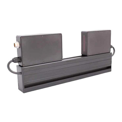
Pipe Inner Diameter Measurement Machine, RF096-32/42-80 Series
5
RF096-32/42-80 [Revision 1.1.0] 03.11.2017
where:
1 - measurement module,
2 - controller with the power supply,
3 - foot switch,
4 - personal computer with a service program.
The measurement module structural design is illustrated in Figure 2.
Figure 2.
The measurement module includes a base, on which the rotation mechanism and
the linear movement mechanism are installed. The housing of the measurement module is
equipped with a signal tower (not shown).
The rotation mechanism includes a stepper motor (1), encoder (2), shaft (3) with a
V-block (4). The transmission of rotation from the stepper motor (1) to the shaft (3) is
carried out by means of a belt drive (5). The V-block (4) is intended to install the controlled
pipe (6) and has two plate springs (7), which intended for holding the pipe on the V-block,
and a calibration ring (8). The pipe must be pressed to the thrust plate (14).
The linear movement mechanism includes guide rails (9), carriage (10), stepper
motor (11), end switch (12). The carriage (10) is moved by a ball screw, and carries a laser
triangulation sensor (13).
The machine operates as follows:
The operator installs the controlled pipe (6) into the V-block (4). On the operator's
command, a laser sensor (13) moves into the control zone of the calibration ring (8), and the
V-block (4) is driven to rotate. During rotation, a laser sensor measures the distance to the
surface of the ring in synchronization with the angle of rotation determined by the encoder
(2). Upon completion of one turn of the V-block, a laser sensor moves to the next control
position, and the measurement process is repeated. The number of diameter control
sections along the pipe is defined by the software.
Radial coordinates of the calibration ring surface and controlled pipe are
transmitted to the PC for calculating the required geometric parameters.
8. Connection
Make connections in accordance to block diagram shown in Figure 1. Connect
measurement module to controller by means of two cables (Ethernet and Power supply).
Connect foot switch to controller. Connect controller to PC and to 220 V AC.
9. Network setting
The machine is shipped with the following default network configuration: IP address
of the machine – 192.168.1.3.
Configure your PC's network card in the following address space: 192.168.1.Х.
Connect the machine directly to your PC or through the network switch.
