VERDEGRO TMA-US 100K Installation guide

Operation and Maintenance
VERDEGRO TMA-US (100K)
READ BEFORE USE!
ONLY AUTHORIZED PERSONS MAY WORK WITH THE MACHINE
IMPROPER USE CAN CAUSE SERIOUS INJURIES!
All maintenance and repair should be done by the manufacturer or under
their supervision by an official distributor. Each TMA should be delivered
with 3 certificates to guarantee the right performance.

Page 2of 38
Manual TMA-US-100K
Index
1Data producer and specific machine: ............................................................................................. 4
2Introduction:................................................................................................................................... 5
3Recognition and dimensions .......................................................................................................... 6
3.1 Photos of a typical TMA-US 100K............................................................................................ 6
3.2 Cushion dimensions and details.............................................................................................. 7
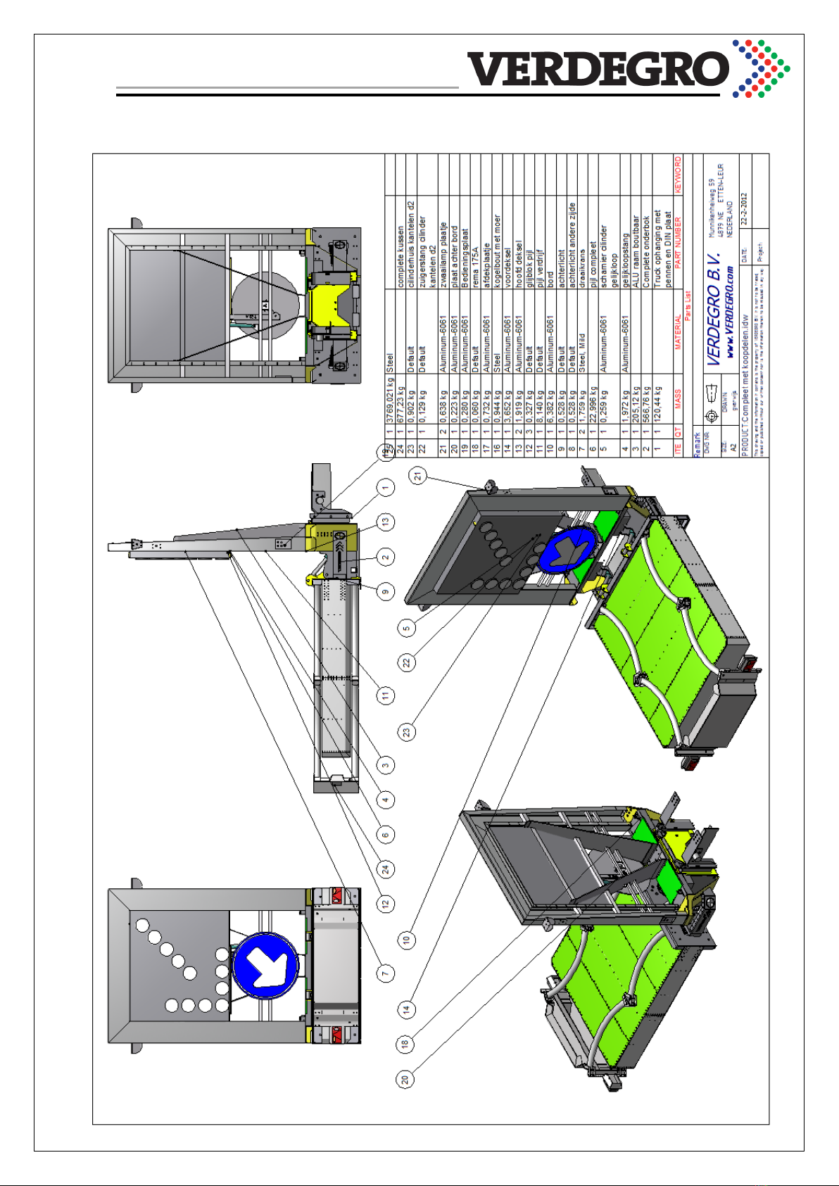
3.3 Drawing TMA with optional frame for rotatable arrow:......................................................... 8
3.4 Drawing TMA with optional frame for LED display or arrow panel: ....................................... 9
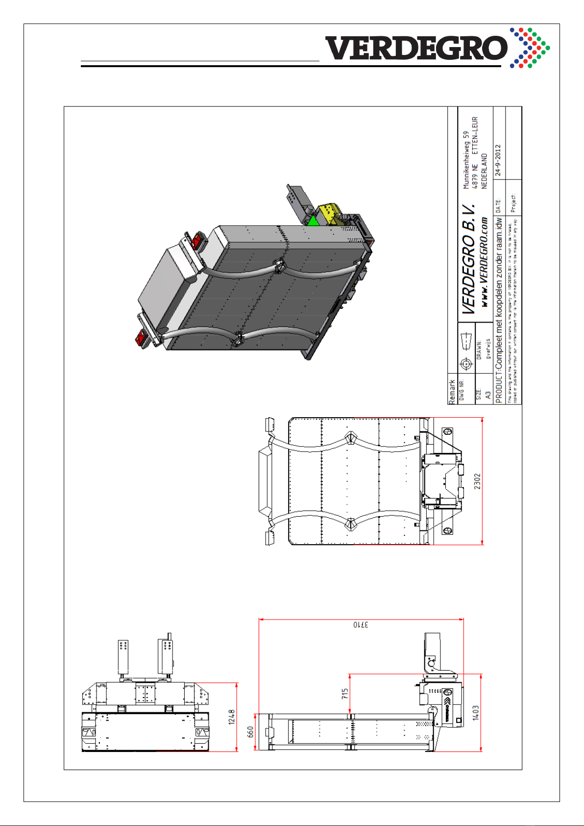
3.5 Transport dimensions............................................................................................................ 10
3.6 Operational dimensions ........................................................................................................ 11
3.7 Rotating mechanism.............................................................................................................. 12
4Technical data............................................................................................................................... 13
4.1 Table ...................................................................................................................................... 13
4.2 Hydraulic schedule with optional cylinder for rotatable arrow............................................ 14
5General specifications and instructions ....................................................................................... 15
5.1.1 Description of system.................................................................................................... 15
5.1.2 Performance criteria ..................................................................................................... 17
6Safety ............................................................................................................................................ 18
7Operation...................................................................................................................................... 20
8Supporting vehicle and adjustment.............................................................................................. 21
8.1 Specifications for mounting .................................................................................................. 22
8.1.1 DIN mounting system.................................................................................................... 22
8.1.2 Six pin mounting system................................................................................................ 23
9Inspection ..................................................................................................................................... 25
9.1 Inspection table..................................................................................................................... 25
9.2 Control position Crash Cushion............................................................................................. 26
9.3 Use of the machine in cold.................................................................................................... 26
9.4 High voltage........................................................................................................................... 26
10 Maintenance................................................................................................................................. 27
10.1 Check hydraulic oil................................................................................................................. 27
10.2 Torque index Tension............................................................................................................ 28
11 General control points of TMA..................................................................................................... 29
12 Repairs (by manufacturer or official distributor) ......................................................................... 30
12.1 Welding ................................................................................................................................. 30

Page 3of 38
Manual TMA-US-100K
12.2 Other welding........................................................................................................................ 30
13 Warranty....................................................................................................................................... 31
14 Document delivered by each TMA ............................................................................................... 32
14.1 Crash cushion certificate, signed by the Verdegro Group..................................................... 32
14.2 TMA certificate, signed by the Verdegro Group ................................................................... 33
14.3 Overall and mounting certificate .......................................................................................... 34
14.4 Sticker on chassis of TMA...................................................................................................... 35
14.5 Sticker on the cushion of the TMA........................................................................................ 36
15 CE certification.............................................................................................................................. 37
16 Maintenance history..................................................................................................................... 38

Page 4of 38
Manual TMA-US-100K
1Data producer and specific machine:
Verdegro Group
Munnikenheiweg 59
4879 NE Etten-Leur
The Netherlands
(T) +31(0)76-5017990
(F) +31(0)76-5019404
(W) www.verdegro.com
Date release : _____________________
Machine number : _____________________
Cushion number : _____________________
Company stamp:
Note: This document is only valid with an original company stamp of the producer.

Page 5of 38
Manual TMA-US-100K
2Introduction:
A Truck Mounted Attenuator (TMA) is an energy absorbing device attached to the rear of a truck or
utility vehicle. A TMA is designed to provide a controlled stop of a vehicle impacting the rear of the
truck. TMAs have been used since the mid- 1970's to reduce the severity of impacts between errant
motorists and slow moving or stopped shadow vehicles used to protect highway maintenance
workers.
The National Cooperative Highway Research Program Report 350 (NCHRP 350) specifically addresses
the performance requirements of TMAs. The recommended tests to evaluate TMA crash
performance are defined for two different Test Levels. The basic Test Level, TL-2, is conducted at a
nominal impact speed of 70 kph. TL-3 is the higher test level and is conducted at 100 kph.
This report presents the manual for the Verdegro TMA, type US at the more demanding NCHRP 350
TL-3 test conditions.
The Verdegro TMA-US 100K, in this manual called TMA is a device with an optional framework for a
sign, eventually with LED arrow or LED display. The TMA is fully hydraulic operated and must be
placed behind a supporting truck with a minimum weight of 8.000 Kg and a maximum weight of
12.000kg12 for best performance results. The crash cushion mounted on this TMA is 100K, which
means test with the TMA were done according TL-3 of the Report NCHRP-350.
The TMA is amply equipped with features that promote safety. By inspect them, the quality,
efficiency and safety of the TMA improved.
Check the condition of the TMA daily before starting work on the base of the instructions. It is strictly
forbidden to use the TMA when it is damaged, not maintained or inspected.
The Manufacturer reserves the right to the machine construction, parts and maintenance
instructions without notice.
This manual is only for the Verdegro TMA-US-100K. Some drawings or colors in this manual
can be slightly different from the delivered model which should be recognized as a typical
Verdegro TMA-US 100K.
Attention! Before maintenance or checks, disconnected the power!
1For some countries other specifications are mandatory. See chapter “supporting vehicle” for specifications.
2If you have a truck which is heavier, contact Verdegro or your distributor.

Page 6of 38
Manual TMA-US-100K
3Recognition and dimensions
3.1 Photos of a typical TMA-US 100K

Page 7of 38
Manual TMA-US-100K
3.2 Cushion dimensions and details

Page 8of 38
Manual TMA-US-100K
3.3 Drawing TMA with optional frame for rotatable arrow:

Page 9of 38
Manual TMA-US-100K
3.4 Drawing TMA with optional frame for LED display or arrow panel:

Page 10 of 38
Manual TMA-US-100K
3.5 Transport dimensions

Page 11 of 38
Manual TMA-US-100K
3.6 Operational dimensions

Page 12 of 38
Manual TMA-US-100K
3.7 Rotating mechanism

Page 13 of 38
Manual TMA-US-100K
4Technical data
4.1 Table
Description
Dimension
Min. height Cushion from the ground
200 mm
Max. height Cushion from the ground
280 mm
Max. height behind truck
4,0 m
Transport width
2,3 m
Transport height
3,7 m
Total weight
Approx.950 kgs
Hydraulic pressure
100 bar
Hydraulic gear pump (thermal secure !)
12cc
Contents of hydraulic tank
10 L
Power hydraulic pump
2,2 Kw
Equipped with thermo switch
Yes
Hydraulic rotating cylinders
2
Standard Hydraulic pump motor voltage
24 V
Standard driving lights
24 V
Battery Bank
Optional
Safety fuse
200A
Cable from truck to TMA
25 mm²

Page 14 of 38
Manual TMA-US-100K
4.2 Hydraulic schedule with optional cylinder for rotatable arrow

Page 15 of 38
Manual TMA-US-100K
5General specifications and instructions
A. Always make sure the system is delivered with the right certificates, stickers and
documentation!. Do not remove the sticker(s)!!
B. Make sure the validation time of the certificates is never exceeded!
C. Never remove safety instructions of the TMA!
D. All Verdegro Truck Mounted Attenuators (Verdegro TMA) shall be designed and
manufactured by the Verdegro Group, in accordance with the specifications.
E. The Verdegro TMA is an attenuator system designed for installation at the back of trucks
with gross vehicle weight (GVW) ranges between 8000 kg and 12 000 kg3(Contact your
country for other specifications!).
Note: Any added ballast must be adequately anchored to the truck so that it will not move
during impacts. Because the back end of the truck supports the weight of the rearward
protruding TMA, care must be taken not to exceed the manufacturer's published maximum
axle loads. To ensure that the driving characteristics of the vehicle are maintained, the
manufacturer's recommended center-of-gravity zone should also be adhered to.
F. A truck equipped with a Verdegro TMA shall have a forward skid distance of less than 10 m
during an impact by either an 820 kg or 2000 kg vehicle traveling at a design speed of 100
kph. The minimum forward skid distance is dependent on the truck’s transmission being in
second gear, and the parking brake set with the truck situated on clean, dry pavement.
5.1.1 Description of system
A. The Verdegro TMA shall consist of the following basic components: An aluminum foldex box
with 4 aluminum Cartridges, a steel Support Structure and a Support Frame with 2 mounting
options for attaching the system to the truck.
A hydraulic system shall also be included in the system to raise the structure and cartridges
to a vertical position. When the system is in a horizontal position, the frame assembly shall
be capable of collapsing when impacted by an errant vehicle. No portion of the system shall
protrude forward under the truck during an impact. The total mass of the system shall be
approximately 980 kg. The complete Verdegro TMA is designed to make attachment or
detachment from the truck simple and fast.
B. The Verdegro TMA shall have a standard trailer lighting system. This system shall include
brake lights, taillights and turn signals. The wiring for the rear lights shall be routed and
secured on the articulating frame. This system also has additional lights on the cartridge so
that the lighting system meets the standards, whether the system is in its horizontal or
vertical orientation.
C. Under the support frame are two tubes to lift the complete system with a forklift, for
example to mount on the truck.
3If you have a truck which is heavier, contact Verdegro or your distributor.

Page 16 of 38
Manual TMA-US-100K
D. The rear impact surface of the articulated frame assembly, when in the horizontal position,
shall display a red / white or yellow / black striping (Preferred reflective).
E. All welding is done by, or under the direction of, a certified welder. Metal work shall be made
at the Verdegro Group.
F. All exposed steel surfaces on the TMA shall be primed and painted and or galvanized.
G. The TMA shall be assembled with Commercial Quality bolts, nuts, and washers conforming to
European Standards.
H. The hydraulic system shall consist of a pump with a 12 or 24 (standard) volt DC motor,
cylinders, hoses, switches, wiring, and necessary subcomponents to tilt the frame assembly
to a 90° position from horizontal. The complete hydraulic system, including the pump and
hoses, shall be factory assembled and mounted to the TMA by the Verdegro Group.
I. The complete hydraulic system shall be factory assembled and mounted to the TMA. Once
assembled, each system shall be operated through ten (10) complete cycles (horizontal,
tilted to 90 position and lowered back to horizontal is one cycle) to ensure proper operation
of the pump and tilting mechanism. The hydraulic system shall be shipped assembled.

Page 17 of 38
Manual TMA-US-100K
5.1.2 Performance criteria
A. The Verdegro TMA, when mounted to a truck weighing up to 9,000 kg situated on clean dry
pavement with the transmission in second gear and the brakes locked shall perform as
follows:
1) Vehicles with a mass of 820 kg impacting straight into the rear of the TMA at 100 kph
shall remain upright with the theoretical occupant impact velocity of 12 m/s or less and
the occupant ride down acceleration of 20 g's or less per NCHRP 350, Test 3-50
evaluation criteria. The truck shall be placed against a non-moving wall, also called a rigid
barrier, during this test.
2) Vehicles with a mass of 2000 kg impacting straight into the rear of the TMA at 100 kph
shall remain upright with the theoretical occupant impact velocity of 12 m/s or less, and
the occupant ride down acceleration of 20 g's or less per NCHRP 350, Test 3-51
evaluation criteria.
3) Vehicles with a mass of 2000 kg impacting straight into the rear of the TMA at 100 kph,
and an offset of W/3 with respect to the TMA centerline, shall remain upright with no
significant roll pitch or yaw per NCHRP 350 optional Test 3-52 evaluation criteria.
4) Vehicles with a mass of 2000 kg impacting at 10 degrees into the rear of the TMA at 100
kph (62 mph) and an offset of W/4 at an angle of 10 degrees with respect to the TMA
centerline, shall remain upright with the theoretical occupant impact velocity of 12 m/s
or less and the occupant ride down acceleration of 20 g's or less per NCHRP 350, optional
Test 3-53 evaluation criteria.
5) To minimize potential damage to the truck, no portion of the TMA’s structure or energy
absorbing elements shall protrude forward of the underride during an impact. Certified
test results and associated test reports and films produced in the guideline with NCHRP
350 procedures shall be submitted showing that the TMA system conforms with all test
and performance criteria in this specification.
B. The Verdegro TMA cartridges shall successfully perform to accelerated vibration, moisture
and corrosion.

Page 18 of 38
Manual TMA-US-100K
6Safety
1. Read these instructions carefully before using the “TMA”
2. The TMA should not be used without knowledge of the operating instructions and safety
precautions. Keep the operating instructions, always within easy reach of the machine, the
operator's manual should ALWAYS be at or near the machine.
3. The operator of the TMA must be at least 18 years old and experienced in serving Truck
Mounted Attenuators.
4. The owner/holder of the TMA must ensure that all users are trained in the use of the
machine.
5. Be careful when the machine is used near live power lines.
6. Transport the TMA only if it is properly secured to vehicle.
7. On the platform are no persons during storage and adjustment of the machine or in transit.
8. Make use at all times during the adverse influences of wind, rain, temperature, brine,
thunderstorms, snow, hail and ice.
9. Use the TMA purely as Truck Mounted Attenuator, and not as a lifting mechanism or other
device.
10. The wind load of the TMA does not increase with additional signs or other objects that could
catch wind.
11. Set the whole machine back together in a smooth continuous motion so as to avoid shock
effects of road users.
12. Inspect the entire machine for loose materials such as bird nests, twigs, leaves, but also
tools, bolts, nuts, etc. which may end up on the lanes during mobilization or transport.
13. Do not hoist the TMA!
14. The safety devices are not deactivated. Defective safety devices or by a qualified repair
service company to recover before the TMA is used again.
15. Before and during operation of the machine always look at / near the machine, no persons
are present, guiding also takes into account the rotation range of the machine!
16. For safe and trouble-free operation, the TMA clean snow and ice held.
17. Be careful with fuels, lubricants, hydraulic oils and greases of the TMA. Avoid skin contact
with these substances. Exposure Danger !
18. The TMA regular inspection and maintenance of service - repair outsourcing to an expert in
this field service company.

Page 19 of 38
Manual TMA-US-100K
19. The construction of the TMA may not be altered without permission and the manufacturer's
instructions.
20. Inspect the TMA every day before work or during use and pass through the machine.
21. Axles control all bolts / nuts: Before each use the principal axes, bolts and nuts.
22. Let the TMA annual inspect by the manufacturer. The inspection must take place more
frequently if welding is done in supporting parts, or other special reasons exist for the device
to be debating. For modification and repair, always contact the manufacturer!. After repair
or replacement of parts, the TMA should always be served a full test facility. The Verdegro
Group can only guarantee the working when repair and service is done by the Verdegro
Group or under their supervision by an official distributor.
23. If you leave the TMA, put it somewhere where it does not preclude others. Keep the whole
machine in transport position. Close all hatches well for unauthorized persons. Take your
keys with you.
24. The operator of the machine may not be under the influence of alcohol or narcotic drugs.

Page 20 of 38
Manual TMA-US-100K
7Operation
The operation of the machine depends on the chosen type. It can be wireless, with buttons on the TMA or
buttons in the truck. Ask the manufacturer or distributor for the optional equipment guidance on your TMA.
Standard:
To rotate the cushion you use the black and white buttons on the framework.
Table of contents
Other VERDEGRO Control Unit manuals
Popular Control Unit manuals by other brands

Spirax Sarco
Spirax Sarco Spira-trol K Series Installation and maintenance instructions

ICP DAS USA
ICP DAS USA M-7041 quick start guide

Revox
Revox STUDIOART B100 Quick reference guide

Blonder tongue
Blonder tongue HDE-8C DIN SERIES user manual

Wilo
Wilo Wilo-Star-Z 20/1 Installation and maintenance instructions

YASKAWA
YASKAWA S-V Series user manual