VeriFone Omni 3200SE User manual

VeriFone Part Number 22876, Revision A
s
bof
`
bkqob
^
mmif^k`b
=
j
^k^dbjbkq
p
rfqb
p`=RMMM
f
kqbdo^qba
m
oldo^jj^_ib
qul=t
loh_bk`e
^
mmif`^qflk
=
a
bsbilmjbkq
mfk
m^a
b
ksfolkjbkq
Omni 3200SE/3210SE
Installation Guide

All rights reserved. No part of the contents of this document may be reproduced or transmitted in any form without the written
permission of VeriFone, Inc.
The information contained in this document is subject to change without notice. Although VeriFone has attempted to ensure the
accuracy of the contents of this document, this document may include errors or omissions. The examples and sample programs are
for illustration only and may not be suited for your purpose. You should verify the applicability of any example or sample program
before placing the software into productive use. This document, including without limitation the examples and software programs, is
supplied “As-Is.”
VeriFone, Inc.
2455 Augustine Drive
Santa Clara CA 95054-3002
www.verifone.com
VeriFone Part Number 22876, Revision A
Omni 3200SE/3210SE Installation Guide
© 2003 VeriFone, Inc.
VeriFone, the VeriFone logo, Omni, SoftPay, and VeriTalk are registered trademarks of VeriFone. Other brand names
or trademarks associated with VeriFone’s products and services are trademarks of VeriFone, Inc.
All other brand names and trademarks appearing in this manual are the property of their respective holders.
Comments? Please e-mail all comments in this document to Tell_Us_More@VeriFone.com
IMPORTANT NOTICES
Lithium Battery Caution. The Random Access Memory (RAM) in the Omni 3200SE/3210SE terminal is protected by a
lithium battery. Do not, under any circumstances, attempt to replace this battery. Failure to comply may void the
product warranty.
Limited Liability. In no event shall VeriFone be liable for any indirect, special, incidental, or consequential damages
(including damages for loss of business, profits or the like), even if VeriFone or its representatives have been advised
of the possibility of such damages.

INSTALLATION GUIDE 3
CONTENTS
PREFACE . . . . . . . . . . . . . . . . . . . . . . . . . . . . . . . . . . . . . . . 5
Audience. . . . . . . . . . . . . . . . . . . . . . . . . . . . . . . . . . . . . . . . . . . . . . . . . . . . . . . . 5
Organization. . . . . . . . . . . . . . . . . . . . . . . . . . . . . . . . . . . . . . . . . . . . . . . . . . . . . 5
Related Documentation . . . . . . . . . . . . . . . . . . . . . . . . . . . . . . . . . . . . . . . . . . . . 5
Conventions Used in This Guide . . . . . . . . . . . . . . . . . . . . . . . . . . . . . . . . . . . . . 6
CHAPTER 1
Terminal Overview Features and Benefits . . . . . . . . . . . . . . . . . . . . . . . . . . . . . . . . . . . . . . . . . . . . . 8
Internal PIN Pad. . . . . . . . . . . . . . . . . . . . . . . . . . . . . . . . . . . . . . . . . . . . . . . . . . 8
CHAPTER 2
Terminal Setup Select Terminal Location . . . . . . . . . . . . . . . . . . . . . . . . . . . . . . . . . . . . . . . . . . . 9
Ease of Use . . . . . . . . . . . . . . . . . . . . . . . . . . . . . . . . . . . . . . . . . . . . . . . . . . 9
Environmental Factors . . . . . . . . . . . . . . . . . . . . . . . . . . . . . . . . . . . . . . . . . . 9
Electrical Considerations . . . . . . . . . . . . . . . . . . . . . . . . . . . . . . . . . . . . . . . 10
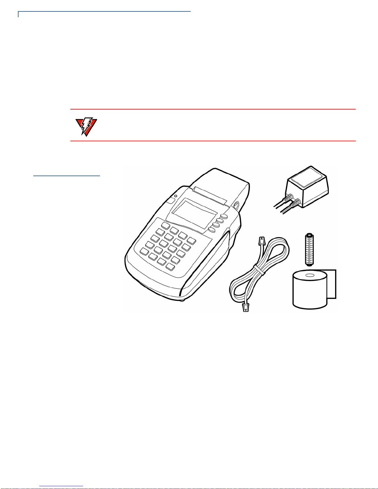
Unpack the Shipping Carton. . . . . . . . . . . . . . . . . . . . . . . . . . . . . . . . . . . . . . . . 10
Examine Terminal Features . . . . . . . . . . . . . . . . . . . . . . . . . . . . . . . . . . . . . . . . 11
Front Panel . . . . . . . . . . . . . . . . . . . . . . . . . . . . . . . . . . . . . . . . . . . . . . . . . . 11
Back Panel . . . . . . . . . . . . . . . . . . . . . . . . . . . . . . . . . . . . . . . . . . . . . . . . . . 12
Establish Telephone Line Connections . . . . . . . . . . . . . . . . . . . . . . . . . . . . . . . 13
Direct Connection . . . . . . . . . . . . . . . . . . . . . . . . . . . . . . . . . . . . . . . . . . . . . 13
Pass-Through Connection . . . . . . . . . . . . . . . . . . . . . . . . . . . . . . . . . . . . . . 13
Optional Swivel Stand. . . . . . . . . . . . . . . . . . . . . . . . . . . . . . . . . . . . . . . . . . 14
Install Paper Roll . . . . . . . . . . . . . . . . . . . . . . . . . . . . . . . . . . . . . . . . . . . . . . . . 14
Connect Optional Device(s) . . . . . . . . . . . . . . . . . . . . . . . . . . . . . . . . . . . . . . . . 17
Connect PIN Pad, Smart Card Reader, or Bar Code Wand. . . . . . . . . . . . . 17
Connect Check Reader. . . . . . . . . . . . . . . . . . . . . . . . . . . . . . . . . . . . . . . . . 18
External Printers Supported . . . . . . . . . . . . . . . . . . . . . . . . . . . . . . . . . . . . . 18
Connect Terminal Power Pack. . . . . . . . . . . . . . . . . . . . . . . . . . . . . . . . . . . . . . 19
Perform Power-On Printer Test . . . . . . . . . . . . . . . . . . . . . . . . . . . . . . . . . . . . . 20
Use Magnetic Card Reader . . . . . . . . . . . . . . . . . . . . . . . . . . . . . . . . . . . . . . . . 21
CHAPTER 3
Specifications Power . . . . . . . . . . . . . . . . . . . . . . . . . . . . . . . . . . . . . . . . . . . . . . . . . . . . . . . . . 23
Power Pack . . . . . . . . . . . . . . . . . . . . . . . . . . . . . . . . . . . . . . . . . . . . . . . . . . . . 23
Temperature. . . . . . . . . . . . . . . . . . . . . . . . . . . . . . . . . . . . . . . . . . . . . . . . . . . . 23
External Dimensions. . . . . . . . . . . . . . . . . . . . . . . . . . . . . . . . . . . . . . . . . . . . . . 23
Weight . . . . . . . . . . . . . . . . . . . . . . . . . . . . . . . . . . . . . . . . . . . . . . . . . . . . . . . . 23
CHAPTER 4
Maintenance Clean the Terminal. . . . . . . . . . . . . . . . . . . . . . . . . . . . . . . . . . . . . . . . . . . . . . . 25
Clean the Printer. . . . . . . . . . . . . . . . . . . . . . . . . . . . . . . . . . . . . . . . . . . . . . . . . 25

4INSTALLATION GUIDE
CHAPTER 5
VeriFone Service
and Support Return a Terminal for Service. . . . . . . . . . . . . . . . . . . . . . . . . . . . . . . . . . . . . . . 27
Accessories and Documentation . . . . . . . . . . . . . . . . . . . . . . . . . . . . . . . . . . . . 29
Power Pack. . . . . . . . . . . . . . . . . . . . . . . . . . . . . . . . . . . . . . . . . . . . . . . . . . 29
Thermal Printer Paper. . . . . . . . . . . . . . . . . . . . . . . . . . . . . . . . . . . . . . . . . . 29
Paper Roll Spindle . . . . . . . . . . . . . . . . . . . . . . . . . . . . . . . . . . . . . . . . . . . . 29
VeriFone Cleaning Kit. . . . . . . . . . . . . . . . . . . . . . . . . . . . . . . . . . . . . . . . . . 29
Download Cables . . . . . . . . . . . . . . . . . . . . . . . . . . . . . . . . . . . . . . . . . . . . . 29
Cables for Optional Peripherals . . . . . . . . . . . . . . . . . . . . . . . . . . . . . . . . . . 29
Telephone Line Cord . . . . . . . . . . . . . . . . . . . . . . . . . . . . . . . . . . . . . . . . . . 30
Terminal Swivel Stand Kit. . . . . . . . . . . . . . . . . . . . . . . . . . . . . . . . . . . . . . . 30
Pigtail Cables for Terminals with Swivel Stand. . . . . . . . . . . . . . . . . . . . . . . 30
Documentation . . . . . . . . . . . . . . . . . . . . . . . . . . . . . . . . . . . . . . . . . . . . . . . 30
CHAPTER 6
Troubleshooting
Guidelines Blank Display . . . . . . . . . . . . . . . . . . . . . . . . . . . . . . . . . . . . . . . . . . . . . . . . . . . 31
Terminal Does Not Dial Out . . . . . . . . . . . . . . . . . . . . . . . . . . . . . . . . . . . . . . . . 32
Printer Does Not Print. . . . . . . . . . . . . . . . . . . . . . . . . . . . . . . . . . . . . . . . . . . . . 32
Peripheral Device Does Not Work . . . . . . . . . . . . . . . . . . . . . . . . . . . . . . . . . . . 32
Keypad Does Not Respond . . . . . . . . . . . . . . . . . . . . . . . . . . . . . . . . . . . . . . . . 33
Transactions Fail To Process. . . . . . . . . . . . . . . . . . . . . . . . . . . . . . . . . . . . . . . 33
Check Magnetic Card Reader . . . . . . . . . . . . . . . . . . . . . . . . . . . . . . . . . 33
Check Telephone Line. . . . . . . . . . . . . . . . . . . . . . . . . . . . . . . . . . . . . . . 33
Telephone Line Connection Problems . . . . . . . . . . . . . . . . . . . . . . . . . . . . . . . . 34

INSTALLATION GUIDE 5
PREFACE
This guide is the primary source of information for setting up and installing the
Omni 3200SE/3210SE terminal.
Audience This guide is useful for anyone installing and configuring the Omni 3200SE/3210SE
terminal. Basic description of the terminal features are also provided.
Organization This guide is organized as follows:
Chapter 1, Terminal Overview. Provides an overview of the Omni 3200SE/3210SE
terminal.
Chapter 2, Terminal Setup. Explains how to set up and install the Omni 3200SE/
3210SE terminal. It tells how to select a location, establish power and telephone
line connections, and how to configure optional peripheral devices.
Chapter 3, Specifications. Discusses power requirements and dimensions of the
Omni 3200SE/3210SE terminal.
Chapter 4, Maintenance. Explains how to maintain Omni 3200SE/3210SE
terminals.
Chapter 5, VeriFone Service and Support. Provides information on contacting
your local VeriFone representative or service provider, and information on how to
order accessories or documentation from VeriFone.
Chapter 6, Troubleshooting Guidelines. Provides troubleshooting guidelines, for
common problems encountered in terminal installation and configuration.
Related
Documentation To learn more about the Omni 3200SE/3210SE terminal, refer to the following set
of documents, and their associated VeriFone Part Number (VPN):
•
Omni 3200SE/3210SE Certifications and Regulations
, VPN - 22874
•
Omni 3200SE/3210SE Quick Installation Guide
, VPN - 22875
•
Omni 3200SE/3210SE Installation Guide
, VPN - 22876
•
Omni 3200SE/3210SE Programmers Guide
, VPN - 22877
•
Omni 3200SE/3210SE Reference Guide
, VPN - 22878
•
Omni 3200SE/3210SE Stand Quick Installation Guide
, VPN - 22880

PREFACE
Conventions Used in This Guide
6INSTALLATION GUIDE
Conventions
Used in This
Guide
Various conventions are used to help quickly identify special formatting. Table 1
describes these conventions and provides examples of their use.
Table 1 Document Conventions
Convention Meaning Example
Blue Text in blue indicates terms that are cross
referenced. See Conventions Used in This Guide.
Italics Italic typeface indicates book titles or
emphasis. You
must
install a roll of thermal-sensitive
paper in the printer.
ScreenText - PRE ScreenText format is used while specifying
onscreen text, such as text that would be
entered at a command prompt, or to provide
an URL.
http://www.verifone.com
The pencil icon is used to highlight important
information. RS232-type devices do not work with the
PIN pad port.
The caution symbol indicates hardware or
software failure, or loss of data. The terminal is not waterproof or
dustproof, and is intended for indoor use
only.
The lighting symbol is used as a warning
when bodily injury might occur. Due to risk of shock do not use the
terminal near water.
NOTE
CAUTION
WARNING

INSTALLATION GUIDE 7
CHAPTER 1
Terminal Overview
The Omni 3200SE/3210SE terminal is an electronic transaction terminal capable of
gathering and transferring information at high speed. The attractive, ergonomic
design delivers power and usability in a convenient countertop design that offers
versatility, reliability, and low cost of ownership.
Figure 1 Omni 3200SE/3210SE Point-of-Sale Terminal
The Omni 3200SE/3210SE terminal supports many different kinds of business
applications, including:
•Electronic Point-of-Sale (POS) payment transfer and authorization
•Credit, debit, and ATM card transactions
•Check processing
•Electronic benefit transfers and value-added applications
•Inventory and process tracking

TERMINAL OVERVIEW
Features and Benefits
8INSTALLATION GUIDE
Features and
Benefits Omni 3200SE/3210SE terminals provide the right combination of features and
functions at the right price.
•Bold design is sleek, stylish, and compact for convenient countertop use.
•Intuitive ATM-style interface, large 8 line x 21 character backlit display with
split screen capabilities, large keys, and extra-size menu prompts simplify
training and reduce calls to the Help Desk.
•Quiet, fast integrated high-speed thermal printer simplifies paper loading and
virtually eliminates paper jams.
•Triple-track, high-coercivity card reader handles most magnetic stripe cards.
•Dual telephone ports eliminate the expense of a second phone line.
•Industry-best warranty ensures uncompromising reliability from VeriFone, the
worldwide leader in e-payment.
•Comprehensive line of VeriFone peripherals, including check readers, smart
card readers, bar code wands, and even external PIN pads, supports almost
any type of point-of-sale transaction.
Internal
PIN Pad VeriFone’s Omni 3210SE expands on the Omni 3200SE terminal’s capabilities with
the addition of an internal PIN pad for processing debit, electronic benefits
transfer (EBT), and other PIN-based transactions. This internal PIN pad meets
published 3DES standards for DUKPT and Master/Session key management
schemes and eliminates the need to purchase and connect an external PIN pad,
and also saves valuable countertop space. To help ensure the security of PIN-
based transactions, the Omni 3210SE incorporates advanced fraud protection and
tamper-resistant features, in addition to widely-used data encryption methods and
key management schemes.

INSTALLATION GUIDE 9
CHAPTER 2
Terminal Setup
This chapter describes the terminal setup procedure. You will learn how to:
•Select a location and protect the terminal from adverse Environmental
Factors. See Select Terminal Location.
•Unpack the shipping carton. See Unpack the Shipping Carton.
•Examine terminal features. See Examine Terminal Features.
•Establish telephone line connections. See Establish Telephone Line
Connections.
•Install paper roll in the printer. See Install Paper Roll.
•Configure optional peripheral devices. See Connect Optional Device(s).
•Establish power connections. See Connect Terminal Power Pack.
•Conduct credit/debit transactions. See Use Magnetic Card Reader.
Select Terminal
Location Use the following guidelines to select a location for the Omni 3200SE/3210SE
terminal.
Ease of Use • Select a location convenient for both merchant and cardholder.
•Select a flat support surface, such as a countertop or table.
•Select a location near a power outlet and a telephone/modem line connection.
For safety, do not string the power cable in a walkway or place across a
walkway on the floor.
Environmental
Factors •Do not use the terminal where there is high heat, dust, humidity, moisture, or
caustic chemicals or oils.
•Keep the terminal away from direct sunlight and anything that radiates heat,
such as a stove or a motor.
•Do not use the terminal outdoors.
NOTE When using the Omni 3200SE/3210SE terminal with the optional swivel stand,
make sure there is enough space on the countertop or table so that the terminal
can rotate freely.
CAUTION The terminal is not waterproof or dustproof, and is intended for indoor use only.
Any damage to the unit from exposure to rain or dust can void any warranty.

TERMINAL SETUP
Unpack the Shipping Carton
10 INSTALLATION GUIDE
Electrical
Considerations •Avoid using this product during electrical storms.
•Avoid locations near electrical appliances or other devices that cause
excessive voltage fluctuations or emit electrical noise (for example, air
conditioners, electric motors, neon signs, high-frequency or magnetic security
devices, or computer equipment).
•Do not use the terminal near water or in moist conditions.
Unpack the
Shipping
Carton
Open the shipping carton and carefully inspect its contents for possible shipping
damage.
Figure 2 Omni 3200SE/3210SE Product Components
1Remove and inspect the following items (see Figure 2):
•Omni 3200SE/3210SE terminal
•Power pack and attached cables
•Telephone line cord
•Roll of thermal printer paper
•Plastic spindle roll
2Remove all plastic wrapping from the terminal and other components.
3Remove the clear protective film from the LCD screen.
WARNING Due to risk of shock or terminal damage, do not use the terminal near water,
including a bathtub, wash bowl, kitchen sink or laundry tub, in a wet basement, or
near a swimming pool.

TERMINAL SETUP
Examine Terminal Features
INSTALLATION GUIDE 11
4Save the shipping carton and packing material for future repacking or moving
the terminal.
Examine
Terminal
Features
Before continuing the installation process, notice the features of the Omni 3200SE/
3210SE terminal (see Figure 3).
Figure 3 Omni 3200SE/3210SE Terminal Features (Front Panel)
Front Panel The front panel includes the following features:
•An LCD screen.
•Four types of keys:
•A 12-key, telephone-style keypad.
•Four ATM-style function keys, labeled F1 to F4, to the right of the LCD
screen.
•Four unlabeled, programmable function keys above the keypad.
•Three color-coded function keys to the right of the keypad.
•An ALPHA key to the right of the keypad.
WARNING Do not use a terminal that has been damaged or tampered with.
The Omni 3200SE/3210SE terminal is a secure product and any tampering can
cause the terminal to cease to function properly. The terminal comes equipped
with tamper-evident labels that indicate if the terminal case has been opened.
If a label or component appears damaged, please notify the shipping company
and your VeriFone representative or service provider immediately.
LCD SCREEN
TELEPHONE-STYLE KEYPAD
PROGRAMMABLE FUNCTION KEYS
ATM-STYLE FUNCTION KEYS
MAGNETIC CARD READER
INTERNAL THERMAL
LED INDICATOR
CONNECTION PORTS
(BACK PANEL)
COLOR-CODED FUNCTION KEYS
PRINTER
PAPER ROLL COVER RELEASE
ALPHA KEY
PAPER FEED BUTTON

TERMINAL SETUP
Examine Terminal Features
12 INSTALLATION GUIDE
•A magnetic card reader, built into the right side. The icon at right
shows the proper swipe direction, with the stripe down and facing
inward, toward the keypad.
•A colored LED (Light Emitting Diode) indicator with the following states:
•Steady green indicates power is ON.
•Slow flashing green (roughly one flash per second) indicates no paper in
the printer.
•Fast flashing green (roughly two flashes per second) indicates a printer
mechanism error.
•Flashing red indicates the terminal is downloading printer-related files.
•An internal thermal printer.
•A paper roll cover release button.
•A paper feed button.
Back Panel Turn the terminal around to view the back panel with the connection ports, under
the paper roll case. Notice the different ports used to connect the Omni 3200SE/
3210SE teminal to a communications line, optional peripheral devices, and the
power supply (see Figure 4).
Figure 4 Connection Ports (Back Panel)
•Two RJ-11 modular phone jacks can be used to connect the Omni 3200SE/
3210SE terminal to a telephone line:
•One port can be identified by a Telco icon, shown at right. Use
this port to connect the Omni 3200SE/3210SE terminal directly to
a modular telephone wall jack (refer to Direct Connection).
•The other port can be identified by a by a Telset icon, shown at
right.Use this port to connect a telephone to the terminal (refer to
Pass-Through Connection).
NOTE VeriFone ships different variants of the Omni 3200SE/3210SE terminal for different
markets. Your terminal may have a different configuration than the terminal shown
in this guide, but the basic processes remain the same, regardless of terminal
configuration.

TERMINAL SETUP
Establish Telephone Line Connections
INSTALLATION GUIDE 13
•Two MOD10 modular jacks can be used to connect optional peripheral
devices.
•Use the RS232 port, icon shown at right, to connect a VeriFone
CR 600 check reader or other peripheral device.
•Use the bar code and PIN pad port, icons shown at right, to
connect a PIN pad, smart card reader, or bar code wand.
•The power connection portuses a round barrel connector witha lock
notch (see Figure 12) to securely connect the terminal to a power
source. This port is identified by the electrical power icon shown at
right.
Establish
Telephone Line
Connections
The Omni 3200SE/3210SE terminal can be connected to a telephone line in one of
two ways: direct or pass-through. The relative advantages and disadvantages of
these two types of telephone connections are described below.
Direct Connection Connect the telephone cord to the communication port on the terminal, then route
it directly to a telephone wall jack (see Figure 5). With a direct connection, the
phone line is dedicated to the terminal, making it possible to perform an electronic
transaction at any time.
Figure 5 Direct Connection
Pass-Through
Connection Connect the telephone cord to the Telset port on the terminal, then route it to the
RJ-11 jack on a standard telephone (see Figure 6). With a pass-through
connection, the telephone can be used when the terminal is not attempting to
perform a transaction.
WARNING Do not connect the terminal to the power supply until all the peripherals are
attached.
CAUTION Do not string the telephone cord across a walkway or place it so as to interfere in
high-traffic areas.
To reduce the risk of fire, use only No. 26AWG or larger telecommunication line
cord.

TERMINAL SETUP
Install Paper Roll
14 INSTALLATION GUIDE
Figure 6 Pass-Through Connection
A pass-through telephone line connection can save the cost of an additional
dedicated or leased line, but there are several disadvantages to using a pass-
through connection:
•Normal calls cannot be made while the terminal is processing a transaction, or
when a remote host computer is dialing in to the terminal.
•Lifting thetelephone handset during a transaction can disrupt the audible data
carrier signal and cause the terminal transaction to fail.
Optional Swivel
Stand VeriFone produces an optional swivel stand for Omni 3200SE/3210SE terminals
Some terminals come with the swivel stand already attached, with two pre-
installed “pigtail” cables to allow convenient connection of the power cable and
telephone line cord without removing the swivel stand.
To set up a direct connection using the pigtail cable:
•Insert the connector on one end of the telephone line cord into the modular
RJ-11 female jack on the end of the telephone line pigtail.
•Insert the connector on the other end of the cord into a nearby RJ-11
telephone wall jack.
•To configure a pass-through connection for a terminal with attached swivel
stand, the stand must be removed, then re-attached. The procedure for
removing and reattaching the swivel stand is described in the
Omni 3200SE/
3210SE Stand Quick Installation Guide
, (VPN - 22880).
Install Paper
Roll A fast, quiet thermal printer is built-in to the Omni 3200SE/3210SE terminal.
Before processing transactions that require a receipt or record, you
must
install a
roll of thermal-sensitive paper in the printer.

TERMINAL SETUP
Install Paper Roll
INSTALLATION GUIDE 15
The Omni 3200SE/3210SE printer uses a roll of single-ply, thermal-sensitive paper
58 millimeters (2.25 inches) wide and approximately 25-33 meters (82-108 feet)
long.
To Install a Paper Roll
1Turn on the terminal. The LED indicator willblink on and off, indicating that the
printer needs paper.
2Press the button on the side of the terminal to unlatch the paper roll cover,
then rotate the cover up and back (see Figure 7).
Figure 7 Printer Roll Cover Release Button
3If present, remove a partial roll of paper from the printer tray by lifting it out.
4For new rolls of paper, loosen the glued leading edge of the paper or remove
the protective strip.
5Hold the roll so the paper feeds from the
bottom
of the roll.
6Optionally, insert the orange plastic spindle into the paper roll.
7Place the paper roll into the paper roll cradle (see Figure 8).
WARNING Low-quality paper may cause the printer to operate poorly. To order high-quality
VeriFone paper, refer to Accessories and Documentation.
CAUTION Store thermal paper in a dry, dark area. Handle thermal paper carefully: impact,
friction, temperature, humidity, and oils affect the color and storage characteristics
of the paper.
Never load a roll of paper with folds, wrinkles, tears, or holes at the edges or in the
print area.

TERMINAL SETUP
Install Paper Roll
16 INSTALLATION GUIDE
Figure 8 Loading Paper Roll
8Close the paper roll cover by gently pressing directly on the cover until it clicks
shut. Allow a small amount of paper to extend outside the cover (see
Figure 9).
Figure 9 Closing Paper Roll Cover
For paper ordering information, refer to Accessories and Documentation.
NOTE To prevent damage to the print roller on the paper roll cover, always close the
cover by gently pressing down on the paper roll cover.

TERMINAL SETUP
Connect Optional Device(s)
INSTALLATION GUIDE 17
Connect
Optional
Device(s)
The Omni 3200SE/3210SE terminal supports many peripheral devices designed
for use with electronic point-of-sale terminals. Use the two communication ports
on the back panel to connect up to two optional devices. To order cables to
connect peripheral devices, refer to Accessories and Documentation.
The following sections discuss the most common optional devices supported by
this terminal.
Other optional devices may be supported. For more information, please contact
your VeriFone distributor.
Connect PIN Pad,
Smart Card
Reader, or Bar
Code Wand
To Connect PIN Pad, Smart Card Reader, or Bar Code Wand
1If necessary, insert the small modular plug on one end of the PIN pad cable
into the PIN pad’s modular jack.
For a bar code wand, connect the converter cable (VPN - 07411-xx) to the bar
code wand cable.
2If installing a PINpad 101, PINpad 201 or PINpad 1000, position and insert the
grommet to secure the cable connection.
If a cable is not already connected to the smart card reader or PINpad 501,
insert the small modular plug on one end of the interface cable into the
optional device’s modular jack.
3Insert the larger MOD10 connector on the other end of the PIN pad cable into
the PIN pad port on the terminal’s back panel.
CAUTION Before connecting any peripheral device, remove the power cord from the back of
the terminal and be sure the LED indicator is not lit. Reconnect the power cord
only
after
finishing connection of peripheral device(s).
For complete information about peripheral installation and use, refer to the user
documentation supplied with those devices.
Table 2 Optional Devices Supported
Optional Device Connection Port
Bar code PIN pad
CR 600 RS232
Console PIN pad
External LAN RS232
PIN pad PIN pad
RS232 Electronic Cash Register RS232
NOTE RS232-type devices do not work with the PIN pad port; PIN pad-type devices do
not work with the RS232 port. If an optional peripheral device does not function
correctly, check the port connection.

TERMINAL SETUP
Connect Optional Device(s)
18 INSTALLATION GUIDE
Figure 10 provides an example of connecting a PINpad 1000 to the Omni
3200SE/3210SE terminal.
Figure 10 PINpad 1000 Connection
Connect Check
Reader The Omni 3200SE/3210SE terminal supports the CR 600 and CR 1000
i
VeriFone
check readers. Contact your VeriFone representative or visit the online store at
www.store.verifone.com for information on these devices. Figure 11 provides
an example of a peripheral connection to an RS232 port.
Figure 11 CR 600 Check Reader Connection
External Printers
Supported Though the Omni 3200SE/3210SE terminal has an internal thermal printer, it may
be more convenient to print larger print runs (for example, daily or weekly reports)
to an external printer.
CAUTION Check readers require a separate power source. Before connecting a check
reader or similar device, remove the power cord from the back of the terminal and
be sure the LED indicator is not lit.

TERMINAL SETUP
Connect Terminal Power Pack
INSTALLATION GUIDE 19
The Omni 3200SE/3210SE terminal supports the P250, P350,P900, and P950
VeriFone external printers. Contact your VeriFone representative or visit the
online store at www.store.verifone.com for information on these devices.
External printer connections are through the same port as check readers (see
Figure 11).
Connect Terminal
Power Pack
When finished connecting optional peripheral(s), connect the Omni 3200SE/
3210SE terminal to a power source.
1Insert the round barrel connector (see Figure 12) into the power port,
identified by the icon at right.
aTo lock the connector into the power port, align the plastic lock tab so it
points up. Insert the connector and twist to the left.
bTo unlock the connector, twist it to the right.
2Plug the power pack cable into a wall outlet or surge protector.
Figure 12 Omni 3200SE/3210SE Power Pack Connection
NOTE To connecta Printer 250,a custom interface cable isrequired. VeriFone publishes
the specifications for this cable in the
Omni 3200SE/3210SE Reference Manual
(VPN - 22878).
CAUTION Using an incorrectly rated power supply can damage the terminal or cause it not
to work as specified. Before connecting, ensure that the power supply being used
to power the terminal matches the requirements specified at the back of the
terminal. (see Chapter 3, Specifications, for detailed power supply specifications).
Obtain the appropriately rated power supply before continuing.
NOTE The round barrel connector on the power pack cable has a plastic lock tab that
secures the power cable to the terminal.

TERMINAL SETUP
Perform Power-On Printer Test
20 INSTALLATION GUIDE
When the terminal has power, the LCD screen lights and the LED indicator
flashes on and off if the printer has no paper, or remains lit if there is paper
loaded.
If an application is loaded in the terminal, it starts after the initial VeriFone
copyright screen and displays a unique copyright screen. If no application is
loaded in the terminal, DOWNLOAD NEEDED appears on screen after the initial
VeriFone copyright screen.
Perform Power-
On Printer Test After installing a paper roll, perform a quick test to make sure the thermal printer is
operating correctly:
1Temporarily disconnect the terminal from its power source by removing the
power connector from the power port on the back panel (see Figure 12).
2Press and hold down the paper feed button, then insert the power connector
into the power port. The printer test starts automatically, and then stops after a
few seconds.
3When the Omni 3200SE/3210SE terminal initiates its test printout, release the
paper feed button. The complete test printout shows printer information and
repeating character strings of various sizes.
4After completing the power-on printer test, press the paper feed button to
advance the paper roll a few centimeters (about an inch), then tear off the
printout using the serrated metal tear strip.
WARNING Do not plug the power pack into an outdoor outlet or operate the terminal
outdoors. Also, disconnecting power during a transaction can cause transaction
data files not yet stored in terminal memory to be lost.
NOTE To protect against possible damage caused by lightning strikes and electrical
surges, consider installing a power surge protector.
This manual suits for next models
1
Table of contents
Other VeriFone Credit Card Machine manuals

VeriFone
VeriFone MX800 Series User manual

VeriFone
VeriFone HICAPS VX680 User manual

VeriFone
VeriFone HICAPS VX820 User manual

VeriFone
VeriFone VX-670 series User manual

VeriFone
VeriFone VX 675 Series User manual

VeriFone
VeriFone Omni 3730 User manual

VeriFone
VeriFone MX800 Series Parts list manual

VeriFone
VeriFone C680 FF User manual

VeriFone
VeriFone VX 805 User manual

VeriFone
VeriFone HICAPS VX680 User manual