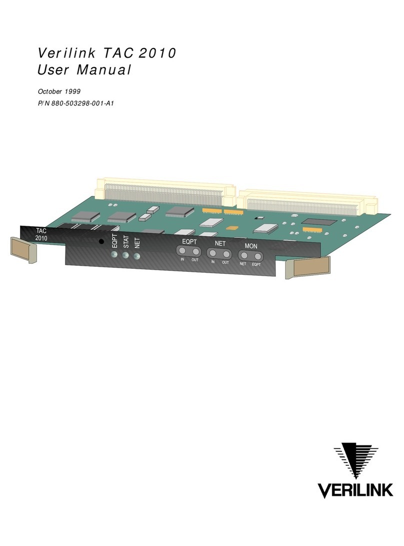
Verilink PRISM 4051 User manual

Copyright Notice
Copyright © 1999 Verilink Corporation. All rights reserved.
This document does not create any express or implied warranty about Verilink or about its prod-
ucts or services. Verilink’s sole warranty is contained in its product warranty. The end-user docu-
mentation is shipped with Verilink’s products and constitutes the sole specifications referred to in
the product warranty. Verilink has made reasonable efforts to verify that the information contained
herein is accurate, but Verilink assumes no responsibility for its use or for any infringement of pat-
ents or other rights of third parties that may result. The customer is solely responsible for verifying
the suitability of Verilink’s products for its use. Specifications are subject to change without notice.
Manual reorder # 34-00253
2nd Edition, June 1999
Trademarks
Verilink is a registered trademark Verilink Corporation.
Any named products herein are trademarks of their respective companies.
FCC Requirements
This equipment has been tested and found to comply with the limits for a Class A digital device,
pursuant to Part 15 of FCC Rules. These limits are designed to provide reasonable protection
against harmful interference when the equipment is operated in a commercial environment. This
equipment generates, uses, and can radiate radio frequency energy and if not installed and used in
accordance with the instruction manual, may cause harmful interference to radio communications.
Operation of this equipment in a residential area is likely to cause harmful interference in which
case the user is required to correct the interference at his own expense. This device must also
accept any interference received, including interference that may cause undesired operation.
Shielded cables must be used to ensure compliance with the Class A FCC limits.
Changes or modifications to this unit not expressly approved by the party responsi-
ble for compliance could void the user’s authority to operate the equipment.
This equipment complies with Part 68 of the FCC Rules.
1 All direct connections to DDS lines must be
made using standard plugs and jacks (compli-
ant with Part 68). The table presents a list of
applicable registration jack USOCs, facility interface codes (FICs), and service order codes
(SOCs). These are required when ordering service from the telco.
2 If the CSU/DSU appears to be malfunctioning, it should be disconnected from the DDS lines
until the source of trouble is determined to be your equipment or the telephone line. If your
equipment needs repair, it should not be reconnected until it is repaired.
3 The CSU/DSU has been designed to prevent harm to the DDS network. If the telephone com-
pany finds that the equipment is exceeding tolerable parameters, it can temporarily disconnect
service. In this case, the telephone company will give you advance notice, if possible.
4 Under FCC rules, no customer is authorized to repair this equipment, regardless of warranty
status.
5 If the telephone company alters its equipment in a manner that will affect the use of this device,
it must give you advance warning so that you can have the opportunity for uninterrupted service.
You will be advised of your right to file a complaint with the FCC.
6 In the event of equipment malfunction, all repairs should be performed by our company or an
authorized agent. It is the responsibility of users requiring service to report the need for service
to our company or to one of our authorized agents.
Port ID REN/SOC FIC USOC
56 kbps 6.0F 04DU5-56 RJ-48S

7 On the side of the 1051 chassis is a label that contains, among other information, FCC registra-
tion number for this equipment. If requested, this information must be provided to the telephone
company.
Canadian Emissions Requirements
This digital apparatus does not exceed the Class A limits for radio noise emissions from digital
apparatus set out in the Radio Interference Regulations of the Canadian Department of Communi-
cations.
On 48-VDC units only, end users should use existing 48-VDC battery sources or
a CSA-certified power supply.
Le présent appareil numérique n’émet pas de bruits radioélectriques dépassant les limites applica-
bles aux appareils numériques (de la class A) prescrites dans le Règlement sur le brouillage
radioélectrique édicté par le ministère des Communications du Canada.
Notice: The Industry Canada label identifies certified equipment. This certification means that the
equipment meets certain telecommunications network protective, operational, and safety require-
ments. The Industry Canada does not guarantee the equipment will operate to the user’s
satisfaction.
Before installing this equipment, users should ensure that it is permissible to be connected to the
facilities of the local telecommunications company. The equipment must also be installed using an
acceptable method of connection. In some cases, the company’s inside wiring associated with a
single line individual service may be extended by means of a certified connector assembly (tele-
phone extension cord). The customer should be aware that compliance with the above conditions
may not prevent degradation of service in some situations.
Repairs to certified equipment should be made by an authorized Canadian maintenance facility
designated by the supplier. Any repairs or alterations made by the user to this equipment, or equip-
ment malfunctions, may give the telecommunications company cause to request the user to discon-
nect the equipment.
Users should ensure for their own protection that the electrical ground connections of the power
utility, telephone lines, and internal metallic water pipe system, if present, are connected together.
This precaution may be particularly important in rural areas.
Caution: Users should not attempt to make such connections themselves, but should contact the
appropriate electric inspection authority, or electrician, as appropriate.
Warranty
Verilink's product warranty covers repair or replacement of all equipment under normal use for a
five-year period from date of shipment. Replacement products may be new or reconditioned. Any
replaced or repaired product or part has a ninety (90) day warranty or the remainder of the initial
warranty period, whichever is longer. Our in-house Repair Center services on a standard 10-work-
day-turnaround basis.
Customer Service
Verilink offers the following services:
• System Engineers at regional sales offices for network design and planning assistance
(800) 837-4546
• Technical Assistance Center for free 24×7 telephone support during installation, maintenance, and
troubleshooting at (800) 285-2755 and support@verilink.com
• Return Materials Authorization (RMA) (800) 926-0085, ext. 2282
• Maintenance contracts and leasing plans (800) 837-4546, ext. 206
• Technical Training on network concepts and Verilink products at (800) 837-4546,
ext. 346 and training@verilink.com
✍

• Web site at www.verilink.com
• FAX-On-Demand at (800) 957-5465
Returning Products
A product must be assigned a Return Materials Authorization (RMA) number before it is sent to
Verilink for repair. An RMA number is issued by Verilink Customer Service at (800) 926-0085.
ext. 2282.
Safety Precautions
When handling this equipment, follow these basic safety precautions to reduce the risk of electric
shock and injury:
• Follow all warnings and instructions marked on the product and in the manual.
• Unplug the hardware from the wall outlet before cleaning. Do not use liquid cleaners or aerosol
cleaners. Use a slightly damp cloth for cleaning.
• Do not place this product on an unstable cart, stand, or table. It may fall, causing serious damage to
the product.
• This product should be operated only from the type of power source indicated on the marking label
and manual. If you are unsure of the type of power supply you are using, consult your dealer or local
power company.
• Do not allow anything to rest on the power cord. Do not locate this product where the cord interferes
with the free movement of people.
• Do not overload wall outlets and extension cords, as this can result in fire or electric shock.
• Never push objects of any kind into the unit. They may touch dangerous voltage points or short out
parts that could result in fire or electric shock. Never spill liquid of any kind on this equipment.
• Unplug the equipment from the wall outlet and refer servicing to qualified service personnel under
the following conditions:
• When the power supply cord or plug is damaged or frayed.
• If liquid has been spilled into the product.
• If the product has been exposed to rain or water.
• If the product has been dropped or if the housing has been damaged.

v
Table of Contents
Copyright Notice. . . . . . . . . . . . . . . . . . . . . . . . . . . . . . . . ii
Trademarks . . . . . . . . . . . . . . . . . . . . . . . . . . . . . . . . . . . . ii
FCC Requirements. . . . . . . . . . . . . . . . . . . . . . . . . . . . . . ii
Canadian Emissions Requirements . . . . . . . . . . . . . . . . . .iii
Warranty . . . . . . . . . . . . . . . . . . . . . . . . . . . . . . . . . . . . . .iii
Customer Service . . . . . . . . . . . . . . . . . . . . . . . . . . . . . . .iii
Returning Products . . . . . . . . . . . . . . . . . . . . . . . . . . . . . .iv
Safety Precautions. . . . . . . . . . . . . . . . . . . . . . . . . . . . . . .iv
1 General
Introduction . . . . . . . . . . . . . . . . . . . . . . . . . . . . . . . . . . . . 1
Features . . . . . . . . . . . . . . . . . . . . . . . . . . . . . . . . . . . . . . . 2
Specifications . . . . . . . . . . . . . . . . . . . . . . . . . . . . . . . . . . 2
Network Interface . . . . . . . . . . . . . . . . . . . . . . . . . . . 2
Equipment
Interface . . . . . . . . . . . . . . . . . . . . . . . . . . . . . . . . . . 2
Diagnostics. . . . . . . . . . . . . . . . . . . . . . . . . . . . . . . . . 2
Management
Interfaces . . . . . . . . . . . . . . . . . . . . . . . . . . . . . . . . . 2
. . . . . . . . . . . . . . . . . Supervisory (SUPV) Port2
Power . . . . . . . . . . . . . . . . . . . . . . . . . . . . . . . . . . . . . 2
Mechanical. . . . . . . . . . . . . . . . . . . . . . . . . . . . . . . . . 3
Environmental . . . . . . . . . . . . . . . . . . . . . . . . . . . . . . 3
Compatibility . . . . . . . . . . . . . . . . . . . . . . . . . . . . . . . 3
Industry Listings . . . . . . . . . . . . . . . . . . . . . . . . . . . . 3
Ordering
Numbers . . . . . . . . . . . . . . . . . . . . . . . . . . . . . . . . . . . . . . 4
2 Installation
Safety Summary . . . . . . . . . . . . . . . . . . . . . . . . . . . . . . . . 5
Unpacking and Inspection. . . . . . . . . . . . . . . . . . . . . . . . . 5
Supplied
Materials . . . . . . . . . . . . . . . . . . . . . . . . . . . . . . . . . . . . . . 5
Mounting . . . . . . . . . . . . . . . . . . . . . . . . . . . . . . . . . . . . . . 5
Unit Configuration . . . . . . . . . . . . . . . . . . . . . . . . . . . . . . 6
Configuration
Switch S1 . . . . . . . . . . . . . . . . . . . . . . . . . . . . . . . . 6
Boot Mode . . . . . . . . . . . . . . . . . . . . . . . . . . . . . 7
DDS Mode . . . . . . . . . . . . . . . . . . . . . . . . . . . . . 7
Timing Source. . . . . . . . . . . . . . . . . . . . . . . . . . . 7
RTS-to-CTS Delay . . . . . . . . . . . . . . . . . . . . . . 7
RTS, CTS, and DCD Handshake . . . . . . . . . . . . 7
Local and Remote Loopback Enable . . . . . . . . . 7
DTE Alarm . . . . . . . . . . . . . . . . . . . . . . . . . . . . . 8
Configuration Switch S2 . . . . . . . . . . . . . . . . . . . . . . 8
Antistream Timer . . . . . . . . . . . . . . . . . . . . . . . . 8
V.54 Loop Detection. . . . . . . . . . . . . . . . . . . . . . 8
Circuit Assurance . . . . . . . . . . . . . . . . . . . . . . . . 8
Loop Mode . . . . . . . . . . . . . . . . . . . . . . . . . . . . . 8
SUPV Port Rate . . . . . . . . . . . . . . . . . . . . . . . . . 9
NMS Port Rate . . . . . . . . . . . . . . . . . . . . . . . . . . .9
Configuration Switch S3 . . . . . . . . . . . . . . . . . . . . . . .9
Force Download Mode. . . . . . . . . . . . . . . . . . . . .9
Address Switch S4. . . . . . . . . . . . . . . . . . . . . . . . . . . .9
Network
Management Connections. . . . . . . . . . . . . . . . . . . . . . . . .10
Supervisory (SUPV) Connections. . . . . . . . . . . . . . .10
NMS Port. . . . . . . . . . . . . . . . . . . . . . . . . . . . . . . . . .10
NMS IN and NMS OUT . . . . . . . . . . . . . . . . . .11
NMS Split Cable . . . . . . . . . . . . . . . . . . . . . . . .11
NMS IN Only. . . . . . . . . . . . . . . . . . . . . . . . . . .11
Chassis Operation. . . . . . . . . . . . . . . . . . . . . . . .11
Data Port Connections . . . . . . . . . . . . . . . . . . . . . . . . . . .12
Port Connections . . . . . . . . . . . . . . . . . . . . . . . . . . . .13
DDS NET. . . . . . . . . . . . . . . . . . . . . . . . . . . . . .13
Power Connection. . . . . . . . . . . . . . . . . . . . . . . . . . . . . . .14
Redundant
Power Source . . . . . . . . . . . . . . . . . . . . . . . . . . . . . .14
Single Power Source . . . . . . . . . . . . . . . . . . . . . . . . .14
3 Operation
Introduction. . . . . . . . . . . . . . . . . . . . . . . . . . . . . . . . . . . .17
Front Panel
Controls and Indicators . . . . . . . . . . . . . . . . . . . . . . . . . .17
General Status
Indicators . . . . . . . . . . . . . . . . . . . . . . . . . . . . . . . . . .17
Test Controls
and Indicators . . . . . . . . . . . . . . . . . . . . . . . . . . . . . .18
Alarm Controls
and Indicators . . . . . . . . . . . . . . . . . . . . . . . . . . . . . .18
Front Panel
Testing . . . . . . . . . . . . . . . . . . . . . . . . . . . . . . . . . . . . . . .18
Test Switch . . . . . . . . . . . . . . . . . . . . . . . . . . . . . . . .18
Supervisory Port . . . . . . . . . . . . . . . . . . . . . . . . . . . .20
Upgrading Software . . . . . . . . . . . . . . . . . . . . . . . . . . . . .20
4 Terminal Operation
Terminal Interface. . . . . . . . . . . . . . . . . . . . . . . . . . . . . . .21
Screen
Components. . . . . . . . . . . . . . . . . . . . . . . . . . . . . . .21
Device Type and Revision . . . . . . . . . . . . . . . . .21
Date/Time . . . . . . . . . . . . . . . . . . . . . . . . . . . . .22
Element ID . . . . . . . . . . . . . . . . . . . . . . . . . . . . .22
Menu Title . . . . . . . . . . . . . . . . . . . . . . . . . . . . .22
Near and Far Element. . . . . . . . . . . . . . . . . . . . .22
Messages . . . . . . . . . . . . . . . . . . . . . . . . . . . . . .22
Local/Remote Screen Indicator . . . . . . . . . . . . .22
Cursor Controls. . . . . . . . . . . . . . . . . . . . . . . . . . . . .22
Field Types . . . . . . . . . . . . . . . . . . . . . . . . . . . . . . . .22
Software Configuration. . . . . . . . . . . . . . . . . . . . . . . . . . .23

vi
Interface Start-up . . . . . . . . . . . . . . . . . . . . . . . . . . . 23
Menu Structure. . . . . . . . . . . . . . . . . . . . . . . . . . . . . 24
Alarms Screen . . . . . . . . . . . . . . . . . . . . . . . . . . . . . 24
NETAlarms. . . . . . . . . . . . . . . . . . . . . . . . . . . . 25
DTE Alarms . . . . . . . . . . . . . . . . . . . . . . . . . . . 25
(alarm status). . . . . . . . . . . . . . . . . . . . . . . . . . . 25
Reset Alarm Registers . . . . . . . . . . . . . . . . . . . 25
Maintenance Screen. . . . . . . . . . . . . . . . . . . . . . . . . 26
Clear Tests . . . . . . . . . . . . . . . . . . . . . . . . . . . . 26
Clear Alarms. . . . . . . . . . . . . . . . . . . . . . . . . . . 26
Loop . . . . . . . . . . . . . . . . . . . . . . . . . . . . . . . . . 26
Unloop . . . . . . . . . . . . . . . . . . . . . . . . . . . . . . . 26
Loop Mode . . . . . . . . . . . . . . . . . . . . . . . . . . . . 27
Line Loop. . . . . . . . . . . . . . . . . . . . . . . . . . 27
Data Loop . . . . . . . . . . . . . . . . . . . . . . . . . 27
Latching Loop . . . . . . . . . . . . . . . . . . . . . . 27
V.54 Loop . . . . . . . . . . . . . . . . . . . . . . . . . 27
Local Loop. . . . . . . . . . . . . . . . . . . . . . . . . 28
Activate Remote Access . . . . . . . . . . . . . . . . . . 28
BERT . . . . . . . . . . . . . . . . . . . . . . . . . . . . . . . . 29
Test Length . . . . . . . . . . . . . . . . . . . . . . . . . . . . 29
Pattern Sync . . . . . . . . . . . . . . . . . . . . . . . . . . . 29
Elapsed Time . . . . . . . . . . . . . . . . . . . . . . . . . . 29
Bit Errors. . . . . . . . . . . . . . . . . . . . . . . . . . . . . . 29
Errored Seconds . . . . . . . . . . . . . . . . . . . . . . . . 29
% EFS . . . . . . . . . . . . . . . . . . . . . . . . . . . . . . . . 29
Start Test. . . . . . . . . . . . . . . . . . . . . . . . . . . . . . 29
Reset Errors. . . . . . . . . . . . . . . . . . . . . . . . . . . . 29
NET and DTE Status . . . . . . . . . . . . . . . . . . . . 29
Near Loops . . . . . . . . . . . . . . . . . . . . . . . . . . . . 30
Far Loops . . . . . . . . . . . . . . . . . . . . . . . . . . . . . 30
Configuration Screen . . . . . . . . . . . . . . . . . . . . . . . . 30
DDS Network Parameters. . . . . . . . . . . . . . . . . 31
Data Mode . . . . . . . . . . . . . . . . . . . . . . . . . 31
Rate . . . . . . . . . . . . . . . . . . . . . . . . . . . . . . 31
Timing . . . . . . . . . . . . . . . . . . . . . . . . . . . . 31
Circuit Assurance. . . . . . . . . . . . . . . . . . . . 31
Antistreaming Timer . . . . . . . . . . . . . . . . . 32
DTE Port Parameters . . . . . . . . . . . . . . . . . . . . 32
Port Type . . . . . . . . . . . . . . . . . . . . . . . . . . 32
Port Rate . . . . . . . . . . . . . . . . . . . . . . . . . . 32
Port Format . . . . . . . . . . . . . . . . . . . . . . . . 32
DSR . . . . . . . . . . . . . . . . . . . . . . . . . . . . . . 32
DCD. . . . . . . . . . . . . . . . . . . . . . . . . . . . . . 32
RTS . . . . . . . . . . . . . . . . . . . . . . . . . . . . . . 32
RTS/CTS Delay. . . . . . . . . . . . . . . . . . . . . 33
DTR Alarm . . . . . . . . . . . . . . . . . . . . . . . . 33
V54 Loop. . . . . . . . . . . . . . . . . . . . . . . . . . 33
LL Detect. . . . . . . . . . . . . . . . . . . . . . . . . . 33
RL Detect. . . . . . . . . . . . . . . . . . . . . . . . . . 33
Alarm Parameters . . . . . . . . . . . . . . . . . . . . . . . 33
Loss of Signal Seconds . . . . . . . . . . . . . . . 34
Out of Service Seconds . . . . . . . . . . . . . . . 34
Out of Frame Seconds . . . . . . . . . . . . . . . . 34
Alarm Reset Timer . . . . . . . . . . . . . . . . . . 34
Management Parameters . . . . . . . . . . . . . . . . . .34
COA Connection (SUPV). . . . . . . . . . . . . .34
Primary Dial String, Secondary Dial String35
Initialization String . . . . . . . . . . . . . . . . . . .35
Disconnection String. . . . . . . . . . . . . . . . . .35
Summary . . . . . . . . . . . . . . . . . . . . . . . . . . . . . .36
Utilities . . . . . . . . . . . . . . . . . . . . . . . . . . . . . . . . . . .37
Element ID . . . . . . . . . . . . . . . . . . . . . . . . .37
Set Time . . . . . . . . . . . . . . . . . . . . . . . . . . .37
Set Date . . . . . . . . . . . . . . . . . . . . . . . . . . . .37
New Password. . . . . . . . . . . . . . . . . . . . . . .37
Maintenance Reset . . . . . . . . . . . . . . . . . . .38
A Flash PROM Download
Procedure
Required
Equipment. . . . . . . . . . . . . . . . . . . . . . . . . . . . . . . . . . . . .39
PC Setup . . . . . . . . . . . . . . . . . . . . . . . . . . . . . . . . . . . . .39

1GENERAL
Introduction The Verilink PRISM 4051 DDS CSU/DSU provides
the ideal solution for remote DDS I and DDS II
branch access synchronous 56 and 64 kbps data
applications. It is a modular, nest mounted DDS
CSU/DSU and can be managed from a menu-driven
VT100 or by SNMP/Telnet commands from a
Verilink 8100A Site Controller.
The PRISM 4051 is simple to install and operate. Full
access to configuration, status, and diagnostic
features is available through the software-driven
terminal interface connection.
The 4051 unit offers a managed interface into
standard DDS service. It supports synchronous data
rates at 56 kbps for DDS I and 64 kbps in DDS II.
The DTE supports V.35 or RS-232 interfaces.
External clocking is supported for use in tail circuit
applications.
The 4051 has diagnostic features which allow quick
and easy trouble isolation. The CSU/DSU responds
to all standard loop codes from the telco and can
initiate remote V.54 loopbacks. An internal BERT
may be used for testing. Line conditions are
monitored and reported through front panel LEDs, a
user connection to the terminal interface (or a Telnet
connection through the 8100A Site Controller).
The chapters in this manual are arranged as follows.
General - describes product features, specifications,
and ordering information.
Installation - describes unit mounting, configuration,
port and interface connections, and unit powering.
Operation - describes the front panel controls and indicators, unit testing, and
control port features.
Terminal Operation - describes the terminal interface setup and menu-based
screens which appear during a local or remote session.
STATUS
4051
CSU/DSU
LOS
OOF
TD
RD
RTS
DTR
S
U
P
V
N
E
T
T
S
T
LOCFAR
LOOP
BERT
ERR
D
T
E
Figure 1-1 PRISM 4051 Unit

2CHAPTER 1: GENERAL
Features
• Mounts in a Verilink 1051 chassis
• Offers a mid-range solution for remote-site installations
• Provides DDS-I and DDS-II service
• AT&T TR62310 compatible
• 56 kbps (DDS I) and 64 kbps Clear Channel (DDS II)
• Simple setup and software management through a menu-driven interface on
terminal connection to supervisory port.
• Complete diagnostics including multiple loops and built-in BERT
• Programmable alarm thresholds
• Flash memory allows software upgrades in the field
• Five-year product warranty
Specifications
Network Interface Service Types: DDS I or DDS II clear channel conforming to TR62310
Operating Modes: Full duplex, point-to-point, multi-point
Line Rates: 56 (DDS I) and 72 kbps (DDS II)
Loop Range: Up to a 45-dB loss
Line Connection: RJ-48S jack, 8-pin modular
Timing Sources: Network, DTE, and Internal
Equipment
Interface Sync Data Rates: 56 (DDS I) and 64 kbps (DDS II)
Anti-stream Timer: Off, 10, 30, or 60 seconds
DTE Clocking: Internal or External
DTE Connection: 34-pin V.35 (CCITT) or 25-pin RS-232D (EIA)
Diagnostics Loopbacks: CSU, V.54 (receive and send)
BERT: 511 pattern
Management
Interfaces Supervisory (SUPV) Port
Connection: 8-pin modular (RS-232)
Data Rates: 1.2, 2.4, 9.6, and 19.2 kbps
Power 24 VDC: 160 mA, 4 W, 14 BTU maximum
48 VDC: 73 mA, 4 W, 14 BTU maximum
Input Voltage Range: 17 VDC to 60 VDC

Specifications 3
Mechanical Housing: Verilink 1051 chassis
Mounting: Rack mount
Dimensions: 1.72 inches (4.37 cm) wide
6.8 inches (17.27 cm) high
10.5 inches (26.67 cm) deep
Environmental Operating Temp: 32°to 122°F (0°to 50°C)
Storage Temp: −4°to 185°F (−20°to 85°C)
Humidity: 95% maximum (non-condensing)
Compatibility TR62310: November 1987
TR62310A: December 1989 (addendum 3)
TR41450: November 1981
Internet Standards: RFC1157 (SNMP)
RFC1155 (SMI)
RFC1213 (MIB-II)
RFC1055 (SLIP)
Enterprise TXPORT MIB
Enterprise DDS MIB
MIB-II: Device identification and interface performance data. All
applicable objects and reporting maintained by the 8100A Site
Controller.
Industry Listings FCC Compliance: Part 15 Class A, Subpart B, and Part 68
U.S. Safety: UL 1950, 3rd edition
Canadian Safety: CSA C22.2 No. 950-95
Industry Canada: CS-03, Issue 8

4CHAPTER 1: GENERAL
Ordering
Numbers Each 4051 unit (Table 1-1) is supplied with the PRISM 4051 reference manual and
is equipped with V.35 data port (F-4051-01-111 is the default part number). Also
provided is an 8-pin modular-to-receptacle 1051 shelf to DDS adapter (part
number 9-1001-075-1).
The optional equipment shown in Table 1-2 may also be needed for the operation
of the unit.
Table 1-1 Equipment Part Numbers
F-4051-101--ABCD PRISM 4051 Module
ACompany 1 - TxPORT
3 - Timeplex
BSpecial Option 1 - Standard Unit
2 - Hardened Protection*
CDTE Interface 1 - V.35 Unit
2 - RS-232 Unit
DOption 1 - Not installed
* Not released at time of printing.
Table 1-2 Optional Equipment Part Numbers
Part Number Optional Equipment
Network Cables
9-1001-070-010 DDS cross-over kit
9-1001-004-010 8-pin RJ-48 to 8-pin RJ-48 Network Cable
Supervisory Adapters
9-1001-015-1
9-1001-015-2 DB-25 male to 8-pin RJ-48 (terminal to SUPV)
DB-25 female to 8-pin RJ-48 (terminal to SUPV)
9-1001-016-1
9-1001-016-2 DB-25 male to 8-pin RJ-48 (modem to SUPV)
DB-25 female to 8-pin RJ-48 (modem to SUPV)
Supervisory Cable and Cable/Adapter Kit
9-1001-073-2 DB-9 female to 8-pin RJ-48 (terminal to SUPV) kit
9-1544-619-xxx 8-pin RJ-48 to 8-pin RJ- 48 cable
NMS Split Cable (Y-Cable)
9-1001-030-xxx 8-pin to dual 6-pin modular
V.35 Cables
9-1001-001-xxx V.35 male to male null cable
9-1001-311-xxx V.35 male to male, straight through
9-1001-312-xxx V.35 male to female, straight through
RS-232 Cables
9-1001-044-xxx RS-232 male to male null cable
9-1001-211-xxx RS-232 male to male, straight through
9-1001-212-xxx RS-232 male to female, straight through
9-1001-222-xxx RS-232 female to female, straight through
xxx = length
005 = 5 feet
010 = 10 feet
020 = 20 feet

2INSTALLATION
This chapter contains information and instructions required to prepare the Verilink
PRISM 4051 for use. This chapter includes initial inspection procedures, mounting
instructions, configuration guidelines, connection instructions, and powering
information.
Safety Summary This manual contains information and warnings which must be followed by the
user to ensure safe operation and to retain the equipment in a safe condition.
This WARNING sign denotes a potential hazard to the operator. It calls attention to a
procedure or practice which, if not correctly performed or adhered to, could result in
injury or loss of life. Do not proceed beyond a WARNING sign until the indicated conditions
are fully understood and met.
Follow proper ESD (electrostatic discharge) procedures while handling the circuit
boards.
Unpacking and
Inspection Upon receipt of shipment, inspect the shipping container and contents. If the
contents of the shipment are incomplete or, if there is mechanical damage or
defect, notify Verilink Customer Service. If the shipping container or cushioning
material is damaged, notify the carrier and Verilink immediately and make a
notation on the delivery receipt that the container was damaged (if possible, obtain
the signature and name of the person making delivery). Retain the packaging
material until the contents of the shipment have been checked for completeness
and the instrument has been checked both mechanically and electrically.
Supplied
Materials The PRISM 4051 shipment contains four items.
• PRISM 4051 unit
• T1 to DDS adapter (part number 9-1001-075-1)
• Network Interface Cable (part number 9-1544-619)
• Reference manual with configuration guide
Mounting The Verilink 4051 DDS CSU/DSU is a modular unit that plugs into a Verilink
1051 chassis which holds up to 12 units.
The chassis can be installed in either a 19- or 23-inch rack using four screws.
Connections are made from the rear panel of the chassis.
✍

6CHAPTER 2: INSTALLATION
Unit
Configuration The PRISM 4051 can be hardware configured by switches or software configured
by using a terminal connection to the front panel supervisory access (SUPV) port.
The terminal interface provides more capabilities than the configuration switches.
If there is a power failure, the 4051 retains its configuration in non-volatile
memory. This feature allows the unit to automatically restore normal service
following a power loss. See section Utilities on page 37 for more information.
The 4051 stores its operating firmware in Flash memory. If a software upgrade is
ever needed, Verilink will provide the hex files, the download program, and the
downloading instructions.
Hardware switches on the circuit boards allow configuring most simple
applications. These switches are described in the following paragraphs. If an
ambiguous configuration is programmed, the unit overrides invalid configuration
items.
The unit is hardware configured using four DIP switches located on the upper side
between the circuit boards (see Figure 2-1). Switch positions are numbered as
follows: position 2 of Switch S3 is referred to as Switch S3-2, and so on.
Before installation, verify each configuration switch setting.
Factory default settings are shown underlined throughout this manual.
Configuration
Switch S1 Switch S1 (Figure 2-2) is
used to set the configuration
for boot mode; DDS mode;
timing source; RTS-to-CTS
delay; RTS, CTS, and DCD
handshake; local and remote
loopback enable; and DTE
alarm.
1 2 3 4 5 6 7 81 2 3 4 5 6 7 8 1 2 3 4 5 6 7 8 1 2 3 4 5 6 7 8
Switch 1 Switch 2 Switch 3 Switch 4
Figure 2-1 Top View of the PRISM 4051
✍
7654321
Down Up
8
Boot
DDS I/
Timing
LL and RL
DTE
Mode
Alarm
Enable
RTS, CTS, and
DCD Handshake
Source
Timing
Source
RTS-to-CTS
Delay
Switch
S1
Figure 2-2 Switch S1
DDSII

Unit Configuration 7
Boot Mode
Switch S1-1 is used to determine
whether the unit configures itself from
the DIP switches or from the saved
configuration as shown in Table 2-1. If
set to boot from the saved configuration,
the switch settings are ignored. If set to boot from switches, the unit reads the DIP
switches on power up and configures the unit accordingly. Once running,
configuration changes can be made through the terminal interface, overriding the
switch settings.
DDS Mode
Switch S1-2 is used to
establish the DDS mode as
either DDS II/64 kbps or
DDS I/56 kbps as shown in
Table 2-2.
Timing Source
Positions S1-3 through S1-4 select the source of unit
clocking. Deriving timing from the network
is the most common timing source for most DDS
applications. The unit may also be clocked from an
internal standard or from the DTE as shown in
Table 2-3.
RTS-to-CTS Delay
Switch S1-5 is used to select the
delay on an RTS-to-CTS transition as
shown in Table 2-4. When the
RTS-to-CTS control option is set to
Normal, CTS follows the state of RTS
after some delay, depending on the
data rate. The delay can be selected
for a Normal or Long delay.
RTS, CTS, and DCD Handshake
Switch S1-6 is used to
determine the handshake
process as either Force On or
Normal as shown in Table 2-5.
Local and Remote Loopback Enable
Switch S1-7 is used to enable or
disable local and remote
loopbacks on the DTE interface
as shown in Table 2-6.
Table 2-1 Boot Mode
Mode S1-1
Boot from the DIP switches Down
Boot from the saved configuration Up
Table 2-2 DDS Mode
Mode S1-2
DDS II/64 kbps Down
DDS I/56 kbps Up
Table 2-3 Timing Source
Source S1-3 S1-4
Network Down Down
Internal Down Up
DTE Up Down
Table 2-4 RTS-to-CTS Delay
Delay DTE
Rate Delay S1-5
Normal 56 kbps 0.4 ± 0.02 ms Down
64 kbps 0.3 ± 0.015 ms
Long 56 kbps 0.8 ± 0.04 ms Up
64 kbps 0.6 ± 0.03 ms
Table 2-5 RTS, CTS, and DCD Handshake
Handshake S1-6
Force On Down
Normal Up
Table 2-6 Local and Remote Looback Enable
Local and Remote Loopbacks S1-7
Disable Down
Enable Up

8CHAPTER 2: INSTALLATION
DTE Alarm
Switch S1-8 is used to enable or disable
the DTE alarm as shown in Table 2-7.
The DTE alarm is generated when DTR
from the DTE is false.
Configuration
Switch S2 Switch S2 (Figure 2-3) configures the antistream timer, V.54 loop, circuit
assurance, loop mode, supervisory port rate, and NMS port rate.
Antistream Timer
Switch S2-1 is
used to set the
Antistream Timer
as shown in
Table 2-8.
V.54 Loop Detection
Switch S2-2 is
used to enable
V.54 loop
detection as shown
in Table 2-9.
Circuit Assurance
Switch S2-3 selects whether the CTS control lead
responds to the data signal from the network as
shown in Table 2-10. When Circuit Assurance is On
and the unit is receiving idle code (i.e., DCD is Off),
the 4051 turns the CTS lead off. When Circuit
Assurance is turned off, the state of the CTS control lead is not affected by the
data signal from the network.
Loop Mode
Switch S2-4 is
used to select the
loopback method
as shown in
Table 2-11.
Table 2-7 DTE Alarm
DTE Alarm S1-8
Disable Down
Enable Up
Figure 2-3 Switch S2
7654321
Down Up
8
Antistream
V.54 Loop
Circuit
NMS
NMS
Timer
Enable
Port Rate
Port Rate
Supervisory
Port Rate
Assurance
Loop
Mode
Supervisory
Port Rate
Switch
S2
Table 2-8 Antistream Timer
Antistream Timer S2-1
Off Down
30 Seconds Up
Table 2-9 V.54 Loop Detection
V.54 Loop S2-2
Enable Down
Disable Up
Table 2-10 Circuit Assurance
Circuit Assurance S2-3
Enable Up
Disable Down
Table 2-11 Loop Mode
Loop Mode S2-4
Bidirectional Down
Unidirectional Up

Unit Configuration 9
SUPV Port Rate
Positions S2-5
and 2-6 set the
bit rate for the
network
management
system as shown
in Table 2-12.
NMS Port Rate
Positions S2-7
and 2-8 set the
bit rate for the
network
management
system as shown
in Table 2-13.
Configuration
Switch S3 Switch S3
(Figure 2-4) is
reserved for
future expansion,
with the
exception of
S3-8, which is
used to force
download mode.
Force Download Mode
Switch S3-8 is used to Force
Download Mode as shown in
Table 2-14. For download bit-rate
information refer to step 7 of
PC Setup on page 39.
Address Switch S4 Switch S4 sets the unit
address. When using the
4051 with an 8100A Site
Controller, each element in a
group must have a unique
unit address. As many as 50
units (with addresses from 1
to 50) can exist in a group.
If the unit is not connected to a site controller, the NMS unit address should be left
at the factory default setting of 1 where Position 1 is Up and all other positions are
Down (see Figure 2-5).
Table 2-12 SUPV Port Rate
NMS Port Rate S2-5 S2-6
19.2 kbps Down Down
1.2 kbps Down Up
2.4 kbps Up Down
9.6 kbps Up Up
Table 2-13 NMS Port Rate
NMS Port Rate S2-7 S2-8
19.2 kbps Down Down
1.2 kbps Down Up
2.4 kbps Up Down
9.6 kbps Up Up
Figure 2-4 Switch S3
7654321
Down Up
8
Unused
Unused
Unused
Unused
Force Download
Mode
Unused
Unused
Unused
Switch
S3
Table 2-14 Force Download Mode
Mode S3-8
Normal Operation Down
Begin Flash Download Up
LSB MSBBinary values
1 2 4 8 16 32 64 128
00000000
Figure 2-5 Switch S4
7654321
Down Up
8
Switch
S4

10 CHAPTER 2: INSTALLATION
Switch S4 has eight positions that are used to create an 8-bit binary code for an
address in the range of 1 to 50. Switch position S4-1 is the least significant bit
(LSB) and S4-8 is the most significant bit (MSB). If a switch is down, its value is
0. If up, its value is that of the upper location. The values are additive. For
example, to set a unit address to 5, position S4-3 (binary value is 4) and position
S4-1 (binary value is 1) would be set Up for a unit address of 5 (4 + 1). All other
positions would be set Down.
Network
Management
Connections
Network management is accomplished via the NMS or SUPV port as described
earlier in this chapter. Each port provides a ComView NMS interface and can be
managed under SNMP/TELNET when connected to an 8100A Site Controller.
Supervisory (SUPV)
Connections The front panel supervisory port, labeled SUPV, serves two functions. A modem
may be connected to the SUPV port for remote access or use of the COA (call on
alarm) feature. The terminal interface may be accessed through this port.
The SUPV port bit rate can be configured for 1200, 2400, 9600, and 19200 bps as
shown in SUPV Port Rate on page 2-9. The default is 19200 bps. Refer to section
Ordering Numbers on page 4 for cable information.
The port is a serial RS-232 DCE port
configured for 8 bits, no parity, and 1 stop
bit. The physical connection is an 8-pin
modular jack with the following pinout
(see Table 2-15).
The unit firmware may be accessed
through this port (see Software
Configuration on page 23) as well as the
Call On Alarm feature (see Management
Parameters on page 34). This port is
accessed through either a direct connection or a dial-up connection via an
AT-command-set-compatible modem. The modem should be optioned to ignore
DTR, enable auto answer, inhibit command echo, and return verbose result codes.
If the unit is called and sent a break command before receiving the connect message,
the modem hangs up.
The COA feature works through the supervisory mode only.
NMS Port The PRISM 4051 is fully compatible with the Verilink 8100A Site Manager. The
8100A software system is used to manage small to large networks of Verilink
network access products.
NMS ports located on the rear panel of the 1051 chassis provide access to the
8100A Site Controller. The unit accesses the built-in 1051 chassis bus.
An element may be accessed by using an RS-232 connection from the serial port
of the computer running the 8100A program to the element’s SUPV port or the
Table 2-15 SUPV Port Connections
Pin SUPV Port Terminal Connection
1DCDOut
2CTSOut
3 Frame Ground
4 Data Out
5 Date In
6 Signal Ground
7RTSIn
8DTRIn
✍

Network Management Connections 11
NMS IN and NMS OUT ports. The different connection methods are described in
the following paragraphs.
NMS IN and NMS OUT
The two 6-pin modular
connectors labeled NMS
IN and NMS OUT on
the 1051 rear panel may
be used for connection
to the 8100A Site
Controller. These ports
allow the connection of
multiple collocated units
in a daisychained
IN/OUT bus
arrangement as shown in
Figure 2-6. The OUT
port of one element is
connected to the IN port
of the next element, and
so on, to form a
complete chain among
the group of elements.
All units on the same NMS chain must use the same NMS bit rate.
NMS Split Cable
The 8100A Site Controller may be connected directly into the NMS chain between
two elements if connection to the supervisory port is not desired. A Y-cable is used
from the 8100A serial port which splits the transmit and receive signals into two
6-pin modular connectors for the NMS IN and NMS OUT ports. Ordering
information for this cable is found in Ordering Numbers on page 4.
NMS IN Only
The NMS IN connector provides both the transmit and receive signal pair. This
port may be used for a modem connection or as a VT100 terminal interface (refer
to Terminal Interface on page 21).
Chassis Operation
8100A Site Controller operation in the 1051 chassis has the units chained together.
The front panel supervisory port and the rear panel NMS ports operate in the same
fashion.
Figure 2-6 NMS Daisychain Arrangement
NMS OUT
8100A
NMS IN
Element
NMS INElement
NMS IN
Last
Element
✍

12 CHAPTER 2: INSTALLATION
The NMS address, port rate, and power
up configuration mode may be set by
either configuration switches or
through software control. The physical
connection is 6-pin modular connector
with the pinouts for these connectors
shown in Table 2-16. This port is a
serial RS-232 DCE port configured for
eight bits, no parity, and one stop bit.
Data Port
Connections Both models of the
Verilink 1051 chassis
provide connection to the
customer equipment. Each
slot of the 1051-2 has a
corresponding DTE 8-pin
RJ-48 connector and a
high-speed DTE female
25-pin connector located
on the chassis rear panel.
The 1051-3 chassis is
similar except that it has a
high-speed DTE 34-pin
connector instead of the
25-pin connector. The
pinout for the DTE RJ-48
connector is given in
Table 2-17 and the pinout
for the high-speed DTE
connectors is given in
Table 2-18.
FCC rules require that interconnecting cables carrying high-speed data be shielded
appropriately to minimize radio frequency interference.
Table 2-16 NMS Port Connector Pinouts
Pin NMS Bus IN NMS Bus OUT
1 Not Used Not Used
2 Signal Ground Signal Ground
3 Data Out Data Out
4 Data In Not Used
5 Signal Ground Signal Ground
6 Not Used Not Used
Table 2-17 DTE RJ-48 Pinout
Pin Signal
1DataOut
2DataOut
3NotUsed
4DataIn
5DataIn
6NotUsed
7, 8 Chassis Ground
Table 2-18 High-Speed DTE Connector Pinout
ITU/EIA
Circuit Common Name DB-25
25-pin V.35
34-pin DCE
101/AA Frame Ground 1 A Gnd
102/AB Signal Ground 7 B Gnd
103/BA (A) Transmit Data A 2 P In
103/BA (B) Transmit Data B 14 S In
104/BB (A) Receive Data A 3 R Out
104/BB (B) Receive Data B 16 T Out
105/CA Request to Send 4 C In
106/CB Clear to Send 5 D Out
107/CC Data Set Ready 6 E Out
108/CD Data Term Ready 20 H In
109/CF Data Carrier
Detect 8FOut
114/DB (A) Transmit Clock A 15 Y Out
114/DB (B) Transmit Clock B 12 AA Out
115/DD (A) Receive Clock A 17 V Out
115/DD (B) Receive Clock B 9 X Out
113/DA (A) External Clock A 24 U In
113/DA (B) External Clock B 11 W In
141/LLB Local Loopback 18 J In
140/RLB Remote Loopback 21 BB In
142/TM Test Mode 25 K Out

Data Port Connections 13
Port Connections The PRISM 4051 is a nest-mount module that fits into the Verilink 1051 chassis,
which provides the DDS Network and Data Port connections as shown in
Figure 2-9 on page 15 and Figure 2-10 on page 15.
DDS NET
The DDS network is connected to the NET connector (8-pin modular) following
the RJ-48S standard through the supplied adapter (part number 9-1001-070-010).
Transmit data (from the CSU/DSU to the network) is on pins 1 and 2 and receive
data (from the network to the CSU/DSU) is on pins 7 and 8.
The network side of the CSU/DSU is referred to as the network interface. This
interface contains an ALBO (automatic line build out) which allows the CSU/DSU
to be located a substantial distance away from the telco network interface with a
receive signal level to −45 dB.
The network physical interface is a standard
RJ-48S 8-pin modular jack with the pinout
shown in Table 2-19.
In accordance with FCC Rules, Part 68.218(b), notify the telephone company before
disconnecting this product.
Table 2-19 RJ-48S Adapter Pinout
Pin NET Interface
1DataOut(R1)
2DataOut(T1)
3, 4, 5, 6 Not Used
7 Data In (T)
8 Data In (R)

14 CHAPTER 2: INSTALLATION
Power
Connection The 4051 requires a −48 VDC power source capable of supplying a 150-mA
current. All units in the chassis are powered by −48 VDC sources which are
connected to the 6-position terminal strip, TB2, on the rear of the 1051 chassis.
The power supply should be sized for maximum current draw for the chassis.
The 1051 chassis is designed with two power buses. The A bus feeds the odd slots
and the B bus feeds the even slots. A power board is installed on TB2 which
allows the connection of two independent −48 VDC supplies operated in
redundant mode. This is the default configuration described in Redundant Power
Source below. The other powering method is described in Single Power Source.
Redundant
Power Source The power board allows the
connection of two independent
−48 VDC supplies operated in
a redundant mode. All slots
are powered from the
combined input from the A
and B power supplies (the A
and B buses are in a logical
OR arrangement). If one
supply fails, the other powers
the entire chassis. An example
using a Verilink 1041 power
supply is shown in Figure 2-7.
Single Power
Source Using a single power source is
essentially the same as the
redundant configuration with
power supply B not
operational. If the redundant
power board is not used, the A
and B buses must be connected
together as shown in
Figure 2-8.
Verilink
1051
Chassis
Verilink
1041
Power
Supply
–
+
1
2
3
4
5
6
TB2
Figure 2-7 Wiring for Redundant Power Sources
PS A
PS B
Verilink
1051
Chassis
Verilink
1040
Power
Supply
TB2
Figure 2-8 Wiring for a Single Power Source
PS A
PS B
–
+
–
+
1
2
3
4
5
6
Table of contents
Other Verilink Network Hardware manuals
Popular Network Hardware manuals by other brands

Ruijie
Ruijie RG-MUX-8LC Hardware installation and reference guide

Unex
Unex RSU-300 Series quick start guide

NEC
NEC NP01LM Series installation guide

NETGEAR
NETGEAR ANT24BDC - Power Injector For The 500 mW... installation guide

TP-Link
TP-Link CPE610 installation guide

evertz
evertz HD9525LG instruction manual