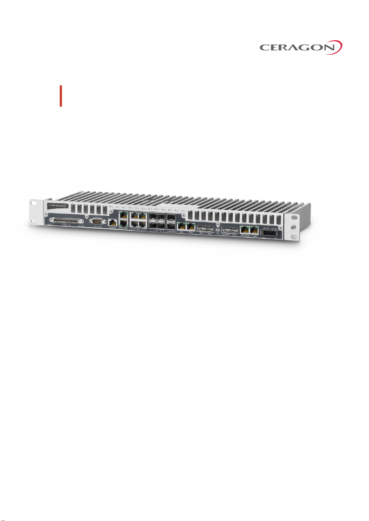
Installation Guide for FibeAir IP-20F
Page 3 of 63
Ceragon Proprietary and Confidential
Table of Contents
1. FibeAir IP-20F Hardware Overview .......................................................................... 11
1.1 Ethernet Traffic Interfaces .........................................................................................................12
1.2 Ethernet Management Interfaces..............................................................................................13
1.2.1 Management Interface Cable Options.......................................................................................13
1.3 E1/DS1 Interface ........................................................................................................................14
1.4 STM-1/OC-3 Interfaces ..............................................................................................................15
1.5 Radio Interfaces .........................................................................................................................16
1.6 Power Interfaces........................................................................................................................17
1.7 Synchronization Interface..........................................................................................................18
1.8 Terminal Interface......................................................................................................................19
1.9 External Alarms..........................................................................................................................20
1.10 Storage Memory Card................................................................................................................21
2. Preparing for Installation......................................................................................... 22
2.1 Transportation/Storage .............................................................................................................23
2.2 Inspection ..................................................................................................................................24
2.3 Unpacking Equipment at the Site ..............................................................................................25
3. Installing the IP-20F IDU.......................................................................................... 26
3.1 Kits required to perform the installation ...................................................................................27
3.2 Tools...........................................................................................................................................28
3.3 Installing the IP-20F IDU in the Rack (19").................................................................................29
3.4 Grounding the IP-20F.................................................................................................................30
3.5 Replacing an IP-20F IDU or SM-Card..........................................................................................31
4. Connecting the Power Cable.................................................................................... 33
4.1 Power Supply Notes...................................................................................................................36
5. Power Supply Notes................................................................................................ 37
6. IDU-RFU Cable Connection ...................................................................................... 38
7. Performing Initial Configuration .............................................................................. 39
7.1 Establishing a Connection..........................................................................................................40
7.1.1 Connecting to the Unit with a Serial Connection.......................................................................40
7.1.2 Connecting to the Unit with a LAN Connection .........................................................................40
7.2 Logging On .................................................................................................................................42
7.3 Changing Your Password............................................................................................................43
7.4 Configuration .............................................................................................................................44