Veris Industries GWNP Series User manual

Z207135-0C Page 1 of 10 ©2016 Veris Industries USA 800.354.8556 or +1.503.598.4564 / suppor[email protected] 0916
Alta Labs, Enercept, Enspector, Hawkeye, Trustat, Aerospond, Veris, and the Veris ‘V’ logo are trademarks or registered trademarks of Veris Industries, L.L.C. in the USA and/or other countries.
Other companies’ trademarks are hereby acknowledged to belong to their respective owners.
TM
Installation Guide
Air Quality
Product Overview
The GWNP Series wall mounted gas platform converts gas sensor readings into a signal that is compatible with
building control sensors. To operate, the GWNP must be used with a Veris AG Series gas sensor (sold separately).
The GWNP board has a connector for mounting a single AG sensor, and this sensor can be replaced at any time
without removing the GWNP from its installed location. Simply remove the GWNP cover, replace the AG sensor
inside, and reinstall the cover (see the installation guide for the AG sensor for more information). To maintain
accuracy, keep all vents free of dust and debris. The GWNP is warranted for a period of ve years.
GWNP Series
BACnet and Modbus Protocol Communication
Wall Mounted Platform for Gas Sensors
Specications
Input Power 15 to 30 Vdc/24 Vac ±20%, Class 2, 50/60Hz, max. 60 mA
Relay Contact Ratings 1 A/30 Vdc, Normally Open
Operating Temperature Range -20 to 50 °C (-4 to 122 °F)
Operating Humidity Range 0 to 90% RH non-condensing
Terminal Block Wire Size 30 to 12 AWG (0.05 to 3.31 mm2)
Terminal Block Torque 0.37 to 0.44 ft-lb (0.5 to 0.6 N-m)
Protection Class (self-evaluated) IP20
Agency Approvals Intertek ETL Listed to UL 61010-1
Note: The GWNP operates only when an AG Series gas sensor is installed (sold separately). Accuracy, sensitivity, setpoints, and measurement
range are dependant on the AG Series sensor connected to the GWNP platform. See the AGxx sensor installation guide for details.
Product Identication
GWN
P = Protocol: BACnet and Modbus
Output
X X
Dimensions
0.6”
(15 mm)
4.5”
(113 mm)
2.75”
(70 mm)
1.2”
(30 mm)
1.1”
(27 mm)
1.7”
(42 mm)
3.25”
(83 mm)
Example:
GWNPXXW
*
*The CE mark indicates RoHS2 compliance. Please refer to the CE Declaration of
Conformity for additional details.
Blank = Black
W = White
Housing
Color

Z207135-0C Page 2 of 10 ©2016 Veris Industries USA 800.354.8556 or +1.503.598.4564 / suppor[email protected] 0916
Alta Labs, Enercept, Enspector, Hawkeye, Trustat, Aerospond, Veris, and the Veris ‘V’ logo are trademarks or registered trademarks of Veris Industries, L.L.C. in the USA and/or other countries.
Other companies’ trademarks are hereby acknowledged to belong to their respective owners.
TM
GWNP Series Installation Guide
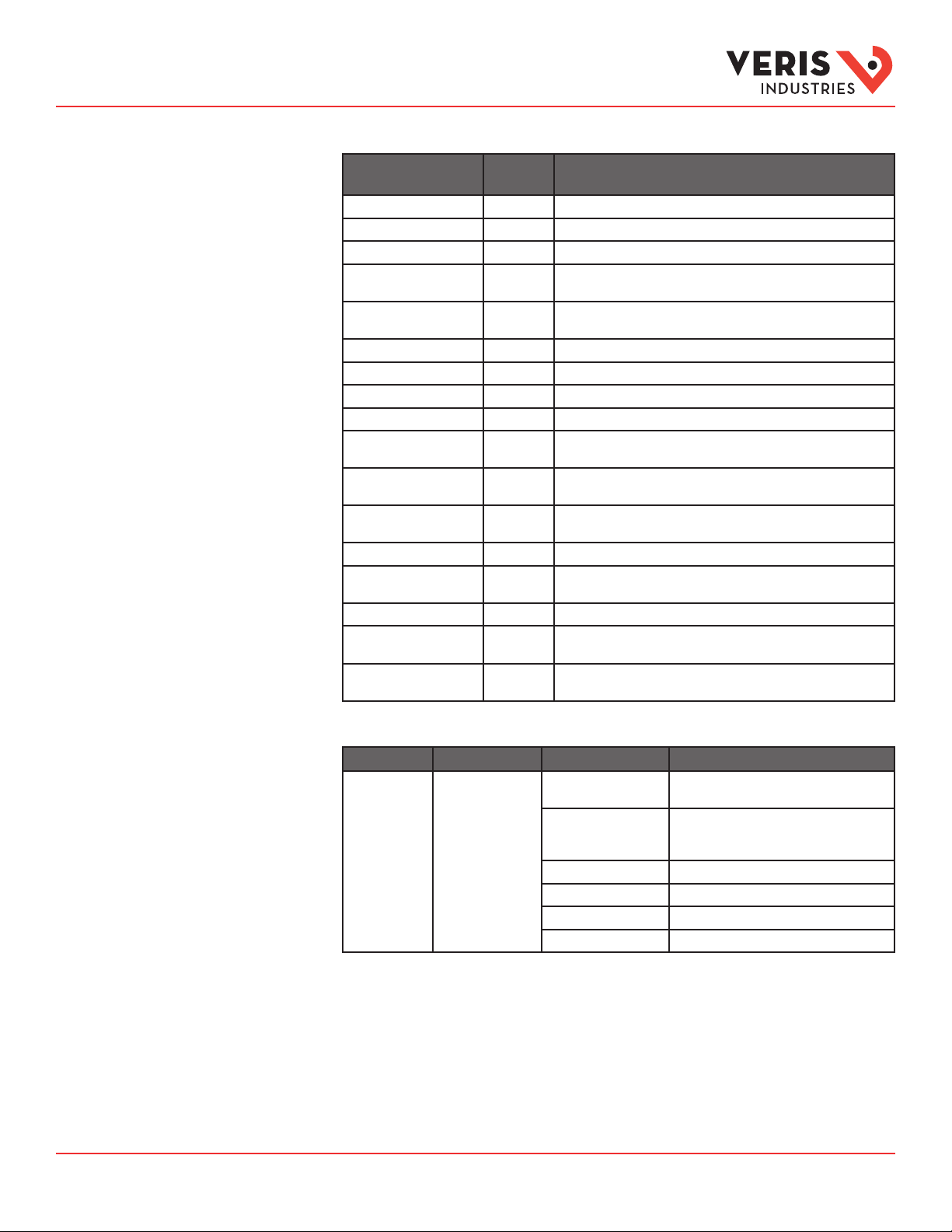
Regulatory Information
• The product is a Class 2 (low voltage - limited energy) device.
• The product is not intended for life or safety applications.
• Do not install the product in hazardous or classified locations.
• Read and understand the instructions before installing the
product. Follow the instructions during installation.
• Turn off all power supplying equipment before working on it.
• Do NOT depend on the product for voltage indication.
• Products rated only for basic insulation must be installed on
insulated conductors.
• The installer is responsible for conformance to all applicable codes
and regulations.
NOTICE
If this product is used in a manner not specified by the manufacturer,
the protection provided by the product may be impaired.
No responsibility is assumed by the manufacturer for any consequences
arising out of the use of this material.
LOSS OF CONTROL
•Assure that the system will reach a safe state during and after a
control path failure.
•Separate or redundant control paths must be provided for critical
control functions.
•Test the eect of transmission delays or failures of communication
links.1
•Each implementation of equipment using communication links
must be individually and thoroughly tested for proper operation
before placing it in service.
Failure to follow these instructions may cause
injury, death or equipment damage.
Control system design must consider the potential failure modes of
control paths and, for certain critical control functions, provide a
means to acheive a safe state during and after a path failure.
Examples of critical control functions are emergency stop and
over-travel stop.
1For additional information about anticipated transmission delays or
failures of the link, refer to NEMA ICS 1.1 (latest edition). Safety
Guidelines for the Application, Installation, and Maintenance of
Solid-State Controls or its equivalent in your specic country,
language, and/or location.
WARNING
For use in a Pollution Degree 2 or better environment only. A Pollution
Degree 2 environment must control conductive pollution and the
possibility of condensation or high humidity. Consider the enclosure,
the correct use of ventilation, thermal properties of the equipment,
and the relationship with the environment.

Z207135-0C Page 3 of 10 ©2016 Veris Industries USA 800.354.8556 or +1.503.598.4564 / suppor[email protected] 0916
Alta Labs, Enercept, Enspector, Hawkeye, Trustat, Aerospond, Veris, and the Veris ‘V’ logo are trademarks or registered trademarks of Veris Industries, L.L.C. in the USA and/or other countries.
Other companies’ trademarks are hereby acknowledged to belong to their respective owners.
TM
GWNP Series Installation Guide
Product Diagram
Pin Connector for AGxx Gas Sensor
An AGxx sensor is required for GWNP
operation. Sensors are sold separately.
Status LED Indicators
Left - red
Center - yellow
Right - green
RX and TX LED Indicators
RX - receiving data
TX - sending data
Settings LED Indicator
OFF during normal conditions
ON when settings have been overridden
by communications
COMM
OVRD
Address
DIP Switch
Configuration
DIP Switch
The LED indicators allow determination of device status at a glance. The GWNP includes a light blocking insert that can be set in
place of the light pipes if this visibility is not desired.
Status LED Blink Codes
Relay Contacts
LED Description
Red • OFF during normal conditions.
• ON solid when the high setpoint is reached.
• Flashes once when the device is initially powered.
• Flashes while the platform is auto-resetting, such as when a sensor is installed.
• Flashes continuously when the sensor reading is over range.
Yellow • OFF during normal conditions.
• ON solid when the low setpoint is reached.
• Flashes once when the device is initially powered.
• Flashes while the platform is auto-resetting, such as when a sensor is installed.
• 1 ash every 10 seconds if possible sensor damage is detected.
• 2 ashes every 10 seconds if the sensor requires replacement.
• 4 or more ashes every 10 seconds if internal problems are detected, such as if the unit needs servicing or if the operating
temperature is out of range.
Green • ON solid during normal operation.
• Flashes once when the device is initially powered.
• Flashes while the platform is auto-resetting, such as when a sensor is installed.
Unit Condition Low Setpoint Relay High Setpoint Relay
OFF Closed Open
ON (everything OK) Open Open
ON (inoperative) Closed Closed
ON (low setpoint reached) Closed Open
ON (high setpoint reached) Closed Closed

Z207135-0C Page 4 of 10 ©2016 Veris Industries USA 800.354.8556 or +1.503.598.4564 / suppor[email protected] 0916
Alta Labs, Enercept, Enspector, Hawkeye, Trustat, Aerospond, Veris, and the Veris ‘V’ logo are trademarks or registered trademarks of Veris Industries, L.L.C. in the USA and/or other countries.
Other companies’ trademarks are hereby acknowledged to belong to their respective owners.
TM
GWNP Series Installation Guide
Installation
Observe precautions for handling static sensitive
devices to avoid damage to the circuitry that
is not covered under the factory warranty.
1. Disconnect and lock out all power supplies before beginning the installation.
2. Choose a location on a wall in the area to be monitored. Install the unit on a standard electrical box centrally, near main trac
paths but away from outside air vents and excessive drafts.
3. Remove the front cover of the GWNP unit, and set it aside.
4. Wiring terminals are located on the back of the unit. Determine whether these terminals t into the electrical box chosen for
the installation. In the case of some electrical boxes, such as weatherproof style boxes, the GWNP may not make a snug t
against the box. If this happens, use the Veris AA66 Foam Gasket Kit accessory to improve the t (sold separately).
5. Run wires through the back of the electrical box and wire the GWNP as shown. Properly shielded wire must be used for all
connections. For the RS-485, use shielded, twisted-pair wire. Connect the shield at one end only. The GND terminal can be
used.
Relay
Power Supply
+
–
Common
High Threshold (HT)
Low Threshold (LT)
RS485(-)
RS485(+)
GND
Power
Modbus
BACnet
6. Mount the GWNP on the box. Use the two mounting holes on the unit and the included #6 screws. The wiring terminals must
face into the electrical box, with the board facing outward.
7. Install the AGxx Series gas sensor according to the directions included with the sensor.
8. Adjust the DIP switches as needed.
9. If desired, replace the LED light pipes with the black plastic light blocking insert (included with the GWNP). The light pipes are
located inside of the front cover.
10. Replace the front cover. Reconnect power.

Z207135-0C Page 5 of 10 ©2016 Veris Industries USA 800.354.8556 or +1.503.598.4564 / suppor[email protected] 0916
Alta Labs, Enercept, Enspector, Hawkeye, Trustat, Aerospond, Veris, and the Veris ‘V’ logo are trademarks or registered trademarks of Veris Industries, L.L.C. in the USA and/or other countries.
Other companies’ trademarks are hereby acknowledged to belong to their respective owners.
TM
Installation Guide
Air Quality
The GWNP includes two sets of DIP switches, as shown in the Product Diagram section. The DIP switch labeled
“ADDRESS” is for addressing. The DIP switch labeled “CONFIG” is for communications conguration.
Address Configuration
Each device on a single network must have a unique address. Set the DIP switch labeled “ADDRESS” to assign a
unique address before the device is connected to the network. If an address is selected that conicts with another
device, neither device will be able to communicate.
Address the GWNP as any whole number between and including 1 to 127. Note that zero is not a valid address
for Modbus; zero is a valid address for BACnet. Positions 1 through 7 of the “ADDRESS” DIP switch designate the
address. Position 8 toggles between the Modbus and BACnet communication protocols, as shown in the diagram
below.
LS
BMSB
124816 32 64
Decimal Values
Binary Address
Modbus/BACnet
Toggle
On = Modbus
Off = BACnet
To set an address using the DIP switch, simply add the values of any switches that are in the ON position.
For example, an address of 73 is set as shown in the diagram below.
73
=
LS
BM
SB
124816 32 64
Position number 1 has an ON value of 1, position number 4 has an ON value of 8 and position number 7 has an ON
value of 64 (1 + 8 + 64 = 73).
Communications Configuration
See the Product Diagram section for the location of the DIP switch labeled “CONFIG”. The following parameters are
congurable:
• Parity (Modbus only): None, Odd, None1 (one stop bit), Even
• Baud rate: 8600, 19200, 38400, 57600 (Modbus), 76800 (BACnet)
• Autobaud: On, O
Note: Autobaud may not be able to automatically determine the baud rate in some situations. In this case, set
Autobaud to OFF and use the manual baud setting.
off off
on off
off on
on on
None
Odd
None1
Even
9600
19200
38400
57600 (Modbus)
76800 (BACnet)
off off
on off
off on
on on
Parity
(Modbus Only)Baud
Autobaud
Yes
No
On
Off
Conguration

Z207135-0C Page 6 of 10 ©2016 Veris Industries USA 800.354.8556 or +1.503.598.4564 / suppor[email protected] 0916
Alta Labs, Enercept, Enspector, Hawkeye, Trustat, Aerospond, Veris, and the Veris ‘V’ logo are trademarks or registered trademarks of Veris Industries, L.L.C. in the USA and/or other countries.
Other companies’ trademarks are hereby acknowledged to belong to their respective owners.
TM
Installation Guide
Air Quality
Example: No Parity, 19200 Baud, Autobaud O
12345
o o on o o
None 19200 Baud Autobaud O
Function Codes
Function Code Function
03 Read holding registers
06 Write single register
08 Diagnostics (Sub-function 00 – Return query data)
16 Write multiple registers
17 Report slave ID – Returns manufacturer, model name, and serial number (standardVeris format)
All of these values correspond to BACnet objects with the same name. See the BACnet Conformance Statement for
their denitions.
Note that an attempt to write to “read only” holding registers will give an error and the entire write command will
not be executed even if writing to read/write locations were also requested. Exception code 2 is given in this case.
“Preserved” means the values is maintained through power outages.
Holding Registers
Register Description
1 Sensor measurement (read only)
2 Sensor scale factor (n in 10n, value would be -2 for percent, -6 for ppm) (read only)
3,4 Sensor measurement in IEEE 32-bit oating point. Most signicant word rst. (read only)
5 Alarm bit map (read only)
Bit 0 (lsb) – High set-point exceeded
Bit 1 – Low set-point exceeded
Bits 2-15 – Zero
6 Alarm bit map override
Bit 0 – High set-point override
Bit 1 – Low set-point override
Bit 2 – High set-point level (1 – Above, 0 – Below)
Bit 3 – Low set-point level
Bits 4-15 – Zero
7 Time to sensor replacement (days remaining) (read only)
8 Run time (days) (read only)
9 Status (read only)
Bit 0 – Over range
Bit 1 – Warmup
Bit 2 – Damage detected
Bits 3-15 – Zero
10-17 Sensor gas type (read only). For example, CO.
All strings packed two characters, big endian, per word. Short strings null terminated.
18-25 Sensor serial number (read only) (always eight hexadecimal digits)
26-41 Manufacturer (read only)“Veris Industries”
42-57 Model (read only)“GWNPxx”
Conguration (cont.)
Modbus Point Map

Z207135-0C Page 7 of 10 ©2016 Veris Industries USA 800.354.8556 or +1.503.598.4564 / suppor[email protected] 0916
Alta Labs, Enercept, Enspector, Hawkeye, Trustat, Aerospond, Veris, and the Veris ‘V’ logo are trademarks or registered trademarks of Veris Industries, L.L.C. in the USA and/or other countries.
Other companies’ trademarks are hereby acknowledged to belong to their respective owners.
TM
Installation Guide
Air Quality
Modbus Point Map (cont.) Register Description
58-73 Location (read/write) preserved. Must be null terminated, 31 characters max.
74 High set-point (read/write preserved). Scaled by value in register 2.Valid values to set are 2 to top of
range. A value of zero resets to sensor default.
75 High hysteresis (read/write preserved). Scaled by value in register 2. Valid values to set are 1 to high set-
point - 1. A value of zero resets to sensor default.
76 Low set-point (read/write preserved). Scaled by value in register 2. Valid values set are 2 to top of range. A
value of zero resets to sensor default.
77 Low hysteresis (read/write preserved). Scaled by value in register 2.Valid values to set are 1 to low set-
point - 1. A value of zero resets to sensor default.
78 DIP switch values. Changing to a non-zero value will cause the current DIP switch settings to be locked in
place. Changing to zero restores dip switch functionality.
79-125 Reserved (read only) returns 0x8000
Note: In the tables below, all properties are read-only unless otherwise noted. “Preserved” means the value is
maintained through power outages.
Present_Value Range Restrictions
Object Name Minimum Value Maximum Value
Device_Instance 0 4,194,302
Identier_Value_Prex 0 4194
High_Set-point
Low_Set-point
2 Maximum range of installed sensor.
High_Hysteresis
Low_Hysteresis
1 High_Set-point-1
Low_Set-point-1
Standard Object Types Supported
Object Type Supported Optional Properties Writable Properties
Analog Input – AI Description
Reliability
None
Analog Value – AV Description Present_Value
Binary Input (supports change of value) Description
Reliability
None
BinaryValue – BV Description Present_Value
Device – DEV Description
Location
Max_Master
Max_Info_Frames
Active_COV_Subscriptions
APDU_Timeout
Description
Location,
Max_Master
Object_Identier
Object_Name
Note: Reliability is “No Sensor” if no sensor is installed.
BACnet Descriptions

Z207135-0C Page 8 of 10 ©2016 Veris Industries USA 800.354.8556 or +1.503.598.4564 / suppor[email protected] 0916
Alta Labs, Enercept, Enspector, Hawkeye, Trustat, Aerospond, Veris, and the Veris ‘V’ logo are trademarks or registered trademarks of Veris Industries, L.L.C. in the USA and/or other countries.
Other companies’ trademarks are hereby acknowledged to belong to their respective owners.
TM
Installation Guide
Air Quality
Objects Table
Object Name Type and
Instance
Description of
Present_Value Property
SENSOR AI 1 Gas concentration of sensor.
LIFETIME AI 2 Remaining hours until sensor replacement.
RUNTIME AI 3 Hours of runtime for sensor.
Device_Instance AV 1 Alternative way to change object_identier property of device. Fractional
values are truncated.
Identier_Value_Prex AV 2 Initially 133, this is the value is prepended to the MAC address in the device
object identier value.
High_Set-point AV 3 High set-point value. Originally sensor high set-point.
High_Hysteresis AV 4 High hysteresis value. Originally sensor high set-point hysteresis.
Low_Set-point AV 5 Low set-point value. Originally sensor low set-point.
Low_Hysteresis AV 6 Low hysteresis value. Originally sensor low set-point hysteresis.
High_Set_point_Exceeded BI 1 Becomes ACTIVE when AI 1 ≥ AV 3; becomes INACTIVE when
AI 1 ≤ (AV 3 - AV 4).
Low_Set_point_Exceeded BI 2 Becomes ACTIVE when AI 1 ≥ AV 5; becomes INACTIVE when
AI 1 ≤ (AV 5 - AV 6).
Device_Object_Reset BV 1 Always reads INACTIVE. Write ACTIVE to reset the Device Objects Object_
Name and Object_Identier to their defaults.
High_Relay_Override BV 2 ACTIVE means BV 3 controls relay, otherwise BI 1 controls the relay.
High_Relay_Level BV 3 When BV 2 is ACTIVE, an ACTIVE BV 3 behaves like the set-point has been
exceeded.
Low_Relay_Override BV 4 ACTIVE means BV 5 controls relay, otherwise BI 2 controls the relay.
Low_Relay_Level BV 5 When BV 4 is ACTIVE, an ACTIVE BV 5 behaves like the set-point has been
exceeded.
Lock_Settings BV 6 When BV 6 is ACTIVE, DIP switches are disabled, and register values control
the settings. When BV 6 is INACTIVE, the DIP switches control.
Device Objects Table
Object Name Object Identifier Object Property Description
GWNxxxx Device 133nnn Object_Identier (R/W) Unique value where nnn initially is MS/TP
address. GWN is the product name.
Object_Name (R/W) Unique name, initially a combination of model
and serial number. Maximum length is 64
characters.
APDU_Timeout Default is 3000, maximum value is 60000.
Max_Master Default is 127
Description Maximum length is 64 characters
Location Maximum length is 31 characters
BACnet Descriptions (cont.)

Z207135-0C Page 9 of 10 ©2016 Veris Industries USA 800.354.8556 or +1.503.598.4564 / suppor[email protected] 0916
Alta Labs, Enercept, Enspector, Hawkeye, Trustat, Aerospond, Veris, and the Veris ‘V’ logo are trademarks or registered trademarks of Veris Industries, L.L.C. in the USA and/or other countries.
Other companies’ trademarks are hereby acknowledged to belong to their respective owners.
TM
Installation Guide
Air Quality
Conformance Statement BACnet Protocol Implementation Conformance Statement
Vendor Name: Veris Industries
Product Name: Veris GWNP Gas Platform Base
Product Model Number: GWNPxx
Application Software Version: 1.0
Firmware Revision: 0.8.2
BACnet Protocol Version: 1
BACnet Protocol Revision: 12
Product Description: Environmental Sensor
BACnet Standardized Device Prole (Annex L):
BACnet Application Specic Controller (B-ASC)
List all BACnet Interoperability Building Blocks Supported (Annex K):
DS-RP-B,DS-RPM-B,DS_WP-B, DS-COV-B,DM-DDB-B,DM-DOB-B,DM-DCC-B
Segmentation Capability: Segmentation not supported
Standard Object Types Supported:
No dynamic creation or deletion supported
No proprietary properties or object types
(other information about objects on preceding pages)
Data Link Layer Options: MS/TP master (Clause 9), baud rates: 9600, 19200, 38400, 76800
Device Address Binding: Static device binding is not supported. (No client functionality is included).
Networking Options: None
Character Sets Supported: ANSI X3.4

Table of contents
Popular Media Converter manuals by other brands

iZ Technology
iZ Technology ADA Operator's manual

Transition Networks
Transition Networks CGETF10XX-10X user guide

CYP
CYP AU-D4T Operation manual

Rose electronics
Rose electronics CNV-VGADVISC Installation and operation manual

TDK-Lambda
TDK-Lambda EZA11K Series Quick manual

Transition Networks
Transition Networks E-TBT-FRL-FD-01 installation guide