Verlinde TVI Series User manual

VERLINDE reserve the right to alter or amend the above information without notice
07/2016
ANGLAIS
INSTRUCTION MANUAL
ELECTRIC WINCH TVI SERIE
Product Distributed in Ireland by:
601, Western Industrial Estate,
Dublin 12, Ireland T: + 353 (0)1
4584836 E: [email protected]
www.prolift.ie

2/30
03/2016
To ensure the constant improvement of its products, VERLINDE reserves the right to change the equipment as
described below and, in this case, to supply products which differ from the illustrations in this instruction manual.
All rights reserved
Summary
1 - Contents.................................................................................................................................................. 2
2 - What not to do......................................................................................................................................... 3
3 - Compulsory regulatory inspections by the user...................................................................................... 3
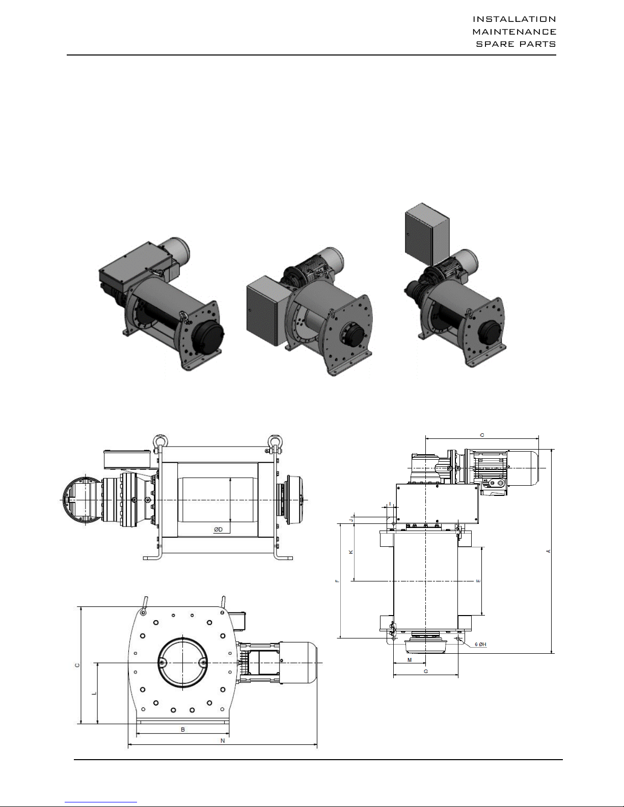
4 - Introduction to the machines................................................................................................................... 4
5 - Handling - Storage.................................................................................................................................. 7
6 - Installation and start-up........................................................................................................................... 7
7 - Servicing and maintenance..................................................................................................................... 14
8 - Decommissioning.................................................................................................................................... 15
9 - Spare parts.............................................................................................................................................. 15
10 - Troubleshooting....................................................................................................................................... 16
11 - Declaration of conformity......................................................................................................................... 17
12 - Appendixes.............................................................................................................................................. 18
1 –Contents
All users are asked to read the start-up instructions carefully before using the winch for the first time. These
instructions will help the user to become familiar with the winch and to use it to the best of its capabilities. The
start-up instructions contain important information on how to use the winch in a safe and correct manner.
Observing these instructions can help prevent risks, minimize repair costs, reduce down time and increase the
reliability and useful life of the winch. The instruction manual must always be available at the winch operation
location. In addition to the start-up instructions and the regulations relating to accident prevention, it is important
to consider current rules in terms of TVIl safety and professional standards in force in each country.
This machine is covered by European regulations and, more specifically, machinery directive
2006/42/CE, EMC directive 2004/108/EC and low-voltage directive 2006/95/EC, as well as standard EN
14492/1.
The TVI Series winches can be used to perform lifting and pulling operations.
When used for lifting, European regulations require the use of certain equipment, including a limit stop and a
load limiter (above 1000 kg).
The user must make sure that this equipment is in place (optionally available from the manufacturer) before
undertaking any lifting operation.
Please ensure that the operator is qualified to operate the winch under the conditions laid down in this
manual. This is to respect the safety of workers and the environment.
The capacity indicated on the winch corresponds to the maximum operational capacity (M.O.C.), which may
not be exceeded in any case.
This winch may not be used to lift personnel under any circumstances.
Do not lift or carry loads while personnel remains in the danger zone.
Do not authorize personnel to walk under a hanging load.
Never leave a load hanging or under tension without supervision.
Never begin to handle a load without fixing it correctly and making sure that all personnel has left the danger
zone.
Before each use, the operator must check that the machine, its ropes, its hook, its markings and its restraints
are in good condition.

3/30
03/2016
The operator must make sure the load is hooked so that the winch, the rope and the load do not pose any
risk for him or other personnel.
The winches can be handled within a range of ambient temperatures between -10° C and +50° C. Please
consult the manufacturer in the case of extreme operating conditions.
Warning: When the ambient temperature is less than 0°C, the brake must be tested in order to make sure it
has no operating faults caused by frost.
All uses of the winches must strictly conform to accident prevention and safety measures for the country
where they are being used.
The manufacturer accepts no responsibility for the consequences of the machines being used or installed in
ways other than described in the manual, or for the consequences of altering or replacing original parts or
components with parts or components from other sources without its written agreement.
YOU ARE ALSO REQUIRED TO OBSERVE THE APPLICABLE RECOMMENDATIONS IN YOUR
COUNTRY.
2 - What not to do
Before using the winch, make sure there is no risk of overloading due to adherence to the floor, suction,
jamming, etc. of the load. In addition to the above, avoid all the incorrect uses and operations indicated
below. It is dangerous and prohibited to:
unwind the drum completely (always leave 2 to 3 coils).
pull at an angle.
swing the load.
use ropes with a diameter and texture that do not comply with the specifications of this manual (FEM 1 Am –
ISO M4)
use damaged or spliced ropes.
use hooks without catches, not suitable for the loads specified on the winch, or in bad condition.
insert objects into the moving parts.
service winches while they are loaded or receiving power.
use the rope of the machine as a sling.
tap on the control box (heating the motor and the electrical controls).
3 –Compulsory regulatory inspections by the user
This equipment has been designed to be subjected to the following tests:
Dynamic proof test at coefficient 1.1
Static proof test at coefficient 1.25
Users are required to conform to the regulations in force in their own countries.
In the case of France:
Order of 1 March 2004 on the testing of lifting machines and accessories:
The amendments to the regulations regarding the use and testing of lifting machines and accessories, in force
since 1 April 2005, impose new obligations on all users:
Adaptation exam, which consists of checking that the lifting machine is suitable for the work the user intends
to carry out as well as for the risks to which the workers are exposed and that the planned operations are
compatible with the conditions for using the machine as defined by the manufacturer.
Assembly and installation exam, which consists of making sure that the lifting machine is assembled and
installed in a safe manner, in accordance with the manufacturer's instruction manual.

4/30
03/2016
Periodic general inspections, including an exam of the state of conservation and operating tests.
Tests for starting or restarting service in the event of changing the operation site, changing the configuration
or the conditions for use on the same site, following dismantlement and reassembly of the lifting machine,
after any considerable replacement, repair or transformation affecting the core components of the lifting
machine, following any accident caused by a failure in a core component of the lifting machine.
The tests must be performed in strict observance of protocol. They aim to provide preventive maintenance,
detecting any damage or faults that can create a risk.
VERLINDE provides an upkeep / maintenance manual for each piece of equipment. It is very important to make
sure that the individuals using the hoist are familiar with the equipment and its correct operation.
VERLINDE agencies are available and may, upon request or by contract, intervene and maintain the winch if
necessary.
If any replacement parts are needed, please specify the following information so that we may supply the
appropriate parts:
- the complete name of the winch
- the complete name of the hoisting motor if necessary
- the serial number of the winch
The 3 items above are listed on the ID plates attached to the winch, motors and on the inspection certificates.
For further information, please contact the winch manufacturer or the distributor.
Manufactured by :
Manufactured by:VERLINDE
VERNOUILLET- FRANCE
2, Boulevard de l'industrie
B.P. 59 28501 VERNOUILLET CEDEX
Phone: +33 (0)2.37.38.95.95
Fax: +33 (0)2.37.38.95.99
4 –Introduction to the machines
4.1 -General
These winches are designed for pulling or lifting loads from 1000 to 10000 kg.
Their FEM classification is 1 Am (ISO: M4)
The TVI Series winches are equipped with the following:
Reduction gear with planetary gears, completely watertight.
Motor 1 speed, three-phase 230/400 V 50 Hz, protection rating IP 55. Operating limits from -10ºC to
+50ºC (without declassification).
24 V very-low voltage control including:
Contactors
Power line isolator
Thermal circuit breaker
Disconnectable button box (2 buttons + emergency stop), 3 m of cable.

5/30
03/2016
Very-low voltage control with variable speed drive (compulsory above 5 tons), comprising:
Power line isolator
Variable-frequency drive
Braking resistance
Button box (2 buttons + emergency stop + potentiometer), not disconnectable, 3 m of cable.
4.2 -Dimensions
Depending on models :
Above the motor (1) on its side (2) or away (3)

6/30
03/2016
a. Low voltage control –Models with 1 speed
b. Low voltage control –Models with frequency inverter
4.3 - Models available
Warning: . the rope diameter shown above corresponds to the recommended rope according to FEM 1 Am /
ISO M4 classification. It also corresponds to the capacity on the last layer.
. it is compulsory to ensure that the resistance coefficient of the rope complies with the lifted load
(FEM 1 Am / ISO M4).
TVI
1 T
2 T
3 T
4 T
5 T
6 T
7 T
8 T
9 T
10 T
05BT/10BT
05BT/09BT
03BT/06BT
02BT/05BT
03BT/07BT
02BT/06BT
02BT/06BT
02BT/05BT
02BT/05BT
03BT/05BT
Position of the electrical unit
(1)
(1)
(1)
(1)
(1) / (2)
(1) / (3)
(1) / (2)
(1) / (2)
(1) / (2)
(1) / (2)
A in mm
911
1050/1045
1065/1090
1169/1194
1194/1220
1224/1250
1241/1267
1241/1267
1288/1087
1314/1288
B in mm
290
420
420
520
520
650
700
700
840
840
C in mm
375
500
500
665
665
765
870
870
975
975
D in mm
125
219,1
219,1
292
292
323,9
355,6
355,6
406,4
406,4
E in mm
350
350
350
350
350
350
350
350
350
350
F in mm
525
590
590
600
600
600
720
720
720
720
G in mm
240
330
330
420
420
420
620
620
750
750
H en mm
12
16
16
22
22
22
30
30
32
32
I in mm
25
45
45
50
50
115
40
40
45
45
J in mm
23
32
32
30
30
30
50
50
47
47
K in mm
263
295
295
300
300
300
360
360
360
360
L in mm
188
262
262
350
350
395
455
455
515
515
M in mm
120
165
165
210
210
210
310
310
375
375
N in mm
716/748
823/902
823/902
905/984
954/1190
1013/1181
1103/1271
1133/1271
1176/1314
1176/1314
0 in mm
548/578
578/657
578/657
578/657
627/795
627/795
662/830
692/830
692/830
692/830
TVI
1 T
2 T
3 T
4 T
5 T
6 T
7 T
8 T
9 T
10 T
05VV/10VV
05VV/09VV
03VV/06VV
02VV/05VV
03VV/07VV
02VV/06VV
02VV/06VV
02VV/05VV
02VV/05VV
03VV/05VV
Position of the
electrical unit
(1)
(1) / (3)
(1) / (3)
(1) / (2)
(2) / (3)
(2)
(2)
(2)
(2)
(2)
A in mm
911
1050/1045
1065/1090
1169/1194
1194/1220
1224/1250
1241/1267
1241/1340
1288/1087
1288/1367
B in mm
290
420
420
520
520
650
700
700
840
840
C in mm
375
579/500
579/500
737/665
665
765
870
870
975
975
D in mm
125
219,1
219,1
292
292
323,9
355,6
355,6
406,4
406,4
E in mm
350
350
350
350
350
350
350
350
350
350
F in mm
525
590
590
600
600
600
720
720
720
720
G in mm
240
330
330
420
420
420
620
620
750
750
H en mm
12
16
16
22
22
22
30
30
32
32
I in mm
25
45
45
50
50
115
40
40
45
45
J in mm
23
32
32
30
30
30
50
50
47
47
K in mm
263
295
295
300
300
300
360
360
360
360
L in mm
188
262
262
350
350
395
455
455
515
515
M in mm
120
165
165
210
210
210
310
310
375
375
N in mm
716/748
823/902
823/902
905/1052
1022/1122
1067/1220
1103/1271
1133/1271
1176/1314
1176/1314
0 in mm
548/578
578/657
578/657
578/657
627/795
627/795
662/830
692/830
692/830
692/830

7/30
03/2016
TVI
Low voltage control –Models with 1 speed
1 T
2 T
3 T
4 T
5 T
05BT
10BT
05BT
09BT
03BT
06BT
02BT
05BT
03BT
07BT
Capacity on the 1rst layer kg
1255
2420
3765
4985
6230
Capacity on the last layer (kg)
1000
2000
3000
4000
5000
Nb of layers
3
3
3
3
3
Wire rope capacity at 1rst layer
m *
17
20
16
16
16
Max. rope capacity (m)
60
71
59
60
60
Rope diameter (mm)
8
11,5
14
18
18
Speed on the 1rst layer m/min
4
8,5
4,5
8
2,5
4,5
2
3,5
2,5
6
Speed on the last layer (m/min)
5
10,5
5,5
9,5
3,5
5,5
2,5
4,5
3
7,5
FEM
1Am
1Am
1Am
1Am
1Am
Motor (kW)
1,1
2,2
2,2
4
2,2
4
2,2
4
3
9,2
Supply
3 Ph - 230/400
V
3 Ph - 230/400 V
3 Ph - 230/400 V
3 Ph - 230/400 V
3 Ph - 230/400 V
Weight (winch without wire
rope) kg
140
150
260
280
260
280
440
470
450
530
TVI
Low voltage control –Models with 1 speed
6 T
7 T
8 T
9 T
10 T
02BT
06BT
02BT
06BT
02BT
05BT
02BT
05BT
03BT
05BT
Capacity on the 1rst layer kg
7480
8725
9975
11120
12355
Capacity on the last layer (kg)
6000
7000
8000
9000
10000
Nb of layers
3
3
3
3
3
Wire rope capacity at 1rst layer m *
16
15
15
16
16
Max. rope capacity (m)
60
60
60
62
62
Rope diameter (mm)
20
22
22
24
24
Speed on the 1rst layer m/min
1,5
5
1,5
4,5
2
4
1,5
4
2
3,5
Speed on the last layer (m/min)
2
6
2
5,5
2,5
5
2
4,5
2,5
4,5
FEM
1Am
1Am
1Am
1Am
1Am
Motor (kW)
3
9,2
3
9,2
4
9,2
4
9,2
5,5
9,2
Supply
3 Ph - 230/400 V
3 Ph - 230/400 V
3 Ph - 230/400 V
3 Ph - 230/400 V
3 Ph - 230/400 V
Weight (winch without wire rope) kg
580
660
840
910
850
910
1160
1230
1180
1230
TVI
Low voltage control –Models with frequency inverter
1 T
2 T
3 T
4 T
5 T
05VV
10VV
05VV
09VV
03VV
06VV
02VV
05VV
03VV
07VV
Capacity on the 1rst layer kg
1255
2420
3765
4985
6230
Capacity on the last layer (kg)
1000
2000
3000
4000
5000
Nb of layers
3
3
3
3
3
Wire rope capacity at 1rst layer
m *
17
20
16
16
16
Max. rope capacity (m)
60
71
59
60
60
Rope diameter (mm)
8
11,5
14
18
18
Speed on the 1rst layer m/min
4
8,5
4,5
8
2,5
4,5
2
3,5
2,5
6
Speed on the last layer (m/min)
5
10,5
5,5
9,5
3,5
5,5
2,5
4,5
3
7,5
FEM
1Am
1Am
1Am
1Am
1Am
Motor (kW)
1,1
2,2
2,2
4
2,2
4
2,2
4
3
9,2
Supply
3 Ph - 230/400
V
3 Ph - 230/400 V
3 Ph - 230/400 V
3 Ph - 230/400 V
3 Ph - 230/400 V
Weight (winch without wire
rope) kg
150
155
270
300
270
300
450
500
480
540

8/30
03/2016
TVI
Low voltage control –Models with frequency inverter
6 T
7 T
8 T
9 T
10 T
02VV
06VV
02VV
06VV
02VV
05VV
02VV
05VV
03VV
05VV
Capacity on the 1rst layer kg
7480
8725
9975
11120
12355
Capacity on the last layer (kg)
6000
7000
8000
9000
10000
Nb of layers
3
3
3
3
3
Wire rope capacity at 1rst layer m *
16
15
15
16
16
Max. rope capacity (m)
60
60
60
62
62
Rope diameter (mm)
20
22
22
24
24
Speed on the 1rst layer m/min
1,5
5
1,5
4,5
2
4
1,5
4
2
3,5
Speed on the last layer (m/min)
2
6
2
5,5
2,5
5
2
4,5
2,5
4,5
FEM
1Am
1Am
1Am
1Am
1Am
Motor (kW)
3
9,2
3
9,2
4
9,2
4
9,2
5,5
9,2
Supply
3 Ph - 230/400 V
3 Ph - 230/400 V
3 Ph - 230/400 V
3 Ph - 230/400 V
3 Ph -
230/400 V
Weight (winch without wire rope) kg
610
670
870
920
880
920
1190
1250
1210
1250
* Rope and hook extra.
The diameter of the wire rope corresponds to the capacity on the last layer
4.4 -Options
The TVI Series winches can be supplied with the following options:
Clock-type limit switch
Easily adjustable, this system guarantees safety by setting top and bottom limits.
IP 65 limit switch
Electronic load limiter
Device with display which stops the winch in the event of an overload without breaking the kinematic chain.
Slotted drum
Enables correct winding of the rope on the first layer.
Secondary brake
Emergency trouble shooting hand wheel
Multi rope grooved drum
Lower chassis
Tarpauline cover
Special paint (C4, C5M)
Rope presser roller
Essential complement for the slotted drum if the rope is not permanently tight.
Manual unblocking of the brake with automatic return
Manual control
Handwheel or crank associated with a brake unblocking system.
Rope-slack switch
Detects rope that is not under tension.
2nd rope attachment
Option for creating a back-and-forth system or for lifting a load at two points.
Timer
Allows the user to add up the total time of winch operation and makes it easier to use the maintenance log.
Phase order detector
Allows the winch not to be connected with raising / lowering inversion.
Hauling radio control
Adjustable speed drive hauling radio control
Lifting radio control
Proportional adjustable speed drive lifting radio control
Any other requirements : consult us.

9/30
03/2016
4.5 - Classification FEM
There are eight groups of mechanisms:
FEM
1 Dm
1 Cm
1 Bm
1 Am
2m
3m
4m
5m
ISO
M 1
M 2
M 3
M 4
M 5
M 6
M 7
M 8
To determine the group of a given lifting device, winch or hoist, three essential parameters must be
considered:
4.5.1. - Maximum load to be lifted
Including the weight of the rope and any lifting accessories used (hook, etc.) unless these have a total
weight equal to or less than 5% of the load to be lifted.
4.5.2. - Strain condition
Specifies the proportions in which the lifting machine is used with maximum load or reduced load. Four
characterized strain conditions are identified in this way:
Light
Lifting machines exceptionally subjected to the maximum
strain and commonly to very light strains.
k ≤ 0.5
Medium
Lifting machines often subjected to the maximum strain
and commonly to light strains.
0.5 < k ≤ 0.63
Heavy
Lifting machines frequently subjected to the maximum
strain and commonly to medium strains.
0.63 < k ≤ 0.8
Very
heavy
Lifting machines regularly subjected to the strains near to
the maximum strain.
0.8 < k ≤ 1
4.5.3. –FEM classification
Strain
condition
Average operating time per day, in hours
30’
1 h
2 h
4 h
8 h
16 h
More than
16 h
Light
1 Dm
1 Cm
1 Bm
1 Am
2m
3m
4m
Medium
1 Cm
1 Bm
1 Am
2m
3m
4m
5m
Heavy
1 Bm
1 Am
2m
3m
4m
5m
Very heavy
1 Am
2m
3m
4m
5m
5 –Handling - Storage
When handling the winch, use slings that are compatible with the slinging points provided for this purpose on
the winch.
Warning: the angle formed between the hook and the two slinging points must be at most 45º.
Lift and set down the winch with care, without letting it fall, bearing in mind the offset centre of gravity.
For further information on the weight of the winch, consult the Technical Specifications chapter.
These winches must be protected from the elements, in a dry and clean location, at temperatures comprised
between -10ºC and +50ºC.

10/30
03/2016
6 –Installation and start-up
6.1 –Fixings
The TVI Series winches must necessarily be installed on a flat, solid and safe surface that can withstand the
loads to which it will be subjected. An unsuitable installation location can result in serious accidents.
To assess the suitability of an installation location and its load resistance, it is advisable to take into account any
possible overloads, the weight of the actual winch as well as the weight of the optional components and/or
accessories installed on it, including any dynamic forces. The winch operator is responsible for selecting the
installation location. In the event of any doubts regarding the suitability of an installation location, consult a civil
engineer or a stress and strain specialist.
Correctly tighten the fixing bolts (see tables 4.2 and 4.3)
Screw/Nut
Tightening torque screw / Nut quality 8.8
Nm
M10
51
M12
85
M14
140
M16
210
M20
410
M24
710
6.2 - Mains power supply
Very important: the winch will only operate with full power when the motor is correctly supplied with a suitable
cable cross-section.
Provide voltage protection before the electric box.
An isolator must be installed at least 10 meters from the usage location.
6.3 - Adjusting the limit switch (optional)
The TVI Series winches are available with two types of limit switches:
Clock type: Remove the protective cover of the device (inside this cover you will find the diagram below). The
levers, which are now accessible, can be turned manually.
Adjustment of the winding stop point:
Wind the rope to the maximum desired winding point. Stop the winch.
Still in this position, manually move the red lever (2) to the lowest position of the rotation circle, where it
activates the switch (3)
Adjustment of the unwinding stop point:
Unwind the rope to the maximum desired unwinding point. Stop the winch.
Still in this position, manually move the black lever (1) to the lowest position of the rotation circle, where it
activates the switch (3)

11/30
03/2016
Type with IP65 cam: Remove the protective cover of the device, the cams (1) which are now accessible can be
positioned with the help of a worm (2) using a screwdriver.
1 2
Each adjustment screw (2) corresponds to a TOP or BOTTOM limit position.
Adjustment of the top winding stop point:
Wind the rope to the maximum desired winding point. Stop the winch.
Still in this position, with the help of a suitable screwdriver, turn the adjustment screw (2) until a click is heard in
the contactor.
Adjustment of the bottom unwinding stop point:
Unwind the rope until the bottom point, always leaving 3 safety turns on the drum. Stop the winch.

12/30
03/2016
Still in this position, with the help of a suitable screwdriver, turn the adjustment screw (2) until a click is heard in
the contactor.
This range of limit switches also includes a model with 4 positions.
If you need more positions, do not hesitate to consult us.
6.4 - Working rope
Warning: the direction of rotation of the drum depends on the connection of the machine.
Reminder: check the maximum capacity of the winch (see Models available § 4.4).
Very important:
Safety regulations require 2 to 3 coils of rope to be left on the drum at all times.
To comply with the legislation, the rope should not exceed the recommended diameter.
Make sure the rope and hook used guarantee a safety level corresponding to the table in §4.4 if they were not
supplied by the manufacturer with the machine.
The useful life of the steel ropes used on the winch depends on many factors, including the conditions of the
work cycles (lifting height, lifting speed, number and type of deviations, etc.) as well as the operating mode
(number of winding layers, working cycle distribution along the length of the steel rope, etc.). The potential
useful life of the steel ropes is therefore subject to considerable variations according to these points.
It is important to remember that any replacement ropes must use materials with the same characteristics as the
original rope.
This replacement must be included in the maintenance log.
Measuring the rope diameter:
Correct measurement Incorrect measurement
with slide caliper
Handling of steel ropes:
Always use suitable protective gloves when handling steel ropes
Never use any ropes that have defects such as:
An unacceptable number of broken strands
Birdcaging
Birdcaging
Flattening
Shrinkage
Strand extrusion
Broken cable cores
Slack strands
Bends or kinks
Always check the rope for wear before using it.
Never use steel ropes as loops
Never expose the steel ropes to jagged lips or sharp edges

13/30
03/2016
Unwinding the rope on its reel:
CORRECT
INCORRECT
Fixing the rope :
The ropes are supplied as standard with a rope attachment suitable for the recommended rope and installed
according to a standard rope outlet.
Align the rope clamp with the hole made in the winch for this purpose.
Pass the rope through the slot of the flange and place it between the flange and the rope clamp, taking care to
position it correctly in the rope clamp slot. Make the rope exceed the limit of the outer diameter of the flange.
Once the 4 screws are correctly tightened, the rope is properly installed.
The rope should not form loops in any case.
Winding the rope on the drum :
Tension the rope and wind it around the drum in close joining coils.
Check the winding direction of the rope according to the motor connection.
Start to wind the rope forming a spiral to the right. In order to facilitate this operation, some drums are provided
with a heel attached to one of the flanges, which "fills" the space between the first turn and the flange.
The first layer must be wound in a compact manner and under tension. Take a mallet or a block of wood and
knock the turns against one another; not too hard to prevent the strands from overlapping one another, but
tightly enough to prevent the rope from moving on the drum. If the first layer is wound too loose, the next layer
will form a space in the first layer that will result in an open area. If the first layer is too tight, the subsequent
layers will not have enough space between turns.
In any case, the first layer and all the other layers must be wound onto the drum with enough pre-tension (5-10
% of the MWL of the rope). If the rope is wound without any tension, it will suffer from crushing and premature
flattening caused by the loaded upper layers.
Even if the first layer is wound correctly during installation, it will expand a little while in service. When the first
layer expands (loss of pre-tension) the initial procedure MUST be performed at regular intervals.
Otherwise, the "hard" turns will severely crush the base layers.
Whatever you do, DO NOT pass the rope through a clamping mechanism. For example, two blocks of wood
screwed together. THIS WILL CAUSE IRREPARABLE DAMAGE TO THE ROPE!

14/30
03/2016
Reeving diagrams :
Bending angle :
Smooth drum: = max. 1.5°
Slotted drum: = max. 2°
D = 20 times L
6.5 - Rope press roller
This option can be used to hold the rope in the slot of the drum.
It has different positions according to the required rope outlet. It is therefore necessary to define the rope outlet
for the control.

15/30
03/2016
6.6 - Rope slack switch
This option can detect a loss of tension in the rope due to, for example, the load being set on the ground.
It has different positions according to the required rope outlet. It is therefore necessary to define the rope outlet
for the control
6.7-Load limiter (optional)
This device stops the winch in the event of an overload without the breakage of the kinematic chain.
Compulsory when lifting loads over 1000 kg (Directive 2006/42/EC) in order to avoid rope breakage,
structure deformation and accidents due to problems caused by overloading.
7 –Servicing and maintenance
Observe the following instructions, in particular if your winch is used in a large number of different locations or in
a particularly dirty or humid environment:
Remove as much dirt as possible from the winch.
Always store the winch in a dry and clean location.
7.1 - Before starting up, check the following
The oil level of the reduction gear
The fixing of the rope on the drum.
The external appearance of the winch.
7.2 -First start-up
At the start of the installation, you are advised to observe a running-in period at ¾ of the load for approximately
thirty hours. The rated force is obtained after this running-in period.
7.3 - Periodic service
Every 100 hours, check the oil level of the reduction gear.
Every 500 hours, drain the reduction gear.
The reduction gear must be lubricated using Esso Glycolub Range 220 mineral oil (or equivalent).
Model
Amount
(liters)
TVI 1T
1,7
TVI 2T –3T
2,3
TVI 4T –5T
3,3
TVI 6T
4
TVI 7T –8T
7
TVI 9T –10T
9
Very important:
If you change the type of oil, please contact our after-sales department.
Bearing lubrication: every 100 hours.

16/30
03/2016
Ropes
The ropes must be cleaned and lubricated regularly using a special lubricant that penetrates to the cable core.
Only use cleaning products that are suitable and harmless for all the components of the rope, including the core.
If greasing cannot be carried out due to operational reasons, its useful life will be noticeably shorter and it will
therefore necessary to increase monitoring of the rope.
The ropes must be checked visually every day.
Hooks
Check the hook and its safety catch.
If the rope and the hook are not supplied by the manufacturer, check that they guarantee a safety level
corresponding to the table in §4.4.
Check the snatch block fastening points on a regular basis.
8 - Decommissioning
Once the equipment has reached an age at which it may pose hazards, the user is obliged to dispose of the
equipment, i.e. taking it out of operation and dismantling it if required.
9 –Spare parts
If during the maintenance operations you detect that certain parts of your winch need to be replaced, only use
original VERLINDE parts.
When ordering spare parts, please provide the following information with your order:
Type and capacity of the winch (on the data plate).
Serial number and year of manufacture (on the data plate)
Number or name of the required parts (exploded views).

17/30
03/2016
10 –Troubleshooting
Fault
Possible cause
Solution
Motor does not start.
Power supply interrupted.
Check and correct the problem.
Check the emergency stop.
The brake does not unblock
See "brake fault"
The contactor does not respond,
Fault in the control.
Check the contactor control and
Get rid of the error.
Limit switch triggered.
Check the limit switch.
Motor does not start
or has difficulty
starting.
The voltage or the frequency are
very different from the set values
when starting the motor.
Improve the mains conditions.
Check the cable cross-sections.
The motor purrs and
consumes
a lot of current.
The brake does not unblock
See "brake fault"
Faulty winding.
Take the motor to an authorized
service center
for repairs.
A power supply phase is missing.
Check the power supply.
Circuit breaker trips
instantly.
Short-circuit in the power cables.
Get rid of the short-circuit.
Short-circuit in the motor.
Have the fault corrected at an
authorized service center,
Power cables not connected
correctly.
Correct the connection.
Motor ground fault.
Have the fault corrected at an
authorized service center,
Speed considerably
reduced under load.
Voltage drop.
Increase the cross-section of the power
cable.
Motor overheating
(temperature
measurement)
Insufficient ventilation.
Free up the ventilation shafts.
Excessively high ambient
temperature.
Observe the authorized temperature
range.
Poor contact of the power cable
(temporary operation with 2
phases)
Get rid of the poor contact.
Circuit breaker tripped.
Poor contact on the relays.
Service factor exceeded (S1 to
S10, DIN 57530), e.g. due to an
excessively high start-up rate.
Adapt the service factor to the
recommended conditions and, if
necessary, call a specialist to
determine the motor.
Excessively noisy
drive
Vibration of the rotating elements.
Check the balance and get rid of the
cause of the vibrations.
Foreign bodies in the ventilation
shafts.
Clean the ventilation shafts.
The brake does not
unblock
Incorrect voltage in the brake
rectifier.
Apply the voltage specified on the data
plate.
Faulty brake control.
Replace the brake control, check the
brake coil (internal resistance and
insulation) and the relays.
Max. air gap exceeded due to
wear of the linings.
Measure and, if necessary, correct the
air gap.
Voltage drop > 10% of input
power.
Guarantee correct power supply, check
the cable cross-section.
Short to frame or between the
turns.
Have the complete brake including
rectifier replaced at an authorized
service center, check the relays.
Faulty rectifier.
Replace the brake coil and rectifier.
The motor does not
brake.
Incorrect air gap.
Measure and, if necessary, correct the
air gap.
Brake linings completely worn.
Replace the entire backplate.

18/30
03/2016
11 –Declaration of EC conformity

19/30
03/2016
12 –Appendixes
A –References of parts
B –Load limiter
C - Limit switch (optional)

20/30
03/2016
A - References of parts
TVI 1T
Table of contents
Other Verlinde Winch manuals
Popular Winch manuals by other brands

Ribimex
Ribimex Ribitech PRTRM540S User and maintenance manual

Comeup
Comeup Seal Gen2 12.5rs Instruction guide

Runva
Runva 20000NH Assembly & operating instructions

pela tools
pela tools PA990 user manual

PREMIER WINCH
PREMIER WINCH DV-6000S manual

Champion Power Equipment
Champion Power Equipment T-P2500 Assembly & operating instructions

STEIN
STEIN RCW-3001 instructions

Toolland
Toolland WKH3000B user manual

WARRIOR
WARRIOR 20SPS12 Assembly & operating instructions

HP Autozubehor
HP Autozubehor 25321 instruction manual

Einhell Global
Einhell Global SHZ 300-2 operating instructions

Gude
Gude 01709 Translation of original operating instructions