Vermason 222660 User manual

Digital Static Fieldmeter
Operation and Maintenance
UNIT C, 4TH DIMENSION, FOURTH AVENUE, LETCHWORTH, HERTS, SG6 2TD UK
Phone: 0044 (0) 1462 672005, Fax: 0044 (0) 1462 670440 • e-mail: Service@Vermason.co.uk, Internet: Vermason.co.uk
TB-7552 December 2008 Page 1 of 3 © 2008 Vermason
Figure 1. 222660 Digital Static
Fieldmeter
Description
The Vermason Digital Static Fieldmeter
is a high quality, portable non-contacting
static fieldmeter which produces
consistently accurate readings with ease
and provides years of trouble-free
operation.
“Periodic audits of facilities …shall be
undertaken by a nominated person or
team using appropriate measuring
equipment where required. A check
shall be carried out on the adequacy
and availability of records. (EN 61340-
5-1 paragraph 10.1 Periodic audits)
“A check shall be carried out to ensure
that discarded packaging and other
materials that may be electrostatic
generative, or not in compliance with the
relevant parameters of clauses 5 and 7,
are disposed of promptly in a way that
does not put ESDS [ESD sensitive
items] at risk.” (EN 61340-5-1
paragraph10.10 Check of discarded
packaging and other materials)
“A check shall be carried out to ensure
that electrostatic fields are not greater
than those specified in 5.3.5.” [10,000
v/M] (EN 61340-5-1 paragraph 10.11
Electrostatic fields)
The Digital Static Fieldmeter indicates
surface voltage and polarity on objects
up to ±19.99 kV at a distance of 1 inch
with an accuracy of ±5% of the
displayed value. It is chopper-stabilized
for use under almost any conditions
including ionised environments. The
conductive case and ground snap
facilitate grounding for accurate
measurement. Also featured are a zero
knob and a push-button hold function. A
unique LED rangefinder system provides
accurate positioning of the meter from
the target.
Its accuracy is dependent upon three
factors:
• Grounding of the meter via a ground
cord or a grounded operator.
• The instrument must be properly
zeroed.
• The distance from the front edge of
the case to the target or surface
under examination must be
accurately defined.
Packaging
1 Digital Static Fieldmeter
1 9V Alkaline Battery
1 Cord with 2.5mm Mono Plug
1 Certificate of Calibration
Operation
Controls
The Digital Static Fieldmeter has two
switches, one for ON/OFF and one for
HOLD/MEASURE plus ZERO adjust
knob. The push button is two-position.
Pressing the button puts it into the lower
(MEASURE) position. Releasing the
button places it in its upper (HOLD)
position. The ZERO knob is turned to
the left or right to change the zero
setting of the display.
Turning the Meter ON and OFF
Slide the switch to the ON position. The
meter will turn on. To turn the meter
OFF, slide the switch to the OFF
position. The meter will now be off.
Battery Check
After turning on power to the meter,
check the display and make sure that
the low battery symbol is NOT lit. If the
battery symbol appears, replace the
battery (see page 2).
Zero the Meter
Turn on the meter with the ON/OFF
slide switch. Press the push button
down so that it is in the lower or
MEASURE position. Place the meter 1
inch from a GROUNDED metal surface.
The red bullseye (ranging lights) should
be in focus on the surface and the meter
should read “0.00”. If the display does
not read “0.00”, adjust the ZERO knob
until the display reads “0.00”.
Making a Measurement
Place the meter 1 inch from the object to
be measured. This distance is
measured from the front edge of the
meter case to the surface of the object.
The meter now displays a reading (from
0 to ±19.99) of the electrostatic field in
kilovolts per inch.
NOTE: In the MEASURE position, the
RANGING LIGHTS are on. These lights
are provided to help place the meter at
the correct distance from the object.
The lights are set to produce a
concentric RED BULLSEYE pattern on a
flat opaque surface 1 inch form the front
edge of the meter. This can be
practiced by aiming the meter at a sheet
of white paper.
If the numeral “1” appears on the left
side of the display, the meter’s range of
20 kV per inch has been exceded.
When this occurs, move the meter
farther away from the object and multiply
the reading by the distance (in inches)
away from the object being measured
(as shown in the figure). The
measurement accuracy is dependent on
a stable ground reference and the 1 inch
measuring distance. It is also
dependent on the “aspect ratio”, relating
the size of the object to be measured to
the measurement distance.
TECHNICAL BULLETIN TB-7552
Made in America

NOTE: This aspect ratio should be at
least 3 for best accuracy, i.e. the object
should be at least a 3” square when
measuring at a 1” distance. Accurate
measurements may be made at other
measurement distances by scaling the
meter range and observing the proper
aspect ratio. For example, at a
measurement distance of 3”, multiply the
meter reading by 3 to give a range of 0
to 60 kilovolts. For accuracy, the object
being measured at this distance should
be at least a 9” square.
Holding Last Reading
With the meater positioned 1 inch from
the object being measured, press the
MEASURE/HOLD pushbutton so that it
releases to the upper or HOLD position.
This will freeze the reading from the
object on the display and allows the
operator to move the meter where it may
be more easily read, or saved for later
reference. In the HOLD position the red
LED will illuminate. The analog output
signal is also held.
NOTE: In the HOLD position, the
bullseye (ranging lights) will be off.
When the push button is returned to the
MEASURE position, the bullseye will
light.
Analog Output
The “RECORD” output jack located on
the face of the unit accepts a standard
2.5mm monaural phone plug and is
provided so the output of the Digital
Static Fieldmeter may be connected to
an oscilloscope, strip chart recorder,
external meter or other device. Use the
included cord to achieve a connection
between the fieldmeter and alternate
measuring instrument. ±10 mV at this
jack corresponds to ± 1 kV.
Battery Replacement
The Digital Static Fieldmeter operates
from a standard 9 VDC alkaline battery.
Battery life is in excess of 30 hours
under normal use. When the battery
voltage drops below 6.7 volts, a battery
symbol will appear in the display. To
change the battery, slide the battery
cover down at the back of the meter and
remove the battery from the battery clip.
Replace the battery with a fresh one and
reinstall the battery cover. The battery
should be removed from the meter if its
is to be stored for an extended period of
time.
Maintenance
The Digital Static Fieldmeter is factory
calibrated and no maintenance is
required. If for any reason you believe
the meter is not working correctly,
contact Vermason Customer Service at
0044 (0) 1462 672005. CAUTION -
There are no user serviceable parts.
Any unauthorized service will void the
warranty and result in additional repair
charges.
Specifications
Display:
3.5 digits, 9.5mm digit height LCD
Response:
<1 sec., 10% to 90% equivalent
to 5Hz output
Range:
±0.00 to ±19.99 kV/inch (25mm)
Accuracy:
±5% of displayed value
Environment:
0 - 50°C at 85% RH
(non-condensing)
Analog Output:
2.5mm phone jack/plug
±10 mV corresponds to ±1 kV
Power:
9 VDC alkaline battery
Battery life in excess of 30 hours
Size:
6.1cm x 10.6cm x 3.3cm
Weight:
141g (with battery)
UNIT C, 4TH DIMENSION, FOURTH AVENUE, LETCHWORTH, HERTS, SG6 2TD UK
Phone: 0044 (0) 1462 672005, Fax: 0044 (0) 1462 670440 • e-mail: Service@Vermason.co.uk, Internet: Vermason.co.uk
TB-7552 Page 2 of 3 © 2008 Vermason
Thousands
Hundreds
Tens
Figure 2. Reading the Digital Static
Fieldmeter
Digital Static Fieldmeter
Accessories
Vermason offers accessories for the
Digital Static Fieldmeter designed to
facilitate routine auditing and periodic
testing of ionization equipment. The
meter and accessories combination can
be used to audit an ionizer's overall
performance. This highly portable test kit
allows the user to make quick and
accurate balance level and neutralization
efficiency measurements. These
accessories are available as the 222661
Charging Plate and 222662 Personal
HBM Test Fixture.
Figure 4. Auditing ionization equipment
with the Digital Static Fieldmeter and
Charging Plate
30cm
30cm
Figure 3. Installing the 222661 Charging
Plate
Personal HBM Test Fixture
(Requires the 222661 Charging Plate
to be installed first)
The Vermason 222662 Personal HBM
Test Fixture turns your model 222660
Digital Field Meter into a Human Body
Model tribo-electric charging tester. This
kit will allow you to measure electrical
charges generated on the human body
while walking or moving across an
insulative or conductive surface. It has
been specially designed to measure

Limited Warranty
Vermason expressly warrants that for a
period of one (1) year from the date of
purchase, Vermason Digital Static
Fieldmeters will be free of defects in
material (parts) and workmanship
(labour). Within the warranty period, a unit
will be tested, repaired or replaced at
Vermason’s option, free of charge. Call
Customer Service at
0044 (0) 1462
672005
for a Return Material
Authorisation (RMA) and for proper
shipping instructions and address. Any
unit under warranty should be shipped
prepaid to the Vermason factory. You
should include a copy of your original
packing slip, invoice, or other proof of
purchase date. Warranty repairs will take
approximately two weeks.
If your unit is out of warranty, Vermason
will quote repair charges necessary to
bring your unit to factory standards. Call
Customer Service at
0044 (0) 1462
672005
for a Return Material
Authorisation (RMA) and proper shipping
instructions and address.
Warranty Exclusions
THE FOREGOING EXPRESS
WARRANTY IS MADE IN LIEU OF ALL
OTHER PRODUCT WARRANTIES,
EXPRESSED AND IMPLIED, INCLUDING
MERCHANTABILITY AND FITNESS FOR
A PARTICULAR PURPOSE WHICH ARE
SPECIFICALLY DISCLAIMED. The
express warranty will not apply to defects
or damage due to accidents, neglect,
misuse, alterations, operator error, or
failure to properly maintain, clean or repair
products.
Limit of Liability
In no event will Vermason or any seller be
responsible or liable for any injury, loss or
damage, direct or consequential, arising
out of the use of or the inability to use the
product. Before using, users shall
determine the suitability of the product for
their intended use, and users assume all
risk and liability whatsoever in connection
therewith.
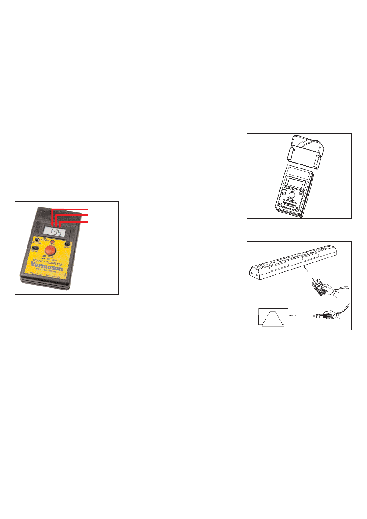
Figure 6. Using the Personal HBM Test
Fixture to measure charges on the body
UNIT C, 4TH DIMENSION, FOURTH AVENUE, LETCHWORTH, HERTS, SG6 2TD UK
Phone: 0044 (0) 1462 672005, Fax: 0044 (0) 1462 670440 • e-mail: Service@Vermason.co.uk, Internet: Vermason.co.uk
TB-7552 Page 3 of 3 © 2008 Vermason
static charges produced by walking
across substrates such as carpeting,
vinyl floor tile, and sealed concrete. It
can also be used to detect charge
generation on surfaces such as
conductive or dissipative floor tiles and
carpeting. An ESD technician may also
use this tool to verify proper grounding
between a conductive or dissipative floor
surface and a person wearing personal
grounding devices such as foot
grounders. The amount (or size) of the
charge generated will vary from one
human body to another. Other factors
such as humidity, contamination
between the foot and flooring surface, as
well as human body capacitance will
also affect the amount of charge
generated.
Installation and Removal
If the fixture needs to be removed to
allow use of the Field Meter alone, see
Figure 5.
To obtain the desired result, a ground
cord must be installed onto the Field
Meter and attached to a utility or
common ground point.
Method of Operation
In order to obtain the desired test
results, the meter must be properly
grounded as stated in the Installation
and Removal section. Once installed on
the Fieldmeter, the Test Fixture itself is
isolated from the meter case and ground
and should remain that way.
Cradle the Test Fixture in the palm of
your hand. Once the meter is grounded
and you are standing on the substrate to
be tested, simply walk around, shuffle
your feet or raise a foot, to determine if
the combination of footwear and
substrate produces an electrical charge.
If an electrical charge is generated and
induced onto the human body, the Test
Fixture will transfer that charge onto the
Fieldmeter, and the amount of the
charge will be registered. If it is
necessary to record the amount of
charge, you can save the result by
simply pressing the Hold button on the
front of the Fieldmeter, and pressing the
button with an insulated object. This test
can be done regardless of the type of
footwear or substrate combination.
Other items in your ESD Control
Program may also be tested such as
conductive or dissipative chairs. Simply
sit in the chair on the desired substrate
and move the chair back and forth to
determine if the chair and human body
combination produces and electrical
charge.
Figure 5. Installing the 222662 Personal
HBM Test Fixture on the Digital Static
Fieldmeter with Charging Plate
A: Slide the Digital Static Fieldmeter
down into the Personal HBM Test
Fixture. NOTE: The Charging Plate
is required to use the Personal HBM
Test Fixture.
B: Insert the screw from the back of the
Personal HBM Test Fixture.
A
B
Other Vermason Measuring Instrument manuals
Popular Measuring Instrument manuals by other brands

UniData Communication Systems
UniData Communication Systems STARLOG 6529 User's manual supplement

Eurochron
Eurochron 1544543 quick guide

Triplett
Triplett EPC175 user manual

NDT Systems
NDT Systems Nova 950 Series operating manual

Elvaco
Elvaco CMe3100 user manual

Endress+Hauser
Endress+Hauser Proline t-mass T 150 operating instructions