manuals.online logo
Brands
  1. Home
  2. •
  3. Brands
  4. •
  5. Vernier
  6. •
  7. Accessories
  8. •
  9. Vernier Go Direct Thermocouple User manual

Vernier Go Direct Thermocouple User manual

1
update LabQuest App.
3. Charge your sensor for at least
2hours before first use.
4. Turn on your sensor by pressing the
power button once. The Bluetooth®
LED will blink red.
5. Launch Graphical Analysis or turn
on LabQuest.
6. If using Graphical Analysis, click
or tap Sensor Data Collection. If
using LabQuest, choose Wireless
Device Setup > Go Direct from the
Sensors menu.
7. Select your Go Direct sensor from
the list of Discovered Wireless
Devices. Your sensor's ID is located
near the barcode on the sensor. The
Bluetooth LED will blink green
when it is successfully connected.
8. Click or tap Done. You are now
ready to collect data.
9. This is a multi-channel sensor. To
change the channel selections, see
www.vernier.com/start/gdx-tc
3. Connect the sensor to the USB
port.
4. Launch Graphical Analysis or turn
on LabQuest. You are now ready to
collect data.
5. This is a multi-channel sensor. To
change the channel selections, see
www.vernier.com/start/gdx-tc
Note: This sensor does not work with
the original LabQuest. It works with
LabQuest 2 or LabQuest 3.
Charging the Sensor
Connect Go Direct Thermocouple to the included Micro USB Cable and any
USB device for two hours.
You can also charge up to eight Go Direct Thermocouples using our GoDirect
Charge Station, sold separately (order code: GDX-CRG). An LED on each Go
Direct Thermocouple indicates charging status.
Charging Orange LED next to battery icon is solid while sensor is
charging.
Fully
charged
Green LED next to battery icon solid when sensor is fully
charged.
Go Direct®
Thermocouple
(Order Code GDX-TC)
Go Direct Thermocouple is a simple and rugged
sensor designed to measure temperature in the range of –200°C to 1400°C. This
sensor could be used for any of the following experiments:
lStudy how the temperature inside a Bunsen burner flame varies with
position.
lCompare the temperatures of different flames (candles vs. Bunsen burner).
lCheck the calibration of ovens.
lExperimentally determine the melting point of copper, bismuth, or other
solids.
lMeasure the temperature of dry ice or liquid air.
Note: Vernier products are designed for educational use. Our products are not
designed nor are they recommended for any industrial, medical, or commercial
process such as life support, patient diagnosis, control of a manufacturing
process, or industrial testing of any kind.
What's Included
lGo Direct Thermocouple Amplifier
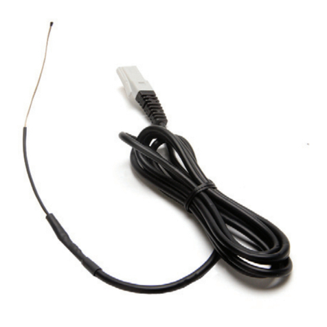
lType-K Thermocouple Wire
lMicro USBCable
Compatible Software and Interfaces
See www.vernier.com/manuals/gdx-tc for a list of software compatible with Go
Direct Thermocouple.
Getting Started
Please see the following link for platform-specific connection information:
www.vernier.com/start/gdx-tc
Bluetooth Connection USB Connection
1. Ensure the thermocouple wire is
securely connected to the
thermocouple amplifier box with
the + and – symbols aligned.
2. Install Vernier Graphical
Analysis™ on your computer,
Chromebook™, or mobile device. If
using LabQuest®, make sure
LabQuest App is up to date. See
www.vernier.com/ga4 for Graphical
Analysis availability or
www.vernier.com/downloads to
1. Ensure the thermocouple wire is
securely connected to the
thermocouple amplifier box with
the + and – symbols aligned.
2. If using a computer or
Chromebook, install Graphical
Analysis. If using LabQuest, make
sure LabQuest App is up to date.
See www.vernier.com/ga4 for
Graphical Analysis availability or
www.vernier.com/downloads to
update LabQuest App.
2
Note: The K-type channel is the default channel for this sensor. All channels are
mutually exclusive. In order to collect data from the other temperature channels,
you must also attach the applicable corresponding thermocouple wire to the
amplifier box.
Calibrating the Sensor
You should not have to perform a new calibration when using Go Direct
Thermocouple in the classroom. The sensor is custom calibrated before it is
shipped. If you wish to calibrate the sensor, you can conduct a one-point
calibration in the software. This calibration will be stored automatically to the
sensor.
Specifications
Temperature range –200°C to 1400°C
Typical accuracy ±2.2°C or 0.75% of reading, whichever is
greater
Compatible thermocouple
wires
K-type, J-type, and T-type
Wireless Specification Bluetooth 4.2
Battery 300 mA Li-Poly
Care and Maintenance
Battery Information
Go Direct Thermocouple contains a small lithium-ion battery. The system is
designed to consume very little power and not put heavy demands on the
battery. Although the battery is warranted for one year, the expected battery life
should be several years. Replacement batteries are available from Vernier
(ordercode:GDX-BAT-300).
Storage and Maintenance
To store Go Direct Thermocouple for extended periods of time, put the device
in sleep mode by holding the button down for at least three seconds. The red
LED will stop flashing to show that the unit is in sleep mode. Over several
months, the battery will discharge but will not be damaged. After such storage,
charge the device for a few hours, and the unit will be ready for use.
Exposing the amplifier box to temperatures below –15°C or over 45°C will
damage it. Additionally, temperatures over 35°C (95°F) will reduce the battery's
lifespan. If possible, store the device in an area that is not exposed to
temperature extremes.
Water Resistance
Important: Go Direct Thermocouple is neither waterproof, nor is it water
resistant and should never be immersed in water.
Powering the Sensor
Turning on the sensor Press button once. Red LED indicator flashes
when unit is on.
Putting the sensor in sleep
mode
Press and hold button for more than three
seconds to put into sleep mode. Red LED
indicator stops flashing when sleeping.
Connecting the Sensor
See the following link for up-to-date connection information:
www.vernier.com/start/gdx-tc
Connecting via Bluetooth Wireless Technology
Ready to
connect
Red LED flashes when sensor is powered and ready to
connect.
Connected Green LED flashes when sensor is connected via Bluetooth
wireless technology.
Connecting via USB
Connected via USB, data collection
software is not running
Red LED flashes when sensor is
powered and ready to connect.
Connected via USB, data collection
software is running
Green LED is solid when connected to
the software via USB.
Identifying the Sensor
Use the Identify feature to flash the LED on the sensor that is connected via
Bluetooth wireless technology. In Graphical Analysis, Identify is accessed from
Sensor Information. In LabQuest App, Identify is accessed by tapping the sensor
meter, then tapping Go Direct.
Using the Product
Connect the sensor following the steps in the Getting Started section of this user
manual.
The thermocouple wire is insulated by a high-temperature glass that has a lower
maximum temperature (704°C, 1300°F) than the wire itself (1400°C, 2552°F).
Therefore, in use, place only the tip of the wire in the heat source and keep the
insulation out of direct contact with the heat source.
Channels
Go Direct Thermocouple has three sensor channels:
lK-type (default)
lJ-type
lT-type
3
Warranty
Warranty information for this product can be found on the Support tab at
www.vernier.com/gdx-tc
General warranty information can be found at www.vernier.com/warranty
Disposal
When disposing of this electronic product, do not treat it as household waste. Its
disposal is subject to regulations that vary by country and region. This item
should be given to an applicable collection point for the recycling of electrical
and electronic equipment. By ensuring that this product is disposed of correctly,
you help prevent potential negative consequences on human health or on the
environment. The recycling of materials will help to conserve natural resources.
For more detailed information about recycling this product, contact your local
city office or your disposal service.
Battery recycling information is available at www.call2recycle.org
Do not puncture or expose the battery to excessive heat or flame.
The symbol, shown here, indicates that this product must not be disposed of
in a standard waste container.
Federal Communication Commission Interference Statement
This equipment has been tested and found to comply with the limits for a Class B digital device, pursuant to Part 15 of the FCC rules.
These limits are designed to provide reasonable protection against harmful interference in a residential installation. This equipment
generates, uses and can radiate radio frequency energy and, if not installed and used in accordance with the instructions, may cause
harmful interference to radio communications. However, there is no guarantee that interference will not occur in a particular installation. If
this equipment does cause harmful interference to radio or television reception, which can be determined by turning the equipment off and
on, the user is encouraged to try to correct the interference by one or more of the following measures:
Reorient or relocate the receiving antenna.
Increase the separation between the equipment and receiver.
Connect the equipment into an outlet on a circuit different from that to which the receiver is connected.
Consult the dealer or an experienced radio/TV technician for help.
FCC Caution
This device complies with Part 15 of the FCC Rules. Operation is subject to the following two conditions:
(1) this device may not cause harmful interference and
(2) this device must accept any interference received, including interference that may cause undesired operation
RF Exposure Warning
The equipment complies with RF exposure limits set forth for an uncontrolled environment. The antenna(s) used for this transmitter must
not be co-located or operating in conjunction with any other antenna or transmitter. You are cautioned that changes or modifications not
expressly approved by the party responsible for compliance could void your authority to operate the equipment.
IC Statement
This device complies with Industry Canada license-exempt RSS standard(s). Operation is subject to the following two conditions:
(1) this device may not cause interference, and
(2) this device must accept any interference, including interference that may cause undesired operation of the device.
Industry Canada - Class B This digital apparatus does not exceed the Class B limits for radio noise emissions from digital apparatus
as set out in the interference-causing equipment standard entitled “Digital Apparatus,” ICES-003 of Industry Canada. Operation is subject
to the following two conditions: (1) this device may not cause interference, and
(2) this device must accept any interference, including interference that may cause undesired operation of the device.
To reduce potential radio interference to other users, the antenna type and its gain should be so chosen that the equivalent isotropically
radiated power (e.i.r.p.) is not more than that permitted for successful communication.
RF exposure warning: The equipment complies with RF exposure limits set forth for an uncontrolled environment. The antenna(s) used
for this transmitter must not be co-located or operating in conjunction with any other antenna or transmitter.
If any liquid gets into the device, immediately power the unit down (press and
hold the power button for more than three seconds). Disconnect the sensor and
charging cable, and remove the battery. Allow the device to dry thoroughly
before attempting to use the device again. Do not attempt to dry using an
external heat source.
Note: Damage due to liquids is not covered under warranty.
How the Sensor Works
Thermocouples make use of a property that occurs when two wires composed of
dissimilar metals are joined at both ends. When one of the joined ends is heated,
a continuous current is created and flows in a thermoelectric circuit. The small
open-circuit voltage of this circuit (known as the Seebeck voltage) is a function
of the junction temperature and the composition of the two metals. (Go Direct
Thermocouple uses a K-type thermocouple wire with chromel and alumel.) By
measuring the voltage, the temperature at the joined end can be calculated.
Measuring the Seebeck voltage requires connecting a voltmeter’s leads to the
thermocouple wires. This new junction creates an additional thermocouple. In
order to compensate for this new thermocouple, we use a method called
cold-junction compensation. This method requires knowing the temperature at
the new junction. Traditionally, these junctions were held at 0°C in an ice bath.
Go Direct Thermocouple performs a direct measurement of the temperature of
the reference junction with an integrated-circuit amplifier.
Troubleshooting
The thermocouple wire is installed properly and ready to use if the LED next to
the check symbol turns green. If it turns red, your connection is not secure or
your wire may be damaged.
For troubleshooting and FAQs, see www.vernier.com/til/7738
Repair Information
If you have followed the troubleshooting steps and are still having trouble with
your Go Direct Thermocouple, contact Vernier Technical Support at
support@vernier.com or call 888-837-6437. Support specialists will work with
you to determine if the unit needs to be sent in for repair. At that time, a Return
Merchandise Authorization (RMA) number will be issued and instructions will
be communicated on how to return the unit for repair.
Accessories/Replacements
Item Order Code
Micro USBCable CB-USB-MICRO
Type-KThermocouple Wire KWIRE-TCA
Go Direct 300 mAh Replacement Battery GDX-BAT-300
4
Le présent appareil est conforme aux CNR d’Industrie Canada applicables aux appareils radio exempts de licence. L’exploitation est
autorisée aux deux conditions suivantes :
(1) l’appareil ne doit pas produire de brouillage, et
(2) l’appareil doit accepter tout interférence radioélectrique, même si cela résulte à un brouillage susceptible d’en compromettre le
fonctionnement.
Cet appareil numérique respecte les limites de bruits radioélectriques applicables aux appareils numériques de Classe B prescrites dans
la norme sur le matériel interférant-brouilleur: “Appareils Numériques,” NMB-003 édictée par industrie Canada. L’utilisation est soumise
aux deux conditions suivantes:
(1) cet appareil ne peut causer d’interférences, et
(2) cet appareil doit accepter toutes interférences, y comprises celles susceptibles de provoquer un disfonctionnement du dispositif.
Afin de réduire les interférences radio potentielles pour les autres utilisateurs, le type d’antenne et son gain doivent être choisie de telle
façon que l’équivalent de puissance isotrope émis (e.i.r.p) n’est pas plus grand que celui permis pour une communication établie.
Avertissement d’exposition RF: L’équipement est conforme aux limites d’exposition aux RF établies pour un environnement non
supervisé. L’antenne (s) utilisée pour ce transmetteur ne doit pas être jumelés ou fonctionner en conjonction avec toute autre antenne ou
transmetteur.
Note: This product is a sensitive measurement device. For best results, use the cables that were provided. Keep the device away from
electromagnetic noise sources, such as microwaves, monitors, electric motors, and appliances.
Vernier Software & Technology
13979 SW Millikan Way • Beaverton, OR 97005-2886
Toll Free (888) 837-6437 • (503) 277-2299 • Fax (503) 277-2440
info@vernier.com • www.vernier.com
3/29/2021
Go Direct, Vernier Graphical Analysis, LabQuest, and other marks shown are our trademarks or registered
trademarks in the United States. All other marks not owned by us that appear herein are the property of their
respective owners, who may or may not be affiliated with, connected to, or sponsored by us.
The Bluetooth®word mark and logos are registered trademarks owned by the Bluetooth SIG, Inc. and any use of
such marks by Vernier Software & Technology is under license. Other trademarks and trade names are those of
their respective owners.

This manual suits for next models

1

Other Vernier Accessories manuals

Vernier Go Direct GDX-WRT User manual

Vernier

Vernier Go Direct GDX-WRT User manual

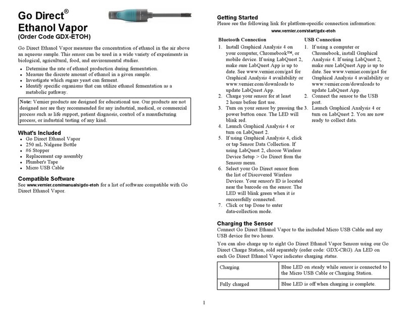
Vernier Go Direct GDX-ETOH User manual

Vernier

Vernier Go Direct GDX-ETOH User manual

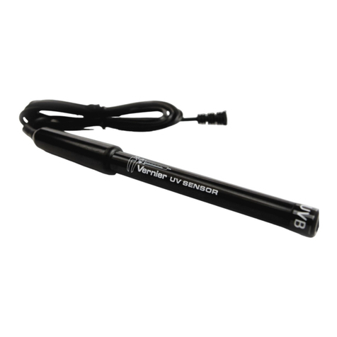
Vernier UVB-BTA User manual

Vernier

Vernier UVB-BTA User manual

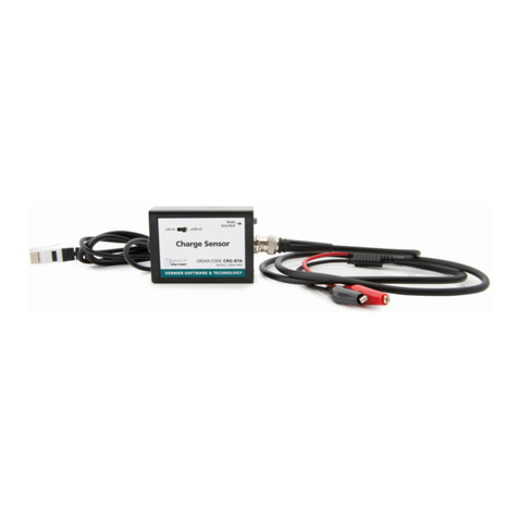
Vernier O2-BTA User manual

Vernier

Vernier O2-BTA User manual

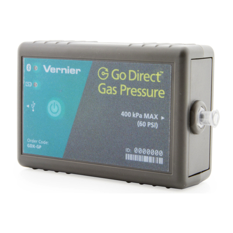
Vernier Go Direct Gas Pressure User manual

Vernier

Vernier Go Direct Gas Pressure User manual

Vernier MG-BTA User manual

Vernier

Vernier MG-BTA User manual

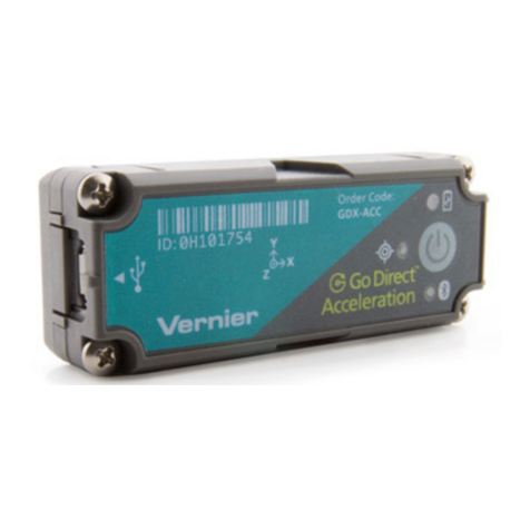
Vernier Go Direct Acceleration User manual

Vernier

Vernier Go Direct Acceleration User manual

Vernier Go Direct Surface Temperature User manual

Vernier

Vernier Go Direct Surface Temperature User manual

Vernier TRB-BTA User manual

Vernier

Vernier TRB-BTA User manual

Vernier Go Direct GDX-3MG User manual

Vernier

Vernier Go Direct GDX-3MG User manual

Vernier RH-BTA User manual

Vernier

Vernier RH-BTA User manual

Vernier Go Wireless GW-PH User manual

Vernier

Vernier Go Wireless GW-PH User manual

Vernier FPH-BTA User manual

Vernier

Vernier FPH-BTA User manual

Vernier Go Direct GDX-CART-Y User manual

Vernier

Vernier Go Direct GDX-CART-Y User manual

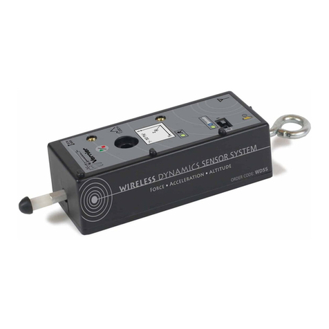
Vernier WDSS User manual

Vernier

Vernier WDSS User manual

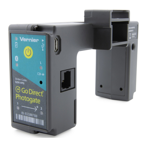
Vernier Go Direct Photogate User manual

Vernier

Vernier Go Direct Photogate User manual

Vernier Go Direct GDX-DC User manual

Vernier

Vernier Go Direct GDX-DC User manual

Vernier Go Direct Light and Color GDX-LC User manual

Vernier

Vernier Go Direct Light and Color GDX-LC User manual

Vernier Go Direct Sound User manual

Vernier

Vernier Go Direct Sound User manual

Vernier STS-BTA User manual

Vernier

Vernier STS-BTA User manual

Vernier Go Direct pH User manual

Vernier

Vernier Go Direct pH User manual

Vernier CO2-BTA User manual

Vernier

Vernier CO2-BTA User manual

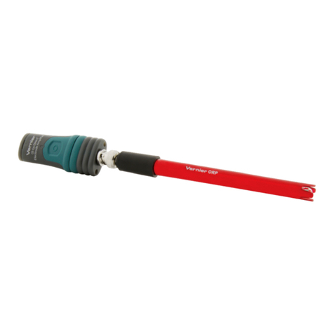
Vernier Go Direct GDX-ORP User manual

Vernier

Vernier Go Direct GDX-ORP User manual

Vernier Go Direct TrisCompatible Flat pH User manual

Vernier

Vernier Go Direct TrisCompatible Flat pH User manual

Popular Accessories manuals by other brands

BALLHOG Ascent Series manual

BALLHOG

BALLHOG Ascent Series manual

Zamel LARGO GNS-208 quick start guide

Zamel

Zamel LARGO GNS-208 quick start guide

Fiamma F80L Installation and usage instructions

Fiamma

Fiamma F80L Installation and usage instructions

Porter 4414061 ASSEMBLY, MAINTENANCE & USAGE MANUAL

Porter

Porter 4414061 ASSEMBLY, MAINTENANCE & USAGE MANUAL

Pro-Elec RCD-1UK quick start guide

Pro-Elec

Pro-Elec RCD-1UK quick start guide

Gogen ME SENZOR 32 user manual

Gogen

Gogen ME SENZOR 32 user manual

Taurus COMFORT THERM CPH-20 manual

Taurus

Taurus COMFORT THERM CPH-20 manual

polarmond All-in-one sleep shell instruction manual

polarmond

polarmond All-in-one sleep shell instruction manual

Emos TGE-5 manual

Emos

Emos TGE-5 manual

Vissani VXBC310BSSL Use and care guide

Vissani

Vissani VXBC310BSSL Use and care guide

Omron Photomicrosensor (Transmissive) EE-SX1107 specification

Omron

Omron Photomicrosensor (Transmissive) EE-SX1107 specification

Buhler EGK 10 Installation and operation instructions

Buhler

Buhler EGK 10 Installation and operation instructions

TZS First AUSTRIA FA-5170-2 instruction manual

TZS First AUSTRIA

TZS First AUSTRIA FA-5170-2 instruction manual

Azbil HP7 Series user manual

Azbil

Azbil HP7 Series user manual

Argo BabyJoy manual

Argo

Argo BabyJoy manual

Solidux Primasol manual

Solidux

Solidux Primasol manual

Flymaster B1 user manual

Flymaster

Flymaster B1 user manual

Hunter Wireless Rain-Clik Product information

Hunter

Hunter Wireless Rain-Clik Product information

manuals.online logo
manuals.online logoBrands
  • About & Mission
  • Contact us
  • Privacy Policy
  • Terms and Conditions

Copyright 2025 Manuals.Online. All Rights Reserved.