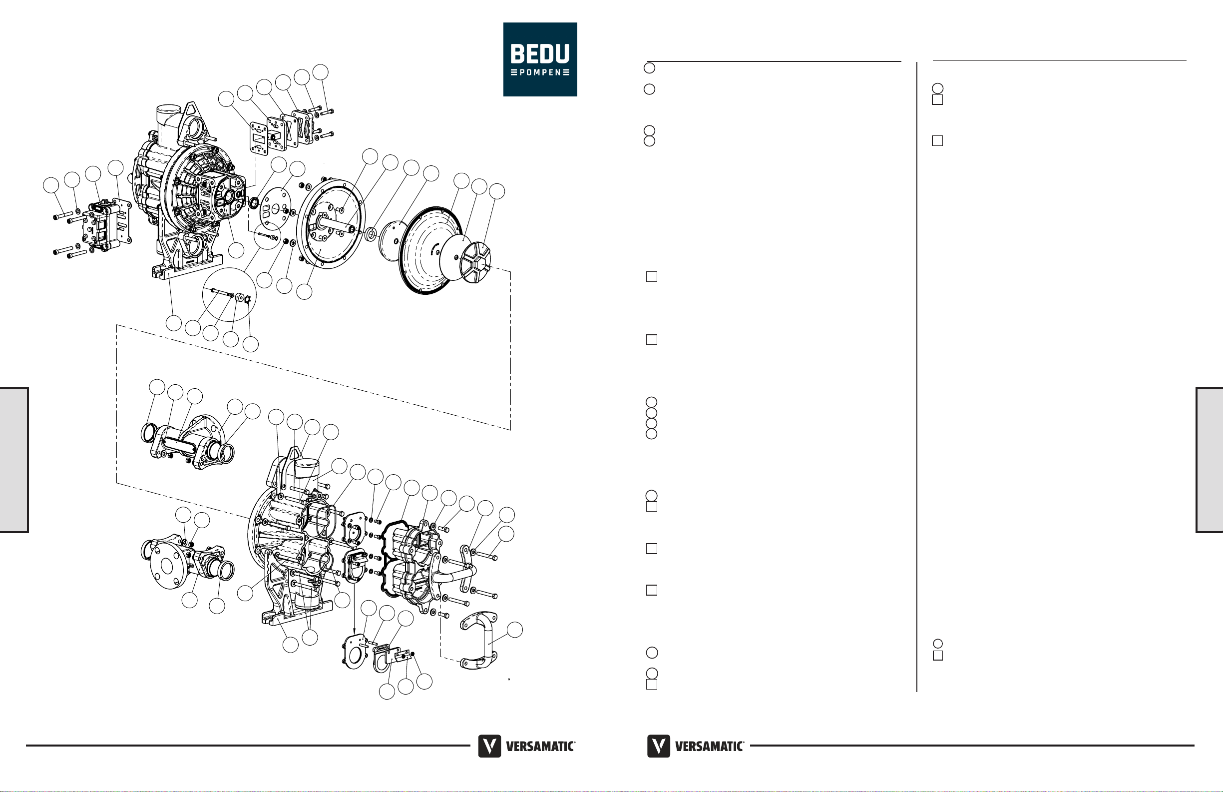
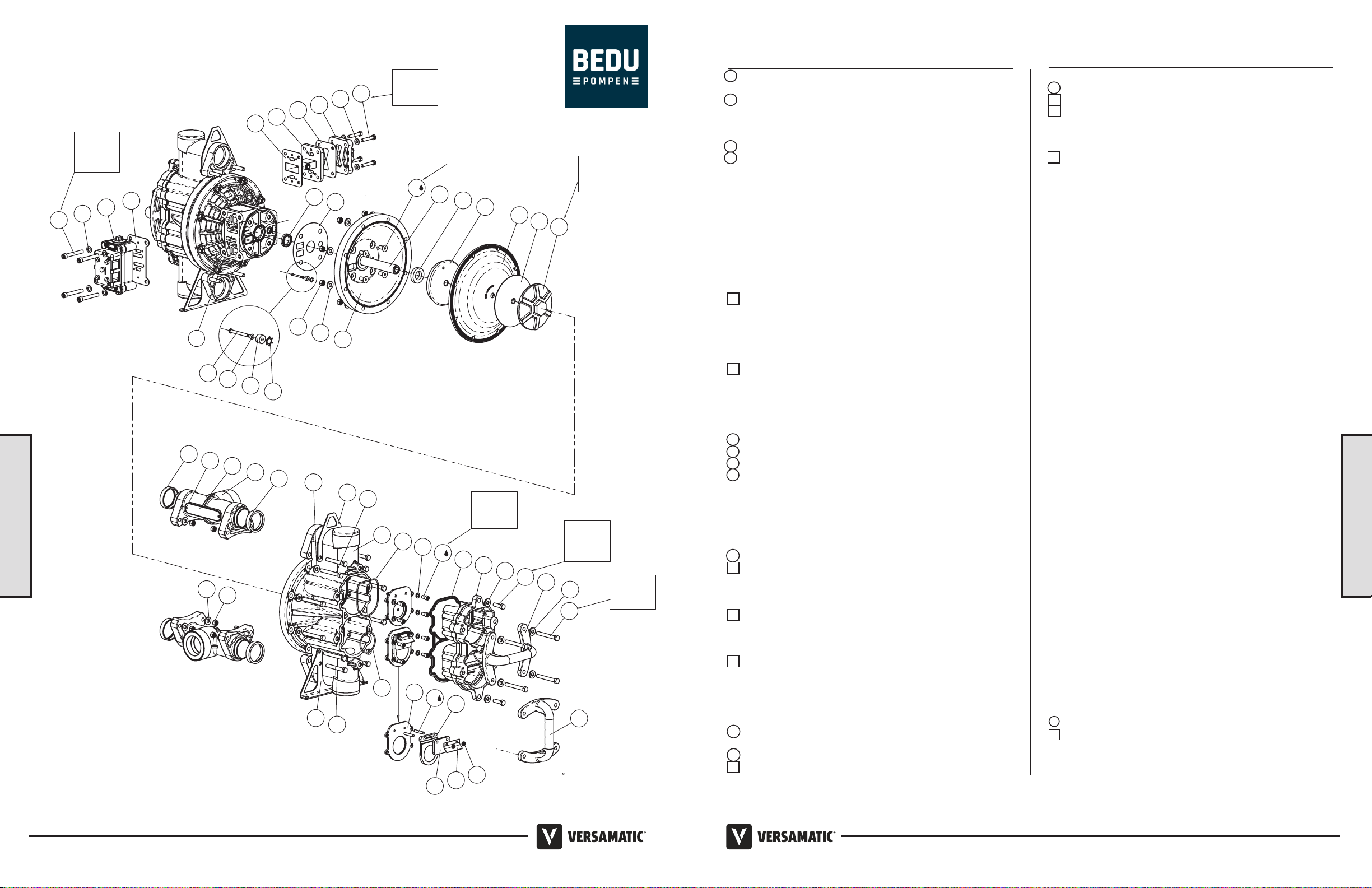
Composite Repair Parts Drawing
19
35
5
18
25 50
13
50 10
43
16
47
44
31
34
6
26 39
11
48
23
2
12
4
13
50
21
1
49
15
24
42
9
40
14
50 28
50
28
17
39 41 27
8
22
OPTIONAL 90
ROTATION
25
33
36
3
30 738
45 46 20
32 37 29
Torque:
120 in-lbs.
(13 N-m)
Torque:
120 in-lbs.
(13 N-m)
Torque:
150 in-lbs.
(16.9 N-m) Torque:
480 in-lbs.
(54 N-m)
Torque:
150 in-lbs.
(16.9 N-m)
Torque:
220 in-lbs.
(24 N-m)
Torque:
220 in-lbs.
(24 N-m)
Item #14: use 242 Loctite or equivalent anaerobic adhesive during installation
Item #16: use 242 Loctite or equivalent anaerobic adhesive during installation
Item #46: if studs are replaced use 277 Loctite or equivalent anaerobic adhesive during installation
Item Part Number Description Qty
1 ** 031.140.000 Air Valve Assembly (Integral Muer) 1
031.141.000 Air Valve Assembly (No Muer) 1
2 095.110.558 Pilot Valve Assembly 1
3 114.024.551 Intermediate Assembly 1
4 115.174.115 Bracket, Foot 2
5 115.177.115 Bracket, Hanging 2
6 132.035.357 Bumper 2
7 135.034.506 Bushing, Plunger 2
8 165.118.551 Cap, Air Inlet 1
9 165.148.551 Cap, Clean Out 2
10 170.018.115 Capscrew, Hex-Hd, 3/8-16 x 1 1/4 4
11 170.069.115 Capscrew, Hex-Hd, 5/16-18 x 1 3/4 4
12 170.129.115 Capscew, Hex-Hd, 3/8-16 x 2 3/4 8
13 170.130.115 Capscrew, Hex-Hd, 3/8-16 x 3 24
14 171.015.115 Capscrew, Flat-Hd, 3/8-16 x 7/8 8
15 171.053.115 Capscrew, Socket-Hd, 3/8-16 x 2 1/2 4
16 171.102.110 CAPSCREW, Socket Hd, 5/16 -18 x .63 16
17 196.217.551 Chamber, Inner 2
18 196.218.552 Chamber, Outer 2
19 286.007.360 Diaphragm, Buna-N 2
286.007.363 Diaphragm, Fluorocarbon FKM 2
286.007.364 Diaphragm, EPDM 2
286.007.365 Diaphragm, Neoprene 2
286.007.354 Diaphragm, Santoprene 2
286.007.356 Diaphragm, Hytrel 2
20 338.005.360 Flap Valve, Buna-N 4
338.005.363 Flap Valve, Fluorocarbon FKM 4
338.005.364 Flap Valve, EPDM 4
338.005.365 Flap Valve, Neoprene 4
338.010.356 Flap Valve, Hytrel 4
338.010.357 Flap Valve, Urethane 4
21 360.093.360 Gasket, Main Air Valve 1
22 360.103.360 Gasket, Pilot Valve 1
23 360.104.360 Gasket, Air Inlet Cap 1
24 360.105.360 Gasket, Inner Chamber 2
25 405.013.551 Handle 2
26 518.222.552 Manifold 2
518.222.552 E Manifold 2
27 535.099.000 Plate, Name 2
28 545.005.115 Nut, Hex 24
29 547.002.110 Nut, Stop 8
30 560.001.360 O-ring 2
31 560.213.360 O-ring, Buna-N 2
560.213.363 O-ring, Fluorocarbon FKM 2
560.213.364 O-ring, EPDM 2
560.213.365 O-ring, Neoprene 2
32 570.001.360 Hinge Pad, Buna-N 4
570.001.363 Hinge Pad, Fluorocarbon FKM 4
570.001.364 Hinge Pad, EPDM 4
570.001.365 Hinge Pad, Neoprene 4
33 570.009.360 Pad, Wear, Buna-N 2
570.009.363 Pad, Wear, Fluorocarbon FKM 2
570.009.364 Pad, Wear, EPDM 2
570.009.365 Pad, Wear, Neoprene 2
34 612.195.157 Plate, Inner Diaphragm 2
35 612.225.552 Plate, Outer Diaphragm (with stud) 2
36 620.007.114 Pin, Plunger 2
37 670.005.110 Retainer, Flap Valve 4
38 675.042.115 Ring, Retaining 2
39 675.073.360 Ring Sealing, Buna-N 4
675.073.363 Ring Sealing, Fluorocarbon FKM 4
675.073.364 Ring Sealing, EPDM 4
675.073.365 Ring Sealing, Neoprene 4
Composite Repair Parts List
LEGEND:
= Items contained within Air End Kits
= Items contianed within Wet End Kits
Note: Kits contain components specic to the material codes.
**Air End Kit does not include entire air valves assembly. It includes
replacement sleeve and spool set, plus o-rings.
Item Part Number Description Qty
40 685.059.120 Rod, Diaphragm 1
41 710.021.115 Screw, Pan Head 4
42 720.004.360 Seal, U-cup 2
43 720.076.360 Seal, Clean Out Cap, Buna-N 2
720.076.363
Seal, Clean Out Cap, Fluorocarbon FKM
2
720.076.364 Seal, Clean Out Cap, EPDM 2
720.076.365 Seal, Clean Out Cap, Neoprene 2
44 720.077.360 Seal, Seat, Buna-N 2
720.077.363 Seal, Seat, Fluorocarbon FKM 2
720.077.364 Seal, Seat, EPDM 2
720.077.365 Seal, Seat, Neoprene 2
45 722.129.110 Seat, Check Valve (includes studs) 4
46 807.018.110 Stud 8
47 900.004.110 Washer, Lock 5/16 16
48 901.038.115 Washer, Flat 5/16 4
49 901.048.115 Washer, Flat 3/8 4
50 901.052.115 Washer, Flat 3/8 48
Model E2 Bolted Plastic Flap • 1312 • Model E2 Bolted Plastic Flap